Table of Contents
Advertisement
Advertisement
Table of Contents

Related Manuals for IBM Brocade FCoE


Summary of Contents for IBM Brocade FCoE
- Page 1 Brocade FCoE Switch Module for IBM BladeCenter Installation and User’s Guide...
- Page 3 Brocade FCoE Switch Module for IBM BladeCenter Installation and User’s Guide Brocade FCoE Switch Module for IBM BladeCenter: Installation and User Guide...
- Page 4 Note: Before using this information and the product it supports, read the general information in the IBM Warranty and Support Guide and the IBM Safety Information and the IBM Systems Environmental Notices and User Guide on the IBM Documentation CD.
-
Page 5: Table Of Contents
Safety Chapter 1. Introducing the Brocade FCoE Switch Module Components ..........1 Dynamic Ports on Demand. - Page 6 IBM Taiwan product service ........
- Page 7 Regulatory Compliance ......... . . 55 Index Brocade FCoE Switch Module for IBM BladeCenter: Installation and User Guide...
- Page 8 Brocade FCoE Switch Module for IBM BladeCenter: Installation and User Guide...
- Page 9 Vor der Installation dieses Produkts die Sicherheitshinweise lesen. Prima di installare questo prodotto, leggere le Informazioni sulla Sicurezza. Les sikkerhetsinformasjonen (Safety Information) før du installerer dette produktet. Antes de instalar este produto, leia as Informações sobre Segurança. © Copyright IBM Corp. 2010...
- Page 10 • Connect to properly wired outlets any equipment that will be attached to this product. • When possible, use one hand only to connect or disconnect signal cables. Brocade FCoE Switch Module for IBM BladeCenter: Installation and User Guide...
- Page 11 Statement 2: CAUTION: ® When replacing the lithium battery, use only IBM Part Number 33F8354 or an equivalent type battery recommended by the manufacturer. If your system has a module containing a lithium battery, replace it with only the same module type made by the same manufacturer. The battery contains lithium and can explode if not properly used, handled, or disposed of.
- Page 12 Luokan 1 Laserlaite Appareil A` Laser de Classe 1 Statement 8: CAUTION: Never remove the cover on a power supply or any part that has the following label attached. Brocade FCoE Switch Module for IBM BladeCenter: Installation and User Guide...
- Page 13 Hazardous voltage, current, and energy levels are present inside any component that has this label attached. There are no serviceable parts inside these components. If you suspect a problem with one of these parts, contact a service technician. xiii...
- Page 14 Brocade FCoE Switch Module for IBM BladeCenter: Installation and User Guide...
-
Page 15: Chapter 1. Introducing The Brocade Fcoe Switch Module
Notes: 1. Throughout this document, including the references to screen contents, the Brocade FCoE Switch Module is generically referred to as the high speed switch module, HSSM, or the switch module. With respect to certain screen contents or titles, a high speed switch module might be referred to as a switch module or switch, because the term switch module or switch appears on those screens. -
Page 16: Dynamic Ports On Demand
One external 10/100/1000 Mb RJ45 Ethernet copper port for debugging and field support Dynamic Ports on Demand The base version of the Brocade FCoE Switch Module ships with 16 licensed ports. Port activation is through a process called Dynamic Ports on Demand (DPOD). -
Page 17: Additional Information
(MAC) address is on a separate label on the bottom cover of the switch module. For an illustration that shows the locations of these labels, see “Major components of the switch module” on page 5. You will need this information when you register the switch module with IBM. You can register the switch module at http://www.ibm.com/support/mysupport/. -
Page 18: Inventory Checklist
Web sites. Inventory checklist Make sure that the shipping carton contains the following items: • One Brocade FCoE Switch Module for IBM BladeCenter (base model has two 10GbE SFP+ modules) • IBM Important Notices document •... -
Page 19: Notices And Statements In This Document
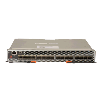
The caution and danger statements in this document are also in the multilingual Safety Information document, which is on the IBM BladeCenter Documentation CD for the BladeCenter unit. Each statement is numbered for reference to the corresponding statement in your language in the Safety Information document. - Page 20 RJ45 Ethernet port (eth1) mini-USB console port Fibre Channel ports 10GbE FCoE/CEE ports Release latches Release levers FIGURE 1 Major components Brocade FCoE Switch Module for IBM BladeCenter: Installation and User Guide...
-
Page 21: Chapter 2. Installing And Replacing A High Speed Switch Module
BladeCenter chassis. In the BCHT, these bays are in the front of the BladeCenter chassis. NOTE The Brocade FCoE Switch Module is a double-height unit and thus takes up two HSSM bays when installed. HSSM bays 7 and 8... - Page 22 Ethernet network or Fibre Channel SAN. The BladeCenter unit supports a maximum of two Brocade FCoE Switch Modules. The BladeCenter H chassis supports a maximum of 14 compatible expansion cards and the BladeCenter HT chassis supports a maximum of 12 compatible expansion cards.
-
Page 23: Installation Guidelines
When you are finished working on the blade server or BladeCenter unit, reinstall all safety shields, guards, labels, and ground wires. • For a list of supported optional devices for the BladeCenter unit and other IBM products, see http://www.ibm.com/servers/eserver/serverproven/compat/us/. System reliability guidelines... -
Page 24: Handling Static-Sensitive Devices
Cable requirements for the switch module are described in the IBM Configuration and Options Guide at http://www.ibm.com/servers/eserver/xseries/cog/. See the documentation that comes with the blade server for cable-routing information Handling static-sensitive devices Attention: Static electricity can damage the BladeCenter unit and other electronic devices. To avoid damage, keep static-sensitive devices in their static-protective packages until you are ready to install them. - Page 25 Brocade FCoE Switch Module Release levers (open position) FIGURE 4 High speed switch module insertion 1. Read the safety information that begins on page ix “Installation guidelines” on page 9. 2. Select the high-speed module bay in which to install the switch module.
-
Page 26: Removing Or Replacing A Switch Module
8852 BladeCenter unit. The appearance of your BladeCenter unit might be different; see the documentation for your BladeCenter unit for additional information. To replace a switch module, complete the following steps: Brocade FCoE Switch Module for IBM BladeCenter: Installation and User Guide... - Page 27 Brocade FCoE Switch Module Release levers (open position) FIGURE 5 High speed switch module removal 1. Read the safety information that begins on page ix, and “Installation guidelines” on page 9. 2. Disconnect any cables from the switch module that you are removing. Removing these cables (especially an Ethernet cable) disrupts the network connection from the external Ethernet port to any connected external Ethernet devices.
- Page 28 Brocade FCoE Switch Module for IBM BladeCenter: Installation and User Guide...
-
Page 29: Chapter 3. Installing And Removing An Sfp+ Module
Some laser products contain an embedded Class 3A or Class 3B laser diode. Note the following: Laser radiation when open. Do not stare into the beam, do not view directly with optical instruments, and avoid direct exposure to the beam. © Copyright IBM Corp. 2010... -
Page 30: Installing An Sfp+ Module
To avoid damage to the cable or the SFP+ module, make sure that you do not connect the fiber optic cable before you install the SFP+ module. Insert the SFP+ module into the SFP+ module port until it clicks into place. Brocade FCoE Switch Module for IBM BladeCenter: Installation and User Guide... -
Page 31: Removing An Sfp+ Module
FC ports Protective cap FCoE/CEE ports SFP+ module FIGURE 6 SFP+ installation 8. Remove the protective cap from the transceiver and connect the fiber optic cable (see “Connecting the SFP+ module cable” on page 20) and any cables that you disconnected earlier. - Page 32 5. Grasp the wire tab on the SFP+ module and pull it out of the port. 6. Replace the protective cap on the SFP+ module and the port. Place the SFP+ module into a static-protective package. Brocade FCoE Switch Module for IBM BladeCenter: Installation and User Guide...
-
Page 33: Chapter 4. Cabling The Switch Module And The Sfp+ Module
The USB console cable supplied with the Brocade FCoE Switch Module has a mini-USB connector for the switch module connection and a DB9 male connector to connect to your console device. -
Page 34: Connecting The Sfp+ Module Cable
1. Remove the protective caps from the end of the fiber optic cable. Fiber optic cable Protective cap FIGURE 9 Fiber optic cable cap 2. Gently slide the fiber optic cable into the SFP+ module until it clicks into place. Brocade FCoE Switch Module for IBM BladeCenter: Installation and User Guide... -
Page 35: Disconnecting The Sfp+ Module Cable
FC ports Fiber optic cable CEE ports SFP+ module FIGURE 10 Fiber optic cable insertion 3. Check the LEDs on the switch module. When the switch module is operating correctly, the green link LED is lit. For information about the status of the switch module LEDs, see “Chapter 5. -
Page 36: Disconnecting The Rj-45 Cable
FIGURE 11 RJ-45 cable connection Disconnecting the RJ-45 cable To disconnect the RJ-45 connector, squeeze the release tab and gently pull the cable connector out of the switch module connector. Brocade FCoE Switch Module for IBM BladeCenter: Installation and User Guide... -
Page 37: Chapter 5. Information Panels, Leds, And External Ports
For further details about LEDs, see “Information LEDs” on page 24. • Eight FC SFP+ port connectors to attach SFP+ modules. They are numbered 23-30 right to left. • Eight FCoE/CEE SFP+ port connectors to attach SFP+ modules. They are numbered 15-22 right to left © Copyright IBM Corp. 2010... -
Page 38: Information Leds
For more information, see the documentation for the BladeCenter unit. Switch module status LEDs The following table provides descriptions of the switch module status LEDs on the front panel of the switch module. Brocade FCoE Switch Module for IBM BladeCenter: Installation and User Guide... -
Page 39: Port Status Leds
TABLE 2 Switch module status LEDs Status LED Description • Steady amber. Status/fault (!) LED (amber) There has been a POST failure or critical alert. Note: When this LED is lit, the system-error LED on the BladeCenter unit is also lit. •... -
Page 40: Post-Operation Led Indications
POST critical failure (nonfunctional) POST noncritical failure (functioning but degraded mode) POST successful complete Extended POST start Blinking Extended POST critical failure (nonfunctional) Extended POST noncritical failure (functioning but degraded mode) Brocade FCoE Switch Module for IBM BladeCenter: Installation and User Guide... -
Page 41: Chapter 6. Configuring The Switch Module
Ethernet connector on the management module. The Internet protocol (IP) addresses and SNMP parameters of the switch modules can be automatically assigned by the IBM Director BladeCenter Deployment wizard (when available), or you must assign them through the BladeCenter Management and Configuration Program. -
Page 42: Establishing A Tcp/Ip Session Through The Management Module
IP subnet. • Only one FCoE-capable VLAN can be configured on the Brocade FCoE Switch Module. For specific details about configuring the switch module and preparing for system installation, see the documentation listed in “Related documentation” on page 3. -
Page 43: Enabling Management Through External Ports
4. In the IP address field in the New Static IP Configuration area, type the new TCP/IP address of the switch module; then, click Save. NOTE The management module does not check for invalid IP addresses. 5. Click Advanced Configuration. You can now start a Web session or a Telnet session. The Web interface and the Telnet program provide different ways to access the same internal-switching software and configure it. -
Page 44: Configuring The Switch Module Through The Telnet Interface
Important: The apply command changes the currently active configuration. If you want your change to persist beyond the next reboot of the switch, you must enter the save command. This command stores the current switch configuration and all changes in nonvolatile memory. Brocade FCoE Switch Module for IBM BladeCenter: Installation and User Guide... -
Page 45: Configuring The Switch Module Through The Mini-Usb Interface
Configuring the switch module through the mini-USB interface The mini-USB port provides basic communication serial-data transfer through a terminal emulation program (such as Hyperterminal). Because messages from the power-on self-test (POST) and all initialization information are transmitted through the serial port, you can use the serial port to log in to the switch module and access and configure the internal switching software. -
Page 46: Initial Configuration
CEE command shell. Use the following steps to configure the CEE ports. 1. Login to the switch. 2. From the command prompt type cmsh and press Enter. 3. Type enable and press Enter. Brocade FCoE Switch Module for IBM BladeCenter: Installation and User Guide... -
Page 47: Backing Up The Configuration
4. Type conf t and press Enter. 5. Type int int (press tab to complete the second int) 0/x where x is the internal port you wish to change and press Enter. 6. Once in the particular interface type fcoeport and press Enter. Type no shut and press Enter. -
Page 48: Resetting The Brocade Fcoe Switch Module To Factory Defaults
2. Select I/O Module Tasks > Configuration. 3. Select either bay 7 or bay 9 depending on where the switch module is installed. 4. Select Advanced Configuration. 5. Click Restore Defaults. Brocade FCoE Switch Module for IBM BladeCenter: Installation and User Guide... -
Page 49: Chapter 7. Understanding Access Gateway
IDs and ports you simplify configuration and management in a large fabric. NOTE The Brocade FCoE Switch Module cannot be used as a core AG, only as an edge AG. However, there is no limit as to how many Brocade FCoE Switch Modules can be connected to a core AG. -
Page 50: Disabling And Enabling Access Gateway Mode
5. Enter ag –modeEnable to enable AG mode. 6. The switch reboots at this point so you must log back in to the switch. Enter the ag modeShow command to verify that AG mode is enabled. Brocade FCoE Switch Module for IBM BladeCenter: Installation and User Guide... -
Page 51: Disabling Access Gateway Mode
If an N_Port becomes unreliable, its currently active online F_Ports DO NOT failover to another N_Port. They remain on the unreliable N_Port. • The Brocade FCoE Switch Module can support only one FCoE VLAN in AG mode. • QoS is NOT disabled on the N_Ports. - Page 52 Brocade FCoE Switch Module for IBM BladeCenter: Installation and User Guide...
-
Page 53: Chapter 8. Updating The Firmware
If firmware and documentation updates are available, complete the following steps: NOTE Changes are made periodically to the IBM Web site. The procedure for locating firmware and documentation might change from what is described in this document. 1. Go to http://www.ibm.com/systems/support/. -
Page 54: Downloading The Firmware
Downloading the firmware Once you have found the correct firmware you want to download to the Brocade FCoE Switch Module, you can use either the CLI or Web Tools to do the download. NOTE The firmware download for the Brocade FCoE Switch Module is not non-disruptive. Be sure that no traffic is flowing through the switch during the download process. -
Page 55: Chapter 9. Parts
IBM installs a Tier 1 CRU at your request, you will be charged for the installation. • Tier 2 customer replaceable unit (CRU): You may install a Tier 2 CRU yourself or request IBM to install it, at no additional charge, under the type of warranty service that is designated for your server. - Page 56 Brocade FCoE Switch Module for IBM BladeCenter: Installation and User Guide...
-
Page 57: Chapter 10. Solving Problems
When critical errors occur, the switch module does not operate. To view POST results, complete the following steps: 1. Log on to the management module as described in the IBM BladeCenter Advanced Management Module Command-Line Interface Reference Guide. If necessary, obtain the IP address of the management module from your system administrator. - Page 58 00 - 7F Base internal functions Critical 80 - 9F Internal interface failures Noncritical A0 - AF External interface errors Noncritical B0 - FE Reserved Noncritical Switch module “good” indicator Operation Brocade FCoE Switch Module for IBM BladeCenter: Installation and User Guide...
-
Page 59: Appendix A. Getting Help And Technical Assistance
If you need help, service, or technical assistance or just want more information about IBM products, you will find a wide variety of sources available from IBM to assist you. This section contains information about where to go for additional information about IBM and IBM products, what to do if you experience a problem with your system, and whom to call for service, if it is necessary. -
Page 60: Getting Help And Information From The World Wide Web
IBM to provide warranty service, go to http://www.ibm.com/partnerworld/ and click Find a Business Partner on the right side of the page. For IBM support telephone numbers, see http://www.ibm.com/planetwide/. In the U.S. and Canada, call 1-800-IBM-SERV (1-800-426-7378). In the U.S. and Canada, hardware service and support is available 24 hours a day, 7 days a week. -
Page 61: Appendix B. Notices
Web sites. The materials at those Web sites are not part of the materials for this IBM product, and use of those Web sites is at your own risk. IBM may use or distribute any of the information you supply in any way it believes appropriate without incurring any obligation to you. -
Page 62: Important Notes
® a particular purpose. These products are offered and warranted solely by third parties. IBM makes no representations or warranties with respect to non-IBM products. Support (if any) for the non-IBM products is provided by the third party, not IBM. -
Page 63: Electronic Emission Notices
Properly shielded and grounded cables and connectors must be used in order to meet FCC emission limits. IBM is not responsible for any radio or television interference caused by using other than recommended cables and connectors or by unauthorized changes or modifications to this equipment. -
Page 64: United Kingdom Telecommunications Safety Requirement
EU-Mitgliedsstaaten und hält die Grenzwerte der EN 55022 Klasse A ein. Um dieses sicherzustellen, sind die Geräte wie in den Handbüchern beschrieben zu installieren und zu betreiben. Des Weiteren dürfen auch nur von der IBM empfohlene Kabel angeschlossen werden. IBM übernimmt keine Verantwortung für die Einhaltung der Schutzanforderungen, wenn das Produkt ohne Zustimmung der IBM verändert bzw. -
Page 65: Japanese Vcci Class A Statement
New Orchard Rd. Armonk, NY, 10504 914-499-1900 De verantwortliche Ansprechpartner des Herstellers in der EU ist: IBM Deutschland IBM Technical Regulations, Department 456 IBM-Allee 1, 71137 Ehningen, Germany Telephone: +49 7032 15-2937 E-mail: tjahn@de.ibm.com Generelle Informationen: Das Gerät erfüllt die Schutzanforderungen nach EN 55024 und EN 55022 Klasse A. -
Page 66: Russia Electromagnetic Interference (Emi) Class A Statement
Russia Electromagnetic Interference (EMI) Class A statement People's Republic of China Class A warning statement Taiwanese Class A warning statement Brocade FCoE Switch Module for IBM BladeCenter: Installation and User Guide... -
Page 67: Appendix C. Product Specifications
Appendix C. Product Specifications Switch components The Brocade FCoE Switch Module switch includes the following components: • Up to 14 internal ports as licensed • Sixteen external ports; eight CEE, eight FC • Two internal full duplex 100 Mbps Ethernet links for connecting to the two BladeCenter Management Modules •... -
Page 68: Environmental Requirements
0.5G, 2-200 Hz, 15 minutes; 1.04 GRMS Random for 15 minutes CNA support You can obtain up-to-date information about compatible CNA adapters and other IBM products at http://www.ibm.com/systems/support/. Fibre Channel Standards Compliance The switch module meets or exceeds the Fibre Channel standards compliance, performance, and... -
Page 69: Regulatory Compliance
X3.269:1996) Regulatory Compliance The high speed switch module has been approved for use only in the IBM BladeCenter H or BladeCenter HT product as a component by TUV. CAUTION: RISK OF EXPLOSION IF BATTERY IS REPLACED BY AN INCORRECT TYPE. DISPOSE OF USED BATTERIES ACCORDING TO THE INSTRUCTIONS. - Page 70 Brocade FCoE Switch Module for IBM BladeCenter: Installation and User Guide...
- Page 71 Canada errShow CE statement switchShow European Union EMC Directive conformance command line interface (CLI) statement commands Federal Communications Commission (FCC) ag --modeShow statement compact flash Germany Electromagnetic Compatibility Directive Industry Canada Class A emission compliance © Copyright IBM Corp. 2010...
- Page 72 FTP server management interfaces getting help memory hardware support mini-USB console port IBM documentation mini-USB interface software support World Wide Web guidelines installation reliability N_Ports static-sensitive devices noncritical errors Brocade FCoE Switch Module for IBM BladeCenter: Installation and User Guide...
- Page 73 notices switch NPIV configuring introduction N-Port ID Virtualization, see NPIV reset and restart switch components switch management via external ports switch module operating requirements front panel optical cabling installing login physical dimensions removing or replacing weight parts listing switch status LEDs password, default switchShow command license removal...
- Page 74 Brocade FCoE Switch Module for IBM BladeCenter: Installation and User Guide...
- Page 76 Part Number: 60Y1582 Printed in USA (IP) P/N: 60Y1582 *60Y1582*...