IBM BladeCenter Installation Manual
Server connectivity module
Hide thumbs
Also See for BladeCenter:
- Installation and user manual (184 pages) ,
- Installation manual (82 pages) ,
- User manual (78 pages)
Table of Contents
Advertisement
Quick Links
Advertisement
Table of Contents

Related Manuals for IBM BladeCenter


Summary of Contents for IBM BladeCenter
- Page 1 IBM BladeCenter Server Connectivity Module Installation Guide...
- Page 3 IBM BladeCenter Server Connectivity Module Installation Guide...
- Page 4 Before using this information and the product it supports, read the Warranty Information document, the general information in Appendix B, “Notices,” on page 29, and the Important Notices document that comes with the product. Read the IBM System Safety Notices and the License Agreement for Machine Code (LAMC) document on the IBM Documentation CD.
-
Page 5: Table Of Contents
Getting help and information from the World Wide Web . . 26 Software service and support . 26 Hardware service and support . . 26 IBM Taiwan product service . . 27 Appendix B. Notices . . 29 Trademarks . . 30 Important notes . - Page 6 Industry Canada Class A emission compliance statement . . 34 Avis de conformité à la réglementation d'Industrie Canada . 34 Australia and New Zealand Class A statement . 35 European Union EMC Directive conformance statement . 35 Germany Class A statement . .
-
Page 7: Safety
Avant d'installer ce produit, lisez les consignes de sécurité. Vor der Installation dieses Produkts die Sicherheitshinweise lesen. Prima di installare questo prodotto, leggere le Informazioni sulla Sicurezza. Les sikkerhetsinformasjonen (Safety Information) før du installerer dette produktet. © Copyright IBM Corp. 2012... - Page 8 IBM Safety Information book. For example, if a caution statement begins with a number 1, translations for that caution statement appear in the IBM Safety Information book under statement 1. Be sure to read all caution and danger statements in this documentation before performing the instructions.
- Page 9 Statement 1: DANGER Electrical current from power, telephone, and communication cables is hazardous. To avoid a shock hazard: v Do not connect or disconnect any cables or perform installation, maintenance, or reconfiguration of this product during an electrical storm. v Connect all power cords to a properly wired and grounded electrical outlet.
- Page 10 viii Server Connectivity Module: Installation Guide...
-
Page 11: Chapter 1. Introduction
Server Connectivity Module. For installation details, see Chapter 2, “Installing and removing components,” on page 9. For additional information, see the instructions in your BladeCenter unit documentation. The IBM BladeCenter Server Connectivity Module is also referred to throughout this document as the switch module or I/O module. - Page 12 I/O module. You will need this information when you register the I/O module with IBM. You can register the I/O module at http://www.ibm.com/support/ mysupport/. Product name...
-
Page 13: Related Documentation
SOL operation. The SOL connection provides access to the text-console command prompt on each blade server, enabling the blade servers to be managed from a remote location. The most recent versions of this Installation Guide and all other BladeCenter documentation are at http://www.ibm.com/servers/eserver/support/ bladecenter/index.html. -
Page 14: Features And Specifications
– Internal ports - Fourteen internal full-duplex Gigabit ports, one connected to each of the blade servers in the BladeCenter unit. Eight internal links in a BladeCenter-T chassis. - Two internal full-duplex 100 Mbps ports connected to the management module in slots 1 and 2. -
Page 15: Standards
Table 1. Features and specifications (continued) v Two independent internal 100 Mbps FDX links connected to each of two management modules (jumbo frame support not required on these links). v Management-module I C interface that provides VPD and register access. v Level-2 (L2) switching per current industry standards and practice. -
Page 16: Notices And Statements In This Document
Notices and statements in this document The caution and danger statements that appear in this document are also in the multilingual Safety Information document, which is on the IBM BladeCenter Documentation CD. Each statement is numbered for reference to the corresponding statement in the Safety Information document. -
Page 17: Major Components Of The I/O Module
Orange on the release latch on the I/O module identifies this device as a hot-swap component. You can install or remove this component while the BladeCenter unit is running. The following illustration shows the major components of the I/O module. - Page 18 Server Connectivity Module: Installation Guide...
-
Page 19: Chapter 2. Installing And Removing Components
Back up all important data before you make changes to disk drives. v Have a small flat-blade screwdriver available. v You do not have to turn off the BladeCenter unit to install or replace any of the hot-swap modules in the BladeCenter unit. -
Page 20: Handling Static-Sensitive Devices
If you plan to install additional I/O modules in the I/O-module bays of your BladeCenter unit, you might also have to install an I/O expansion card in the applicable blade server to support the I/O modules in these bays. For information about the types of compatible I/O expansion cards for the blade servers, contact your IBM authorized reseller. -
Page 21: Installing An I/O Module
To install an I/O module, complete the following steps. Attention: If the I/O module has a cover, make sure that the cover is installed and closed before you install the I/O module in the BladeCenter unit. 1. Read the safety information that begins on page v and “Installation guidelines”... - Page 22 5. If you have not already done so, touch the static-protective package that contains the I/O module to any unpainted metal surface of the BladeCenter unit or any unpainted metal surface on any other grounded rack component for at least 2 seconds.
-
Page 23: Removing An I/O Module
Removing an I/O module Attention: To maintain proper cooling and system reliability, each I/O-module bay in the BladeCenter unit must have either an I/O module or filler module installed. If you remove a hot-swap module, you must replace it with another module or filler module within 1 minute of removal. - Page 24 7. If you placed another I/O module in the I/O-module bay, reconnect any compatible cables that you disconnected in step 3 on page 13. If a cable that you disconnected is not compatible with the new I/O module, you will have to connect a new cable that is compatible with the new I/O module.
-
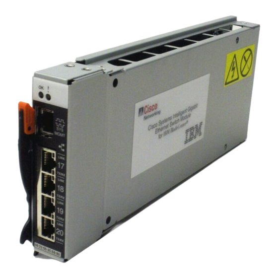
Page 25: Chapter 3. Information Panel Leds And External Ports
The following illustration shows the information panel for the I/O module. LEDs Serial port reserved SERVICE ONLY for service technician LINK TX/RX LINK LEDs TX/RX Ethernet ports LINK TX/RX LINK TX/RX LINK TX/RX LINK TX/RX © Copyright IBM Corp. 2012... -
Page 26: Leds
I/O module has failed the POST or detected an operational fault. Note: When the I/O module error LED is lit, the system-error LED on the BladeCenter unit will also be lit. Ethernet link: This green link status LED is at the top of each external 10/100/1000 Mbps port. - Page 27 Ethernet Tx/Rx: This green activity LED is at the bottom of each external 10/100/1000 Mbps port. When this LED flashes on a port, it indicates that data is being transmitted or received (that is, activity is occurring) between that port and another device on the network link.
- Page 28 Server Connectivity Module: Installation Guide...
-
Page 29: Chapter 4. Updating The Software And Configuring The Switch Module
Chapter 4. Updating the software and configuring the switch module Make sure that you are using the latest version of management module firmware for your BladeCenter unit type. See the IBM BladeCenter Management Module User's Guide for your BladeCenter unit type, located at http://publib.boulder.ibm.com/infocenter/bladectr/documentation/index.jsp for your BladeCenter unit type for additional information. - Page 30 Server Connectivity Module: Installation Guide...
-
Page 31: Chapter 5. Solving Problems
I/O module error (fault) LED and the system-error LED on the BladeCenter unit will be lit. An event is stored in the event log in the System Status panel of the management module. The specific failure is displayed on the System Status I/O Module pane of the management-module interface. - Page 32 You might have to provide this information when you call IBM. For more details, see Appendix A, “Getting help and technical assistance,” on page 25. Diagnostic indicator (in Failing functional area Failure criticality hex)
-
Page 33: Chapter 6. Parts Listing
Connectivity Module. Note: Field replaceable units (FRUs) should be serviced only by qualified field service technicians. Customer replaceable units (CRUs) can be replaced by the customer. Part CRU number CRU/FRU IBM BladeCenter Server 39Y9327 Connectivity Module © Copyright IBM Corp. 2012... - Page 34 Server Connectivity Module: Installation Guide...
-
Page 35: Appendix A. Getting Help And Technical Assistance
Appendix A. Getting help and technical assistance If you need help, service, or technical assistance or just want more information about IBM products, you will find a wide variety of sources available from IBM to assist you. This appendix contains information about where to go for... -
Page 36: Getting Help And Information From The World Wide Web
Also, some documents are available through the IBM Publications Center at http://www.ibm.com/shop/publications/order/. Getting help and information from the World Wide Web On the World Wide Web, the IBM Web site has up-to-date information about IBM BladeCenter systems, optional devices, services, and support at http://www.ibm.com/servers/eserver/support/bladecenter/index.html. -
Page 37: Ibm Taiwan Product Service
IBM Taiwan product service IBM Taiwan product service contact information: IBM Taiwan Corporation 3F, No 7, Song Ren Rd. Taipei, Taiwan Telephone: 0800-016-888 Appendix A. Getting help and technical assistance... - Page 38 Server Connectivity Module: Installation Guide...
-
Page 39: Appendix B. Notices
Web sites. The materials at those Web sites are not part of the materials for this IBM product, and use of those Web sites is at your own risk. IBM may use or distribute any of the information you supply in any way it believes appropriate without incurring any obligation to you. -
Page 40: Trademarks
Trademarks The following terms are trademarks of International Business Machines Corporation in the United States, other countries, or both: Active Memory TechConnect Active PCI IBM (logo) Tivoli Active PCI-X IntelliStation Tivoli Enterprise NetBAY Update Connector Alert on LAN Netfinity Wake on LAN... -
Page 41: Important Notes
IBM makes no representations or warranties with respect to non-IBM products. Support (if any) for the non-IBM products is provided by the third party, not IBM. Some software may differ from its retail version (if available), and may not include user manuals or all program functionality. - Page 42 IBM recomienda a los propietarios de equipos de tecnología de la información (TI) que reciclen responsablemente sus equipos cuando éstos ya no les sean útiles. IBM dispone de una serie de programas y servicios de devolución de productos en varios países, a fin de ayudar a los propietarios de equipos a reciclar sus productos de TI.
-
Page 43: Battery Return Program
In the United States, IBM has established a return process for reuse, recycling, or proper disposal of used IBM sealed lead acid, nickel cadmium, nickel metal hydride, and battery packs from IBM equipment. For information on proper disposal of these batteries, contact IBM at 1-800-426-4333. -
Page 44: Electronic Emission Notices
Properly shielded and grounded cables and connectors must be used in order to meet FCC emission limits. IBM is not responsible for any radio or television interference caused by using other than recommended cables and connectors or by unauthorized changes or modifications to this equipment. -
Page 45: Australia And New Zealand Class A Statement
IBM cannot accept responsibility for any failure to satisfy the protection requirements resulting from a nonrecommended modification of the product, including the fitting of non-IBM option cards. Attention: This is an EN 55022 Class A product. In a domestic environment this product may cause radio interference in which case the user may be required to take adequate measures. -
Page 46: Deutschland: Einhaltung Des Gesetzes Über Die Elektromagnetische Verträglichkeit Von Geräten
Zustimmung der IBM verändert bzw. wenn Erweiterungskomponenten von Fremdherstellern ohne Empfehlung der IBM gesteckt/eingebaut werden. EN 55022 Klasse A Geräte müssen mit folgendem Warnhinweis versehen werden: “Warnung: Dieses ist eine Einrichtung der Klasse A. Diese Einrichtung kann im Wohnbereich Funk-Störungen verursachen; in diesem Fall kann vom Betreiber verlangt werden, angemessene Maßnahmen zu ergreifen und dafür... -
Page 47: Korea Communications Commission (Kcc) Statement
This is a Class A product based on the standard of the Voluntary Control Council for Interference (VCCI). If this equipment is used in a domestic environment, radio interference may occur, in which case the user may be required to take corrective actions. Korea Communications Commission (KCC) statement This is electromagnetic wave compatibility equipment for business (Type A). -
Page 48: Taiwan Class A Compliance Statement
Properly shielded and grounded cables and connectors must be used in order to meet FCC emission limits. IBM is not responsible for any radio or television interference caused by using other than recommended cables and connectors or by unauthorized changes or modifications to this equipment. -
Page 49: Industry Canada Class A Emission Compliance Statement
IBM cannot accept responsibility for any failure to satisfy the protection requirements resulting from a nonrecommended modification of the product, including the fitting of non-IBM option cards. Attention: This is an EN 55022 Class A product. In a domestic environment this product may cause radio interference in which case the user may be required to take adequate measures. -
Page 50: Deutschland: Einhaltung Des Gesetzes Über Die Elektromagnetische Verträglichkeit Von Geräten
Um dieses sicherzustellen, sind die Geräte wie in den Handbüchern beschrieben zu installieren und zu betreiben. Des Weiteren dürfen auch nur von der IBM empfohlene Kabel angeschlossen werden. IBM übernimmt keine Verantwortung für die Einhaltung der Schutzanforderungen, wenn das Produkt ohne Zustimmung der IBM verändert bzw. -
Page 51: Vcci Class A Statement
VCCI Class A statement This is a Class A product based on the standard of the Voluntary Control Council for Interference (VCCI). If this equipment is used in a domestic environment, radio interference may occur, in which case the user may be required to take corrective actions. -
Page 52: Taiwan Class A Compliance Statement
Taiwan Class A compliance statement Server Connectivity Module: Installation Guide... -
Page 53: Index
4 contact information getting help and technical assistance 25 hardware service and support 26 guidelines, installation 9 service information for IBM systems and optional devices 26 software service and support 26 Taiwan product service 27 handling static-sensitive devices 10... - Page 54 10 electronic emission 34, 38 static-sensitive devices, handling 10 FCC, Class A 34, 38 support for BladeCenter products 25 notices and statements 6 support telephone numbers 26, 27 system identification label 2 system reliability considerations 9 Server Connectivity Module: Installation Guide...
- Page 55 21 United States electronic emission Class A notice 34, 38 United States FCC Class A notice 34, 38 Web site IBM BladeCenter products 25, 26 IBM products 1 IBM ServerProven list 10 ordering publications 26 product recycling 31 software service and support 26...
- Page 56 Server Connectivity Module: Installation Guide...
- Page 58 Part Number: 42C4871-03 Printed in USA...