Table of Contents
Advertisement
Advertisement
Table of Contents

Related Manuals for Alinco DJ-175 T


Summary of Contents for Alinco DJ-175 T
-
Page 1: Instruction Manual
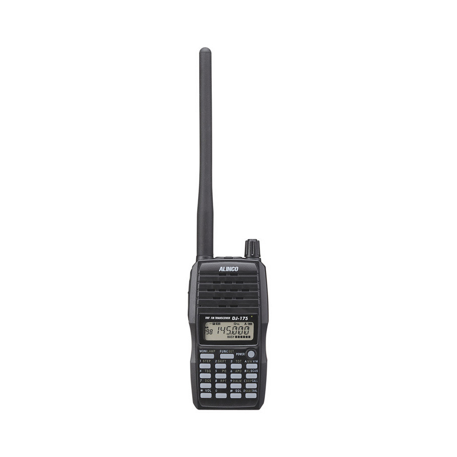
VHF FM TRANSCEIVER DJ-175 T/E/TFH Instruction Manual Thank you for purchasing your new Alinco transceiver. This instruction manual contains important safety and operating instructions. Please read this manual carefully before using the product and keep it for future reference. ALINCO, INC. -
Page 2: Notice / Compliance Information Statement
FOR HOME OR OFFICE USE Information in this document is subject to change without notice or obligation. All brand names and trademarks are the property of their respective owners. Alinco cannot be liable for pictorial or typographical inaccuracies. Some parts, options and/or accessories are unavailable in certain areas. - Page 3 NOTICE / Compliance Information Statement Conformity Information Alinco, Inc. Electronics Division hereby declare on our sole responsibility that the product(s) listed below comply the essential requirements of the Directive 1999/5/EC, The council of 3/9/99 on Radio Equipment and Telecommunication Terminal...
-
Page 4: Warning
Warning Warning To prevent any hazard during operation of Alinco's radio product, in this manual and on the product you may find symbols shown below. Please read and understand the meanings of these symbols before starting to use the product. - Page 5 Warning Do not use multiple radios in very close proximity. It may cause interference and/or damage to the product(s). Risk of explosion if battery is replaced with an incorrect type. Dispose of, or recycle used batteries according to your local regulations. The manufacturer declines any responsibilities against loss of life and property due to a failure of this product when used with or as a part of a device made by third parties.
- Page 6 Warning Do not handle a power supply with a wet hand. It may result in electric shock. Securely plug the power supply to the wall outlet. Insecure installation may result in short-circuiting, electronic shock and/or fire. Do not plug the power supply into the wall socket if the contacts are dirty. Short-circuit and/or overheating may result in fire, electric shock and/or damage to the product.
- Page 7 Warning Caution Environment and condition of use Do not use the product in proximity to a TV or a radio. It may cause interference or receive interference. Do not install in a humid, dusty or insufficiently ventilated place. It may result in electric shock, fire and/or malfunction.
- Page 8 10 kA.). Note also that no car provides adequate protection of its passengers or drivers against lightning as well. Therefore, Alinco will not take responsibility for any danger associated with using its hand-held radios outdoor or inside the car during lightning.
-
Page 9: Introduction
Introduction Introduction Thank you very much for purchasing this excellent Alinco transceiver. Our products are ranked among the finest in the world. This radio has been manufactured with state of the art technology and it has been tested carefully at our factory. It is designed to operate to your satisfaction for many years under normal use. -
Page 10: Table Of Contents
Contents Contents NOTICE / Compliance Information Statement ..........2 Warning.......................4 Introduction ......................9 Contents ......................10 1.Features ......................13 Accessories ......................13 2.Accessories ....................14 Installations ......................14 2.1.1 Antenna ......................14 2.1.2 Hand Strap....................14 2.1.3 Belt Clip .....................15 2.1.4 Battery Pack ....................15 2.1.5 Prevent Short Circuiting the Battery Pack ..........17 2.1.6 Battery-Level Icon..................17 3.Names and Operations of Parts ..............18... - Page 11 Contents Receiving ......................28 4.7.1 Monitor Function..................28 Transmitting .......................28 4.8.1 Selecting the Output Level .................29 5.Useful Functions ...................30 Scan Modes......................30 5.1.1 VFO-Scan....................30 5.1.2 Memory-Scan .....................30 5.1.3 Setting Skip Channels ................31 Keylock .......................31 Tone-Burst ......................31 Naming Memory Channels .................32 5.4.1 Setting Name-Tag..................32 5.4.2 Using the Channel Name Function ............32 Auto-Power-Off (APO) ..................33...
- Page 12 Contents 7.Special Functions..................40 Battery Refresh ....................40 Repeater-Access....................40 8.Set Mode......................41 Set Mode Operation ....................41 Entering the Set Mode ..................41 Available Parameters ..................42 8.3.1 Menu 1 Battery Save (BS) Function ............42 8.3.2 Menu 2 Timer/Busy Scan Setting ..............42 8.3.3 Menu 3 Beep Function ................42 8.3.4 Menu 4 Tone-Burst Frequency Setting ............42 8.3.5...
-
Page 13: Features
1.Features 1. Features This transceiver has the following main features. 39 CTCSS tone squelch 104 DCS digital code squelch Time-Out-Timer Alphanumeric display 4 tone-burst tones (1750, 2100, 1000, 1450Hz) 9 auto dial memories easily accessed from the DTMF keypad with redial function Direct frequency entry from the DTMF keypad A quick "Repeater-Access"... -
Page 14: Accessories
2.Accessories 2. Accessories Installations 2.1.1 Antenna Attaching the Antenna 1. Hold the antenna by its base. 2. Align the grooves at the base of the antenna with the protrusions on the antenna connector. 3. Slide the antenna down and turn it clockwise until it stops. 4. -
Page 15: Belt Clip
2.Accessories 2.1.3 Belt Clip Attaching the Belt Clip Attach the belt clip to the back of the transceiver until Belt clip it clicks. Catch Removing the Belt Clip Push up the catch of the belt clip, and pull it. Belt clip Catch 2.1.4 Battery Pack For the specifications and the charging procedures, please refer to "Battery... - Page 16 2.Accessories Caution • The battery pack isn't fully charged when shipped. It must be charged before use. • Charging should be conducted in a temperature range of 0ºC to +40ºC (+32ºF to +104ºF). • Don't modify, dismantle, incinerate or immerse the battery pack in the water as this can be dangerous.
-
Page 17: Prevent Short Circuiting The Battery Pack
2.Accessories 2.1.5 Prevent Short Circuiting the Battery Pack Be extra cautious when carrying the rechargeable battery pack; short circuiting will produce surge current possibly resulting in fire. DON'T carry with DON'T carry the battery DON'T place in the metals of any type, e.g. pack inside bags made proximity of metals or chains. -
Page 18: Names And Operations Of Parts
3.Names and Operations of Parts 3. Names and Operations of Parts Names and Operations of Keys and Ports... - Page 19 3.Names and Operations of Parts SMA Antenna Attach the whip antenna. If you plan to use an optional antenna, Connector select one that is tuned to the operating frequency. PTT key Press the PTT key to transmit, release to receive. Speaker A speaker is built in.
-
Page 20: Keypad
3.Names and Operations of Parts Keypad Without pressing the FUNC key. While appears after the FUNC key is pressed. Inputs* 1. Channel step setting (page 24). Inputs 2. Offset frequency setting (page 24). Inputs 3. Time-Out-Timer setting (page 33). Inputs 4. Tone Encode/Tone Squelch setting (page 35). -
Page 21: Display (Lcd)
3.Names and Operations of Parts Display (LCD) Appears when the FUNC key is pressed. Indicates the shift (+/-) direction. Appears when setting the CTCSS tone encoder. Appears when setting the tone squelch. Appears when setting the DCS. Displays the frequency and scan operation. Displayed when the frequency or the keypad is locked. -
Page 22: Basic Operation
4.Basic Operation 4. Basic Operation Turning On the Power Hold the key down for a second. To turn off the power, hold the key down until the display turns off. Adjusting the Audio Output (Volume) • There are 21 audio output levels (00~20). •... -
Page 23: Setting The Frequency In The Vfo Mode
4.Basic Operation Setting the Frequency in the VFO Mode The factory default of this unit is the VFO mode. The VFO mode allows you to change the frequency and operating parameters by using the dial and key operations. 4.4.1 Setting the Frequency To Select the VFO Mode key switches between the VFO and Memory mode each time the key is pressed. -
Page 24: Setting The Tuning Step
4.Basic Operation Tuning step Entry completion digit Final digit selection 5.0kHz 1kHz Accept 0 or 5 as valid number. 10.0kHz 10kHz Accept any of 0 to 9 keys. 12.5kHz 10kHz When you input the 10kHz digit, the 1kHz digit is set automatically as follows. -
Page 25: Memory Mode
4.Basic Operation 2. Each time the key is pressed the shift direction changes as indicated below. A (-) means that the TX frequency is lower than the RX frequency. A (+) means vice versa. -0.600 +0.600 OST-OF 3. Rotate the dial while the shift frequency is being displayed. Clockwise: each click increases the frequency by one tuning step. -
Page 26: Recalling A Memory Channel
4.Basic Operation 4.5.2 Recalling a Memory Channel 1. Select the Memory mode by pressing the key. " " and channel number appear on the display to indicate that the unit is in the Memory mode. Repeat to switch between the Memory and VFO modes. 2. -
Page 27: Programmable Parameters In Memory Channels
4.Basic Operation 4.5.5 Programmable Parameters in Memory Channels The following parameters can be stored in each of the memory channels. • Frequency • Offset frequency * • Skip channel setting • Shift direction (+/-) * • Busy channel lockout (BCLO) •... -
Page 28: Receiving
4.Basic Operation Receiving 1. Turn on the unit. 2. Press the key and rotate the dial to adjust the audio level as necessary. 3. Press the key and rotate the dial to adjust the squelch level. 4. Select the frequency that you wish to operate by using the dial or the keypad. When a signal is received on the frequency that you selected, and S-meter are displayed on the LCD, then the received signal can be heard. -
Page 29: Selecting The Output Level
4.Basic Operation 4.8.1 Selecting the Output Level Press the FUNC key, and while is displayed on the LCD, press the key to switch transmission power output. The display changes as follows depending on the output level selected: • is displayed with on the power meter. -
Page 30: Useful Functions
5.Useful Functions 5. Useful Functions Scan Modes The scan function automatically searches the receiving signals. There are 2 modes for scan-resume condition. • Busy Scan: The scan stops when a signal is detected, stays until the signal is gone then resumes scanning. •... -
Page 31: Setting Skip Channels
5.Useful Functions 5.1.3 Setting Skip Channels You can select the memory channels that you wish to skip during the memory-scan. • Press the FUNC key in the Memory mode, and while is displayed, press the key to set the currently selected memory channel as a skip channel. Use the same procedure to clear the skip channel setting. -
Page 32: Naming Memory Channels
5.Useful Functions Naming Memory Channels In the Memory mode, it is possible to display up to 6 alphanumeric characters (Name- tag) instead of conventional frequency display. 5.4.1 Setting Name-Tag 1. Select the memory channel. 2. Press the FUNC key, and while is displayed press the key. -
Page 33: Auto-Power-Off (Apo)
5.Useful Functions Auto-Power-Off (APO) This function prevents an useless battery consumption. 5.5.1 Setting APO Press the FUNC key, and while is displayed on the LCD, press the key. displayed on the LCD, and the Auto-Power-Off function is set. Repeat the same to turn it off. -
Page 34: Lamp
5.Useful Functions Lamp Press the FUNC key, and while is displayed on the LCD, press the MONI key to illuminate the display and DTMF keypad. • The backlight automatically switches off if there is no key operation for 5 seconds. •... -
Page 35: Selective Calling
6.Selective Calling 6. Selective Calling Selective Calling Operations • To communicate only with selected stations, use either the Tone Squelch or the DCS function. The Tone Squelch function unmutes the squelch only when a signal added with one of the matching 39 CTCSS tone frequencies is received. •... -
Page 36: Switching Off The Tone Squelch
6.Selective Calling 6.1.2 Switching Off the Tone Squelch Press the key in Tone Squelch Setting mode to select TCS-OF, then press any key other than the MONI key to complete the setting. 6.1.3 To Differentiate the ENC/DEC Tones It is possible to set the encode and decode tones independently in the Tone Squelch Setting mode. -
Page 37: Changing The Dcs Code
6.Selective Calling 6.2.2 Changing the DCS Code 1. Rotate the dial in DCS Code Setting mode (while " " is displayed). 2. Press any key other than the MONI key to complete the setting. • The same DCS code is set for ENC/DEC, differential setting isn't available. One of the following 104 DCS codes can be selected. -
Page 38: Dtmf Tone Encoding
6.Selective Calling Advantage of DET It enables DCS squelch operation even in poorer signal conditions. Disadvantage of DET When it is activated, suppose 2 stations are sharing the same channel and using the DCS selective-calling technique and transmitting at the same time. After station A with its corresponding DCS is gone, you may still hear station B even his DCS code is different from A, although he can't open your DCS squelch by his signal alone. -
Page 39: Generating The Auto Dialer Codes
6.Selective Calling 3. Use the DTMF key to input the DTMF tones. For example: when programming 123456789, the display changes as follows: 1] –> [ 12] –> [ 123] –> [ 1234] –> [ 12345] –> [123456] –> [234567] –> [345678] –>... -
Page 40: Special Functions
7.Special Functions 7. Special Functions Battery Refresh Repeating improper recharge of the Ni-MH battery pack may cause so-called the "memory effect" that the battery holds less charge. To avoid this, it is always recommended to fully discharge the battery pack then full charge. This function helps discharging the battery pack. -
Page 41: Set Mode
8.Set Mode 8. Set Mode The Set mode is used to customize the various operational parameters of your DJ-175. Set Mode Operation This chart shows the available parameters in the Set mode. Menu Default setting Function BS-1 Battery Save setting TIMER Timer/Busy scan setting FUNC key... -
Page 42: Available Parameters
8.Set Mode Available Parameters 8.3.1 Menu 1 Battery Save (BS) Function This function prevents useless battery consumption by switching the power ON/OFF at a fixed ratio if there is no key operation or receiving signal for a continuous period of 5 seconds or more. 1. -
Page 43: Menu 5 Clock Shift Setting
8.Set Mode 8.3.5 Menu 5 Clock Shift Setting In the unlikely event that you may hear a weak noise always on the same frequency, it may be so-called a CPU-clock noise. Unfortunately this is due to the circuit-design of this product and can't be eliminated, but can be moved away to another frequency. 1. -
Page 44: Menu 7 Tot Penalty Time
8.Set Mode 8.3.7 Menu 7 TOT Penalty Time This parameter determines the time to resume the transmission after the unit is forced to quit transmitting by TOT. 1. TP-OFF is displayed on the LCD. 2. Rotate the dial to change the TOT Penalty Time setting. TP-OFF TP-1 -----... -
Page 45: Menu 10 Dtmf First Digit Burst Time
8.Set Mode 8.3.10 Menu 10 DTMF First Digit Burst Time It often happens that the radios fail to receive the very beginning instant of each communication due to squelch/TSQ/DCS etc. By setting the burst time of the first digit longer, the risk to miss the first DTMF tone will decrease. 1. -
Page 46: Menu 11 Battery Type Setting
8.Set Mode 8.3.11 Menu 11 Battery Type Setting Select the correct battery type from Ni-MH battery pack and Li-ion battery pack in order to display the battery-level icon correctly. 1. BAT-NI is displayed on the LCD. 2. Rotate the dial to select battery type from Ni-MH battery pack (BAT-NI) and Li- ion battery pack (BAT-LI). -
Page 47: Cloning And Packet Operation
9.Cloning and Packet Operation 9. Cloning and Packet Operation Cloning The memory data and customized operational parameters can be transferred from a Master unit to other DJ-175 (Slave units). 9.1.1 Cable Connection • Connect the speaker jacks of the setting sending transceiver and the receiving transceiver using a 3.5 stereo mini plug cord as shown in the diagram. -
Page 48: Master Unit Operation
9.Cloning and Packet Operation 9.1.3 Master Unit Operation 1. In the Clone mode, press the PTT key of the master unit. "SD***" is displayed on the LCD, and starts the data-transfer. 2. After the transfer is completed successfully, "PASS" is displayed. 3. -
Page 49: Packet Operation
9.Cloning and Packet Operation Packet Operation Packet operation is one of the data communication methods, which enables data transmission and reception with a personal computer through an optional TNC unit available from third-parties. 9.2.1 Packet Operation Connections Connect the packet communication TNC (Terminal Node Controller) terminals to the SP (Ø3.5 mm plug) and MIC (Ø2.5 mm plug ) connectors on the top of the transceiver. -
Page 50: Maintenance And Reference
10.Maintenance and Reference 10. Maintenance and Reference 10.1 Troubleshooting Please check the list below before concluding that the unit needs to be serviced. If a problem persists, please reset the unit. The setting/CPU program-related troubles are often resolved by the reset. Symptom Possible Cause Action... -
Page 51: Resetting
10.Maintenance and Reference 10.2 Resetting 10.2.1 All Resetting When you reset the unit, all settings are returned to the initial factory settings. The reset deletes the programmed memory channels also. 1. Turn on the unit with the FUNC and keys pressed together. 2. -
Page 52: Options
EMS-47 Speaker Microphone with Audio Control EMS-59 Speaker Microphone *More accessories may be available. Please visit alinco.com for details. NOTE: FOR EUROPEAN USERS: Please be advised that some of the accessories listed above are not RoHS compliant at the moment this manual has been edited, and they are intended for the sales to where RoHS order is not effective. -
Page 53: Using The Chargers
10.Maintenance and Reference 10.3.2 Using the Chargers Caution Please also read the "Warning" (page 4 of this manual) and the safety instruction that is included in the accessories' package before operating for your safety. Charging with the EDC-165 (Trickle Charger) Please make sure that following items are included in the package. -
Page 54: Specifications
10.Maintenance and Reference 4. After charging time is elapsed (page 52), remove the battery pack from the basket. The red indicator stays turned on as long as the pack is mounted on the basket regardless of the charging status. Specifications EBP-72 Input Voltage DC 12.0V 70mA... - Page 55 10.Maintenance and Reference 3. Mount the battery (with or without being attached to the unit) in the basket as shown. Turn off the unit while charging. The red indicator on the basket turns on and charging starts. Indicator 4. The red indicator turns off when the charge is completed. Remove the battery pack from the basket.
-
Page 56: Specifications
11.Specifications 11. Specifications General Frequency range TX144~147.995MHz * 144~147.995MHz RX136~173.995MHz * 144~147.995MHz TX144~145.995MHz * 144~145.995MHz RX144~145.995MHz * 144~145.995MHz TFH: TX136~173.995MHz * 150~173.995MHz RX136~173.995MHz * 150~173.995MHz *Guaranteed range per specifications Modulation: F3E (FM), F2D* *T/E models only Channel steps: 5, 10, 12.5, 20, 25 & 30KHz Memory channels: 200 channels + 1 CALL channel + 1 Repeater-Access function memory... - Page 57 11.Specifications Transmitter Output power (Approx.): 5W (High)/2W (Middle)/0.5W (Low) Modulation: Variable reactance frequency modulation Max. deviation: ±5KHz (±2.5KHz)** Spurious emission: -60dB or less Receiver Receive system: Double conversion superheterodyne Intermediate frequencies: 1st: 21.7MHz/2nd: 450KHz Sensitivity (12dB SINAD): -14dBµ (0.2µV) Selectivity: -6dB: 12KHz or more/-60dB: 26KHz or less (-6dB: 6KHz or more/-60dB: 14KHz or less)** 500mW (8 Ω, MAX)
- Page 58 The following table lists available characters.
- Page 60 Basic Operation Useful Functions ALINCO, INC. Yodoyabashi Dai-Bldg 13F, 4-4-9 Koraibashi, Chuo-ku, Selective Calling Osaka 541-0043 Japan Phone:06-7636-2362 Fax:06-6208-3802 http://www.alinco.com Special Functions E-mail:export@alinco.co.jp Set Mode Cloning and Packet Operation Maintenance and Reference Specifications Printed in Japan Copyright Alinco, Inc. PS0572/FNNL-NL...