Advertisement
Installation & Operating Manual
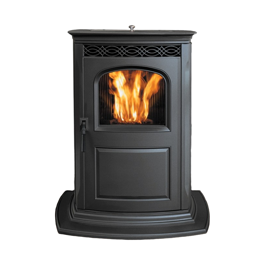
The Harman Accentra-2 Pellet Stove
"Ce manuel est disponible en Français sur demande"
R4
SAFETY NOTICE
PLEASE READ THIS ENTIRE MANUAL BEFORE YOU INSTALL AND USE YOUR NEW ROOM HEATER. FAILURE TO
FOLLOW INSTRUCTIONS MAY RESULT IN PROPERTY DAMAGE, BODILY INJURY, OR EVEN DEATH.
FOR USE IN THE U.S. AND CANADA. SUITABLE FOR INSTALLATION IN MOBILE HOMES
IF THIS HARMAN ACCENTRA PELLET STOVE IS NOT PROPERLY INSTALLED, A HOUSEFIRE MAY RESULT. FOR
YOUR SAFETY , FOLLOW INSTALLATION DIRECTIONS.
CONTACT LOCAL BUILDING OR FIRE OFFICIALS ABOUT RESTRICTIONSAND INSTALLATION INSPECTION
REQUIREMENTS IN YOUR AREA.
CONTACT YOUR LOCAL AUTHORITY (SUCH AS MUNICIPAL BUILDING DEPARTMENT, FIRE DEPARTMENT, FIRE
PREVENTION BUREAU, ETC.) TO DETERMINE THE NEED FOR A PERMIT.
CETTE GUIDE D'UTILISATION EST DISPONIBLE EN FRANCAIS. CHEZ VOTRE CONCESSIONNAIRE DE HARMAN ST OVE
COMPANY.
SAVE THESE INSTRUCTIONS.
Advertisement
Table of Contents

Related Manuals for Harman Stove Company Accentra 2


Summary of Contents for Harman Stove Company Accentra 2
-
Page 1: Safety Notice
FOLLOW INSTRUCTIONS MAY RESULT IN PROPERTY DAMAGE, BODILY INJURY, OR EVEN DEATH. FOR USE IN THE U.S. AND CANADA. SUITABLE FOR INSTALLATION IN MOBILE HOMES IF THIS HARMAN ACCENTRA PELLET STOVE IS NOT PROPERLY INSTALLED, A HOUSEFIRE MAY RESULT. FOR YOUR SAFETY , FOLLOW INSTALLATION DIRECTIONS. -
Page 2: Table Of Contents
SERIAL NUMBER SAFETY NOTICE: IF THIS HARMAN ACCENTRA PELLET STOVE IS NOT PROPERLY INSTALLED. A HOUSE FIRE MAY RESULT. FOR YOUR SAFETY, FOLLOW THE INSTAL- LATION DIRECTIONS CONTACT LOCAL BUILDING OR FIRE OFFICIALS ABOUT RESTRICTIONS AND INSTALLATION INSPECTION REQUIREMENTS IN YOUR AREA. - Page 3 Automatic Ignition/Operation The Accentra pellet stove is more than just automatic ignition, it is also automatic temperature control. The automatic system will allow the fire size to be adjusted to match the heating needs and even put the fire out if necessary. If heat is needed after the fire is out, the Accentra will automatically re-ignite and adjust the fire size to match the heating need.
- Page 4 7. Setting the feed adjuster # for maximum burn: With the unit burning in "AUTO", turn to "Stove Mode" and put the fan on "H". Set the Temperature Dial to #7. Allow the unit to burn for about 30 minutes and check ash on front of burn pot.
-
Page 5: Manual Operation
The Accentra Pellet Stove is capable of manual operation. This also allows the opera- ..tor to manually control operation during an emergency (i.e. igniter failure, when using a 502H battery backup, or when using certain generators.) The unit can be switched between "AUTO" and "MANUAL" at any time during operation. - Page 6 7. Setting the feed adjuster # for maximum burn: With the unit burning in "AUTO", turn to "Stove Mode" and put the fan on "H". Set the Temperature Dial to #7. Allow the unit to burn for about 30 minutes and check ash on front of burn pot.
-
Page 7: Esp Control
50 minutes. A six blink status may be set if the stove is allowed to run out of pellets. To reset, turn mode selector to "OFF" then back on to the desired mode. If the unit was not out of pellets, see Troubleshooting section, Page 24, for more details. - Page 8 This can be a minimum of a 20 gauge sheetmetal plate, ceramic tile with grouted joints, a UL listed stove board, or a Harman Cast Iron floor protec- . The Harman Cast Iron Floor Protector is equal to the minimum dimensions, which are 24 allows for a 2"...
- Page 9 IMPORTANT NOTE: The Accentra unit is shipped bolted to the skid through two holes in the cast base plate. If these holes are not used to lag the unit to the floor these holes must be filled with the 3/8" x 1/ 2"...
- Page 10 Young children should be carefully supervised when they are in the same room as the stove. Clothing and other flammable materials should not be placed on or near the Accentra Pellet Stove.
- Page 11 Low Draft Voltage Adjustment Fig.17 These units are pre-tested at the factory with exactly 120 Volts A.C., 60 Hz. They are checked and adjusted for firebox tightness, gasket leakage, motor operation and ignitor operation. The Accentra is then factory set at a high adjustment. NOTE: Low draft adjustment may be required.
- Page 12 Room Sensor and Rear Shield Installation Room Sensor Installation Fig. 19 The room sensor is a small temperature sen- sor on the end of a 60" gray wire. This sensor is installed much like a standard wall thermostat. Be- cause it is so small, it can be hidden along the trim of a doorway or even up the leg of a coffee table.
- Page 13 Be sure to use a starting collar to attach the venting systen to the stove. The starting collar must be sealed to the stove with high temp sili- cone caulking. Pellet venting pipe (also known as PL vent is constructed of two layers with air space between the layers.
-
Page 14: Venting
#1 Preferred method This method provides excellent venting for nor- mal operation and allows the stove to be installed closest to the wall. Two and a half inches from the wall is safe; however, three inches allows better access to remove the rear panel. - Page 15 Venting Fig.27 Fig.28 #4 Installing into an existing chimney (US only) This method provides excellent venting for nor- mal operation. This method also provides natural draft in the event of a power failure. If the chimney condition is questionable you may want to install a liner as in method #7.
- Page 16 Venting Fig.29 Fig.30 #6 Installing into an existing fireplace chimney (US and Canada) This method provides excellent venting for nor- mal operation. This method also provides natural draft in the event of a power failure. In Canada and some places in the US it is re- quired that the vent pipe extend all the way to the top of the chimney.
- Page 17 Storm collar 12" min. Flashing 3" min. 3" min. 3" min. PL vent manufacturer's No insulation or fi re stop s pa ce r an d other combustible support ma te ri al s allowed within 3" of the PL ve nt pipe.
- Page 18 Requirements for Terminating the Venting WARNING: Venting terminals must not be re- cessed into a wall or siding. NOTE: Only PL vent pipe wall pass-throughs and fire stops should be used when venting through combustible materials. NOTE: Always take into consideration the ef- fect the prevailing wind direction or other wind cur- rents will cause with flyash and /or smoke when plac- ing the termination.
-
Page 19: Maintenance
Maintenance - Cleaning Glass on View Door The unit should be out and cool to clean the door glass. It may not always be possible to allow the unit to cool off before cleaning. Therefore, if the unit is turned to the lowest setting about 1 hour before cleaning, it will make it possible to clean the glass with the unit in operation. - Page 20 Cleaning Internal Components 1. Remove the two heat exchanger covers. See Fig. 35. These covers are made of cast iron and are held into place with a swing latch in the upper right and left corners. See Fig 36. Swing the latch upward far enough to r elease the top edge of the heat exchanger cover.
- Page 21 Maintenance - Cleaning (Cleaning Internal Components Cont'd) 2. Remove the combustion intake assembly. See Fig. 35. The combustion intake assembly is held into place with two swing latches. See Fig. 37. Swing each latch until it hangs down away from the retainer stud.
- Page 22 Fig. 39 Fig. 40 Fig. 41 Viewed from below through the ash pan opening. Maintenance - Burn Pot Burn Pot Cleaning and Maintenance 1. Scrape the top holed surface and sides of the burn pot down to auger tube.(Fig 39) It is not necessary to completely remove all material from the burn pot.
-
Page 24: Trouble-Shooting
A vacuum cleaner is handy to remove the resi- due. Be sure the stove is cold if you use a vacuum. Carbon buildup can be scraped loose with the fire burning using the special tool provided with your stove. -
Page 25: Specifications
Specifications Weight Blower Hopper Capacity Fuel Outside Air Size Fuse Rating BTU Range Feed Rate Flue Size Maximum Wattage Start Cycle Wattage Normal Run Wattage 350 lbs. 150 cfm 50 lbs. Wood Pellets 2 3/8 inches 5 amp 0 to 40,000 .75 lbs./hr. - Page 26 Accentra Wiring Diagram...
- Page 27 Accentra Feeder Parts...
-
Page 28: Wiring Diagram
Accentra Parts List Description Hopper Lid Gasket Ignitor Element Assembly Wiring Harness Burn Pot Weldment Right Feeder Shield w/sound proof Left Feeder Shield w/sound proof Heat Exchanger Cover (2) Arrow Scraper Flame Guide Gear Motor Thermister Probe Room Sensor Circuit Board G4220G V5.0 Feeder Switch Jumper 3"... -
Page 29: Warranty
MERCHANTABILITY, OR WARRANTY OF FITNESS FOR A PARTICULAR PURPOSE. No employee, agent, dealer, or other person is authorized to give any warranty on behalf of Harman Stove Company. This warranty does not apply if the product has been altered in any way after leaving the factory. Harman Stove Company and its agents assume no liability for “resultant damages of any kind”...