Lopi Answer Owner's Manual
Wood stove / inbuilt
Hide thumbs
Also See for Answer:
- Owner's manual (48 pages) ,
- Manual (48 pages) ,
- Owner's manual (48 pages)
Table of Contents
Advertisement
Quick Links
Download this manual
See also:
Owner's Manual
Answer Wood
Stove / Inbuilt
SAFETY NOTICE:
If this appliance is not properly installed, a house fire may result.
For your safety, follow the installation directions. Contact local
building or fire officials about restrictions and installation
inspection requirements in your area.
Dragon Wholesaling Pty. Ltd.
Unit 2, 16 Lexington Drive
Bella Vista NSW 2153
Australia
Copyright 2011, Travis
Industries, Inc.
$10.00
100-01278_000
4111128
Owner's Manual
Save these instructions
for future reference
Tested By:
AMDEL
8/26 Stirling St.
Thebarton, 5031, South Australia
TESTED TO: AS/NZS 4013:1999
REPORT NUMBER: L4506/94
Advertisement
Table of Contents

Related Manuals for Lopi Answer


Summary of Contents for Lopi Answer
-
Page 1: Safety Notice
Answer Wood Stove / Inbuilt Owner's Manual Save these instructions for future reference SAFETY NOTICE: If this appliance is not properly installed, a house fire may result. For your safety, follow the installation directions. Contact local building or fire officials about restrictions and installation inspection requirements in your area. -
Page 2: Introduction
Introduction Introduction We welcome you as a new owner of a Answer wood-burning stove. In purchasing a Answer you have joined the growing ranks of concerned individuals whose selection of an energy system reflects both a concern for the environment and aesthetics. The Answer is one of the finest appliances the world over. -
Page 3: Table Of Contents
Chimney Connector Requirements ....9 Door Parts ............30 Chimney Requirements ......... 10 Lopi Republic Door ..........30 Replacing the Glass ..........30 Chimney Termination Requirements ... 11 Replacing the Door Gasket ......... 30 ... - Page 4 Safety Precautions The viewing door must be Gasoline or other flammable closed and latched during liquids must never be used to operation. start the fire or "Freshen Up" the fire. Do not store or use gasoline or other flammable Never block free airflow through liquids in the vicinity of this the air vents on this appliance.
- Page 5 Safety Precautions Never try to repair or replace any part of this appliance unless Do not place clothing or other instructions are given in this flammable items on or near this manual. All other work must be appliance. done by a trained technician. Hot while in operation.
-
Page 6: Installation Options
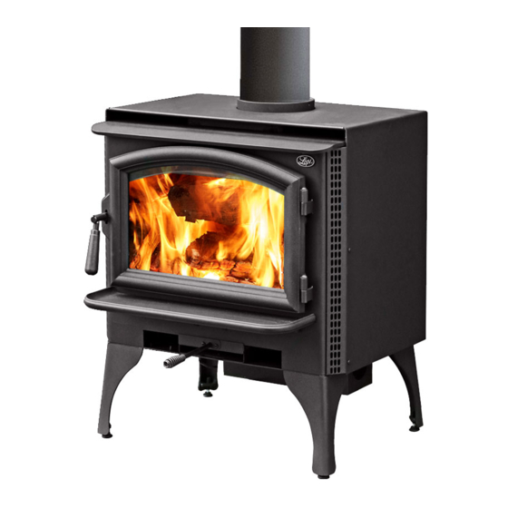
Features & Specifications Installation Options Features Freestanding EPA Phase II Approved Freestanding Hearth Stove .05 Cubic Meter Firebox Volume Single Operating Control Accepts Logs Up to 457mm Long Steel Plate Construction 9.5mm to 6mm ... -
Page 7: Planning The Installation
Stove Installation (for qualified installers only) SAFETY NOTICE: Please read this entire manual before you install and use your new room heater. Failure to follow instructions may result in property damage, bodily injury, or even death. Contact local building or fire officials about restrictions and installation inspection requirements in your area. -
Page 8: Floor Protection Requirements
Stove Installation (for qualified installers only) Floor Protection Requirements • Stove must be placed on the Travis Industries legs or pedestal. • Floor protection must extend to the sides, rear, and front of the stove (see “Clearances” below for minimum floor protection). NOTE: When installed with reduced-clearance connector, the clearance to the backwall may be less than the floor protection requirement. -
Page 9: Chimney Connector Requirements
Stove Installation (for qualified installers only) Chimney Connector Requirements The chimney connector must be 6” (150mm) diameter and stainless steel. NOTE: Aluminum or galvanized steel is not allowed – these materials cannot withstand the flue temperatures and may give off toxic fumes when heated. ... -
Page 10: Chimney Requirements
Stove Installation (for qualified installers only) Chimney Requirements DO NOT CONNECT THIS UNIT TO A CHIMNEY FLUE SERVING ANOTHER APPLIANCE. DO NOT CONNECT TO OR USE IN CONJUNCTION WITH ANY AIR DISTRIBUTION DUCTWORK UNLESS SPECIFICALLY APPROVED FOR SUCH INSTALLATIONS. ... -
Page 11: Chimney Termination Requirements
Stove Installation (for qualified installers only) Chimney Termination Requirements Must have an approved cap (to prevent water from entering). Must not be located where it will become plugged by snow or other material. Must terminate at least 3' (914mm) above the roof and at least 2' (610mm) above any portion of the roof within 10' (3.04M) - see Figure 5. -
Page 12: Standard Ceiling With A Factory Built Chimney
Stove Installation (for qualified installers only) Chimney Cap Standard Ceiling (See the section "Chimney with a Factory Termination Requirements" Follow the chimney Built Chimney for more details) manufacturer's instructions and clearances for roof penetrations. A storm collar and flashing are required Chimney Sections (some require a radiation shield). -
Page 13: Exterior Factory Built Chimney
Stove Installation (for qualified installers only) Exterior Factory Follow the chimney Chimney Cap Built Chimney manufacturer's (See the section "Chimney instructions and Termination Requirements" clearances for roof for more details) penetrations. A storm NOTE: collar and flashing are Exterior chimneys are required (some Chimney Sections subject to greater... -
Page 14: Interior Or Exterior Masonry Chimney
Stove Installation (for qualified installers only) Interior or Exterior NOTE: The chimney must have a Masonry Chimney clay tile liner. If it does not, the installation must use a positive connection (full reline). The entire Clay Liner NOTE: fireplace and chimney must be clean, undamaged, and meet all Must maintain This type of installation is... -
Page 15: Safety Notice
Inbuilt Installation (for qualified installers only) SAFETY NOTICE: Please read this entire manual before you install and use your new room heater. Failure to follow instructions may result in property damage, bodily injury, or even death. Contact local building or fire officials about restrictions and installation inspection requirements in your area. -
Page 16: Fireplace Requirements
Inbuilt Installation (for qualified installers only) Fireplace Requirements Figure 12 shows the minimum size requirements for the type of fireplace used. Minimum Fireplace Size Masonry Fireplace Depth 350mm Width (front) 620mm Width (rear) 620mm Height (front) 550mm Figure 12 Fireplace Altered Tag Attach the "This fireplace has been altered..."... -
Page 17: Insert Placement Requirements
Inbuilt Installation (for qualified installers only) Insert Placement Requirements The insert must be placed so that no combustibles are within, or can swing within (e.g. drapes, doors), 36" (915mm) of the front of the insert Insert and hearth must be installed on a level, secure floor ... -
Page 18: Leveling Bolt Installation
Inbuilt Installation (for qualified installers only) Leveling Bolt Installation Two leveling bolts are included to level the insert if the fireplace has a stepped-up hearth. To install, raise the rear of the insert up and insert the leveling bolts into the holes in the rear corners of the insert. Adjust the bolts until they extend the same height as the hearth steps up. - Page 19 Inbuilt Installation (for qualified installers only) Block-Off Plate Installation Whenever this appliance is installed with a direct connection a block-off plate, or other non-combustible seal-off device (e.g. damper adapter), will need to be installed. This device is used to seal the chimney, insuring no smoke enters the home and providing the chimney system with a seal to promote draft.
- Page 20 Inbuilt Installation (for qualified installers only) Install a non-combustible Insert with Cap (prevents water cover plate to prevent water Positive from entering) from entering the chimney Connection NOTE: Flue Liner Most factory-built The liner must be chimney manufacturers stainless steel make stainless steel connector or flexible chimney liners, either...
-
Page 21: Before Your First Fire
Operating Your Appliance Safety Notice If this appliance is not properly installed, a house fire may result. For your safety, follow the installation directions. Contact local building or fire officials about restrictions and installation inspection requirements in your area. Read and follow all of the warnings on pages 4 and 5 of this manual. Before Your First Fire Verifying the Installation Before starting the stove, verify that the stove is properly installed and all of the requirements in this... -
Page 22: Starting A Fire
Operating Your Appliance Starting a Fire Since the dawn of time man has debated the best way to start a fire. Some use the boy-scout "tee-pee", some prefer the "tic-tac-toe" stack. Either way, review the hints and warnings below to ensure proper fire starting. -
Page 23: Adjusting The Burn Rate
Operating Your Appliance Adjusting the Burn Rate Use the air control slider to control the burn rate of the stove. See the illustration below for details. Use the air control to change the burn rate. Low Burn High Burn (air control closed) (air control open) Approximate Air Control Settings Overnight Burn... -
Page 24: Optional Blower Operation
Operating Your Appliance Optional Blower Operation The blower is available to assist the convection chamber in distributing heat to your home. The directions below detail the options you have with the blower and the best method for operation. HIGH Turn the dial all the way counter- The high position is all the way counter- Turn the dial all the clockwise until it clicks off. -
Page 25: Hints For Burning
Operating Your Appliance Hints for Burning Get the appliance hot before adjusting to low burn Use smaller pieces of wood during start-up and high burns to increase temperature Use larger pieces of wood for overnight or sustained burns ... -
Page 26: Troubleshooting
Operating Your Appliance Troubleshooting Problem Possible Cause Smoke Enters Room During Open the air control (pg. 23). Start-Up Cold Air Blockage - burn a piece of newspaper to establish a draft. If the flame is not getting enough air, a small crack in the door is all that is needed. -
Page 27: Daily Maintenance (While Stove Is In Use)
Maintaining Your Appliance Failure to properly maintain and inspect your appliance may reduce the performance and life of the appliance, void your warranty, and create a fire hazard. Establish a routine for the fuel, wood burner and firing technique. Check daily for creosote build-up until experience shows how often you need to clean to be safe. -
Page 28: Monthly Maintenance (While Appliance Is In Use)
Maintaining Your Appliance Monthly Maintenance (while appliance is in use) Make sure the appliance has fully cooled prior to conducting service. Door and Glass Inspection The door must form an air-tight seal to the firebox for the stove to work correctly. Inspect the door gasket to make sure it forms an air-tight seal to the firebox. -
Page 29: Yearly Maintenance
Maintaining Your Appliance Yearly Maintenance Make sure the appliance has fully cooled prior to conducting service. Touch-Up Paint Included with the owner's pack of this appliance is a can of Stove-Brite® paint. To touch up nicks or dulled paint, apply the paint while the appliance is cool. -
Page 30: Door Parts
Maintaining Your Appliance Door Parts Lopi Republic Door 1/8” Hex Wrench # 20 Torx Driver NOTE: Place the glass gasket around the perimeter of the door retainer. 9/16" Wrench NOTE: Glue the door gasket to the door retainer. ID #... -
Page 31: Firebox Parts
Maintaining Your Appliance Firebox Parts ID # Description Part # ID # Description Part # Baffle Support "S" Bar 99900294 Air Tube with Sleeve 98900232 NOTE: The Australian heater has only one air tube, at the rear of the firebox. Air Tube Roll Pins 98900357 Air Tube Retainer Sleeve... -
Page 32: Air Tube Removal & Replacement
Maintaining Your Appliance Air Tube Removal & Replacement All three air tubes are identical. Air Tube Collar Air Tube Remove the left pin on the air tube collar Roll Pin Slide the air tube to the left, swing it down and remove from the firebox. Baffle Removal &... -
Page 33: Warranty
Limited 7 Year Warranty Warranty To register your Warranty, complete the enclosed warranty card and mail it within ten (10) days of the appliance Dragon Wholesaling Pty. Ltd., Unit 2, 16 Lexington Drive, Bella Vista NSW 2153, purchase date to:. Australia . - Page 34 Limited 7-Year Warranty CONDITIONS & EXCLUSIONS 1. This new appliance must be installed by a qualified installer. It must be installed, operated, and maintained at all times in accordance with the instructions in the Owner’s Manual. Any alteration, willful abuse, accident, neglect, or misuse of the product shall nullify this warranty. 2.
-
Page 35: Listing Label
Listing Label Listing Label The listing label (safety label) is attached to the back of the stove. A copy is shown below. LOPI ANSWER FREESTANDING TESTED BY: AMDEL THEBARTON SOUTH AUSTRALIA 1999 MAXIMUM AVERAGE HEAT OUTPUT BURNING HARDWOOD = 10.9 KW OVERALL AVERAGE EFFICIENCY BURNING HARDWOOD = 61.6%... -
Page 36: Door Shell Installation
Optional Equipment Door Shell Installation Part Numbers: Black # 99300195, Brass # 9930096, Pewter # 99300197 Remove the door retainer shipping latch following the directions below. Standard Screwdriver Rotate this shaft 1/4 turn clockwise until the door unlatches. Swing the door retianer open. Remove and discard the shipping latch and nut. - Page 37 Optional Equipment Attach the retainer to the shell following the directions below. Make sure the door retainer is centered on the door shell. You can gauge the alignment by looking at the gaps here. 1/8” Hex Wrench Once the door is aligned, tighten the two set screws on the bottom of the door shell to secure the door retainer.
-
Page 38: Stove Leg Installation
Optional Equipment Stove Leg Installation Part Numbers: Brass # 99200500, Cast Black # 99200800, Sculptured Steel # 99200105 Raise the stove 8" (use lumber). Attach each leg following the instructions below. Attach each leg to the stove by inserting a bolt and washer through the hole or slot in the leg and into the threaded hole on the stove. -
Page 39: Pedestal (Part # 99200106)
Optional Equipment Pedestal (Part # 99200106) If using outside air with the pedestal, follow the directions below under "Using Outside Air with the Pedestal" prior to installing the pedestal. Use a 9/16" wrench to attach the two pedestal bolts to the bottom of the stove. Stove The lag bolts and washers... -
Page 40: Rear Blower Installation (Part # 99000138)
Optional Equipment Rear Blower Installation (Part # 99000138) The rear blower improves heat transfer by pushing heated air through the convection channel. Operating instructions are described in the section "Blower Operation". The stove should be in place with the legs installed prior to installing the rear blower. Follow the directions below to install the thermodisk. -
Page 41: Outside Air Boot Installation (Part Number 99200134)
Optional Equipment Outside Air Boot Installation (Part number 99200134) The outside air boot routes outside air to the stove for combustion. Refer to the section "Outside Air Requirements" for installation concerns. The directions below detail installation. Install the cover plate following the directions below (use the cover plate that is 6-1/2" wide). The cover plate prevents combustion air from entering the front of the stove. -
Page 42: Surround Panels
Optional Equipment Surround Panels Rectangular Panels: SURROUND PANEL SIZE HEIGHT WIDTH 203mm 718mm 1019mm 254mm 768mm 1121mm Installation Instructions With the insert 12” from the fireplace, install the side surround panels (see the directions below). Pry the button plugs Attach the side from both sides of the surround panels insert. -
Page 43: Insulation Installation (Required Only For Face Seal Installations)
Optional Equipment 2. Adjust the position of the side panels so they are: 1) flush with the bottom of the insert; 2) both the same distance back from the front of the insert; 3) perpendicular to the floor (use the top panel, if necessary, to judge alignment). -
Page 44: Front Blower (Part # 99000128)
Optional Equipment Front Blower (part # 99000128) To Switch The Power Cord To The Left Side: Use a pair of pliers to disconnect the strain relief which holds the power cord in place. With the power cord slackened, the molex connectors that attach the power cord to the blower assembly may be disconnected. - Page 45 Optional Equipment © Travis Industries 100-01278 4111128...
- Page 46 Index Installation Options ..........6 Adjusting the Burn Rate ........17 Interior or Exterior Masonry Chimney ....14 Air Tube Removal & Replacement ....26 Listing Label ............. 29 Approximate Air Control Settings ..... 17 Monthly Maintenance ........22 Baffle Removal & Replacement ....... 26 Normal Operating Sounds .......