Advertisement
Table of Contents
- 1 Specifications
- 2 Safety Warnings and Precautions
- 3 Installation
- 4 Operation
- 5 Cutting Procedures
- 6 Maintenance
- 7 Lubrication Points
- 8 Headstock Parts List
- 9 Please Read the Following Carefully
- 10 Bed Parts List
- 11 Tailstock Parts List
- 12 Saddle Parts List
- 13 Apron Parts List
- 14 Gear Box Parts List
- 15 Limited 1 Year / 90 Day Warranty
- Download this manual
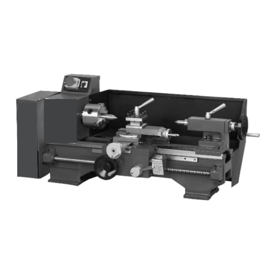
8" x 12" lathe
assembly and operating instructions
read this material before using this product.
Failure to do so can result in serious injury.
saVe this manual.
Copyright
2001 by Harbor Freight Tools
©
contained herein may be reproduced in any shape or form without the express written consent of Harbor Freight
Tools. Diagrams within this manual may not be drawn proportionally. Due to continuing improvements, actual
product may differ slightly from the product described herein. Tools required for assembly and service may not
be included.
For technical questions or replacement parts, please call 1-800-444-3353.
Revised 09g
distributed exclusively by harbor Freight tools
3491 Mission Oaks Blvd., Camarillo, CA 93011
Visit our website at: http://www.harborfreight.com
. All rights reserved. No portion of this manual or any artwork
®
44859
.
®
Advertisement
Table of Contents

Related Manuals for Central Machinery CENTRAL MACHINERY 44859


Summary of Contents for Central Machinery CENTRAL MACHINERY 44859
- Page 1 8” x 12” lathe assembly and operating instructions distributed exclusively by harbor Freight tools 3491 Mission Oaks Blvd., Camarillo, CA 93011 Visit our website at: http://www.harborfreight.com read this material before using this product. Failure to do so can result in serious injury.
-
Page 2: Specifications
Weight note: the splash guard shown in the cover page photo is not included. it can be ordered from harbor Freight tools using sKu 26962. You will need the manual for the safety warnings and precautions, assembly instructions, operating and maintenance procedures, parts list and diagram. Keep your invoice with this manual. - Page 3 Keep children away. Children must never be allowed in the work area. Do not let them handle machines, tools, or extension cords. store idle equipment. When not in use, tools must be stored in a dry location to inhibit rust. Always lock up tools and keep out of reach of children. do not force tool.
- Page 4 When unpacking, check to make sure that all the parts are included. Refer to the Accesso- ries list in the Specifications table, and the Parts List. If any parts are missing or broken, please call Harbor Freight Tools at the number on the cover of this manual as soon as possible.
-
Page 5: Installation
(see Lubrication section) before running the machine. This 8 x 12 inch Lathe is capable of machining metal and nonmetallic stock by cutting, drilling, and milling. It can cut circular surfaces, both inside and out, cones, mill planes or grooves, and other cutting functions depending on the tools used. -
Page 6: Cutting Procedures
Do not open drive cover while in operation. Always remove chuck key from chuck. Do not attempt to adjust or remove tools when lathe is in operation. Always keep cutting tools sharp. cutting procedures The instructions that follow are basic operational procedures. It is assumed that the opera- tor understands lathe operation and it’s capabilities. - Page 7 To manually cut a cone, determine the taper requirement and turn the small cutter rest to the desired slope on the workpiece. Retighten the cutter rest. Press the green On button to start the lathe. Turn the Straight Lever (F) clockwise to make the cut.
- Page 8 The Fixed Shaft Bolt (825) under the spindle is used for right hand cutting and threading. The set of Fixed Shaft Bolts in the accessory kit is used in combination with the original set of Shaft Bolts to reverse the rotation of the long leadscrew for left-handed threading and cutting.
-
Page 9: Maintenance
Using compressed air, blow off all dirt and particles after using. Keep all tools sharp. Cover Lathe when not in use. Periodically, check all bolts and nuts for tightness. lubrication Lubricate the Lathe daily using an appropriate machine oil from a forced-feed oil can. SKU 44859 maintenance Page 9... -
Page 10: Lubrication Points
ITEM See lubrication location illustration on next page Fix bolt of intermediate gear Leadscrew support Cutter rest screw Cutter rest carriage Tailstock sleeve Tailstock leadscrew Leadscrew support Sync. counter-pulley over shaft Change gear, shaft bolt Change gear Bed guides Saddle Carriage Saddle leadscrew Saddle Carriage Bed guides... - Page 11 Page 11 SKU 44859...
-
Page 12: Headstock Parts List
ITEM # Front Oil Ring Roller Bearing Oil Ring Screw Front Panel Rear Oil Ring Tube Separator Spindle Pulley Spindle Gear Screw Switch Box Headstock Plat Key Screw Spindle Cover note: Some parts are listed and shown for illustration purposes only and are not available individually as replacement parts. - Page 13 headstock assembly drawing Page 13 SKU 44859 motor and pulley drive parts list...
- Page 14 motor and pulley drive parts list item # name 1501 1502 Synchronized Counter Pulley 1503 Slide Bearing 1504 Shaft 1505 Over Plate 1506 Washer 1507 Washer 1508 1509 1510 1511 Screw 1512 Motor Guard Assem- 1513 Bolt 1514 Washer 1515 Washer 1516 Fan-Support...
- Page 15 motor and pulley drive assembly drawing Page 15 SKU 44859...
-
Page 16: Bed Parts List
item # Left Support of Lead Screw Flat Key Screw Screw Oil Cup Right Support of Lead Screw Screw Laer-pin Lead Screw Rack Screw Adjusting Disc Spring Pin SKU 44859 bed parts list name A 4 B 5 remarKs 4 x 6 A 400B 555 M8 x 12 M5 x 16... - Page 17 bed assembly drawing Page 17 SKU 44859...
-
Page 18: Tailstock Parts List
item # Screw Washer Tailstock Body Single Row Radial Ball Bearing Tailstock Leadscrew Tailstock Sleeve Washer Bolt Hand Lever Force Feed Oil Cup T-type Flat Key Screw Screw Tailstock End Cover Cylinder Pin Spring Bow Handwheel Hand Lever Bolt Hand Lever Sleeve Index Ring Bolt Tailstock Clamp Plate... - Page 19 tailstock assembly drawing Page 19 SKU 44859...
- Page 20 item # Index Piece Rivet Cutter Rest Revolving Disc Rest Bolt Screw Screw Position Pin Square Cutter Rest Screw Hand Lever Hand Lever Base Washer Spring Cutter Rest Carriage Pad Iron Cylinder Pin Cutter Rest Carriage Lead Flat Key Force Feed Oil Cup Leadscrew Support Screw Spring Bow...
- Page 21 rest assembly drawing Page 21 SKU 44859...
-
Page 22: Saddle Parts List
item # Screw Washer Oil Cup Middle Saddle Large Saddle Screw Screw Screw Protecting panel and oil-stopping falt Screw Protecting panel and oil-stopping falt Screw Pad Iron Protecting panel and oil-stopping falt Screw Rear-clamp plate Pad Iron Screw Screw Protecting panel and oil-stopping falt Flat Key Screw Pring Bow... - Page 23 saddle assembly drawing Page 23 SKU 44859...
-
Page 24: Apron Parts List
item # Slotted Disc Taper Pin Shaft Sleeve Case Bolt Revolving Shaft Hand Lever Steel Ball Spring Positioning Lever Screw Screw Screw Flanged Shaft Sleeve Taper Pin Hand Lever Sleeve Hand Lever Sleeve Handwheel Screw Small Flanged Shaft Sleeve Small Gear Shaft Shaft Sleeve Gear Shaft Sleeve... - Page 25 apron assembly drawing Page 25 SKU 44859...
-
Page 26: Gear Box Parts List
item # Change Gear Change Gear Change Gear Change Gear Change Gear Change Gear Change Gear Change Gear Change Gear Washer Check Ring Screw Change Gear Change Gear Shaft Bolt Oil Cup Change Gear Change Gear Open Washer Rolling Bearing Intermediate Gear Check Ring Outer Washer... - Page 27 gear box assembly drawing drive system parts list Page 27 SKU 44859...
- Page 28 item # name Synchronized Drive Pulley Change Gear Spindle Pulley Spindle Gear Lead Screw Clearance Elimination Nut Carriage Leadscrew Cutter Rest Leadscrew Cutter Rest Revolving Disc Gear Rack Gear Shaft Clasp Nut Slotted Disc Tailstock Leadscrew Tailstock Sleeve Synchronized Counter Pulley Tension Pulley Intermediate Gear Change Gear...
- Page 29 item # name Single Row Taper Roller Bearing Single-direction Trust Ball Bearing Single Row Annular Bearing Single Row Annular Bearing Single Row Annular Bearing SKU 44859 roller bearing parts list model no. specification 2007107 35x62x17 8101 12x26x9 8101 12x26x9 12x28x8 12x28x8 assembly no.
- Page 30 drive system and roller bearing assembly drawing Page 30 SKU 44859...
-
Page 31: Limited 1 Year / 90 Day Warranty
1 year / 90 day Warranty Harbor Freight Tools Co. makes every effort to assure that its products meet high qual- ity and durability standards, and warrants to the original purchaser that for a period of ninety days from date of purchase that the engine/motor, the belts (if so equipped), and the blades (if so equipped) are free of defects in materials and workmanship.