Advertisement
Table of Contents
- 1 Important Safety Instructions
- 2 Extension Cords
- 3 Technical Specifications
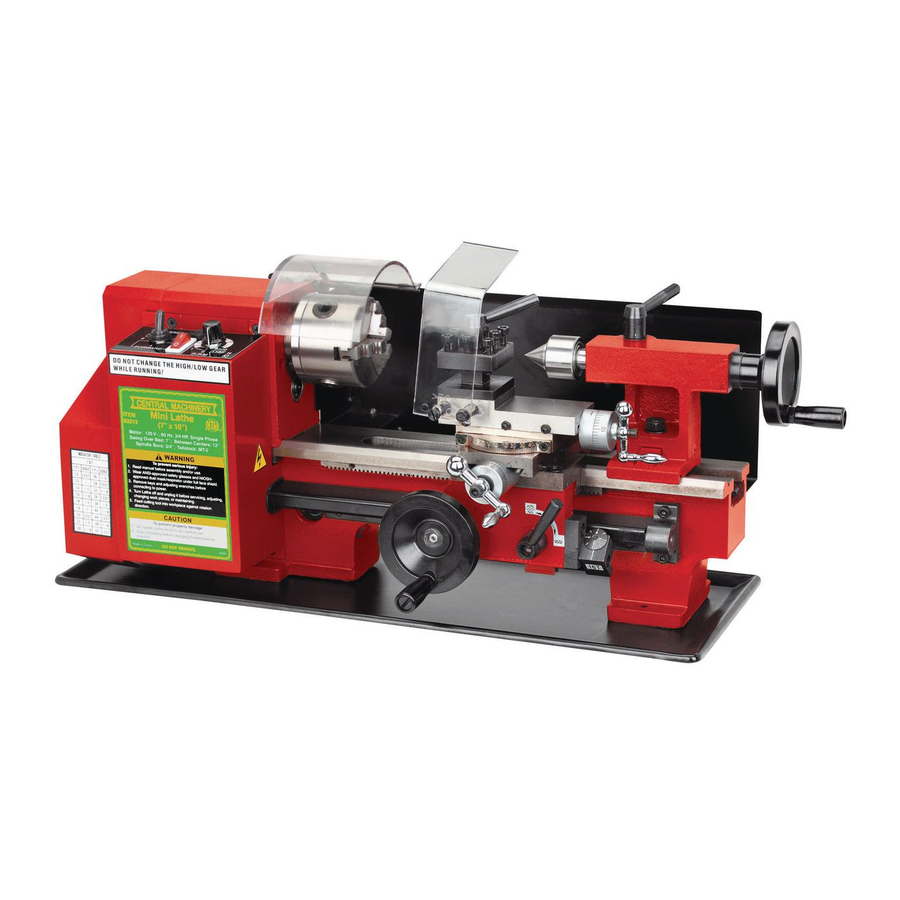
- 4 Identification of Main Components
- 5 Replacement of Chuck
- 6 Compound Rest Adjustment
- 7 Replacement of Jaws
- 8 Tool Post Adjustment
- 9 Automatic Feeding
- 10 Operation
- 11 Parts Diagram
- 12 Packing List
- 13 Schematic Diagram
- Download this manual
7" x 10" Mini Lathe
Model 33684
Assembly and Operating Instructions
®
3491 Mission Oaks Blvd., Camarillo, CA 93011
®
Copyright
2000 by Harbor Freight Tools
. All rights reserved. No portion of this
manual or any artwork contained herein may be reproduced in any shape or form
without the express written consent of Harbor Freight Tools.
For technical questions and replacement parts, please call 1-800-444-33534.
Advertisement
Table of Contents

Related Manuals for Central Machinery 33684


Summary of Contents for Central Machinery 33684
- Page 1 . All rights reserved. No portion of this manual or any artwork contained herein may be reproduced in any shape or form without the express written consent of Harbor Freight Tools. For technical questions and replacement parts, please call 1-800-444-33534.
-
Page 2: Important Safety Instructions
2. Do not attempt to use inappropriate attachments in an attempt to exceed the tool’s capacity. Approved accessories are available from Harbor Freight Tools. 3. Check for damaged parts. Before using any tool, any part that appears damaged should be carefully checked to determine that it will operate properly and perform its in- tended function. -
Page 3: Extension Cords
AWG rating. Every cord must meet the AWG rating. Use the chart below to determine what AWG rating is required for your situation. Cord length is rated in feet. Harbor Freight Tools can supply UL listed and outdoor rated extension cords in multiple AWG ratings if needed. -
Page 4: Technical Specifications
Never use instruments to measure the workpiece ____________________________________________________________________________ Thank you for choosing a Harbor Freight Tools product! For future reference, please complete the owner’s record below: Model:_______________ Serial Number:_________________ PurchaseDate:__________ SAVE THE RECEIPT, WARRANTY AND THESE INSTRUCTIONS. It is important that you read the entire manual to become familiar with the unit BEFORE you begin assembly. -
Page 5: Identification Of Main Components
Do not discard any packing material until the Mini Lathe is fully assembled and operational. If any parts are missing or broken, please call Harbor Freight Tools at 1-800-444-3353. Be sure you have all parts described in the parts listing on page . - Page 6 10.Tailstock Quill Fix Holder 11. Tailstock 12. Tailstock Quill Adjust Handwheel 13. Tailstock Set Screw 14. Compound Rest Crank SKU #33684 Mini Lathe Features 1.15. Feeding Control Wheel 16. Cross Feeding Crank 17. Automatic Feeding Handle 18. Thread Dial Indicator 19.
-
Page 7: Replacement Of Chuck
THIS SPEED CONTROL KNOB MUST BE AT ZERO. 6. Plug in the electrical cord and turn the Switch to the ON position and run the lathe for 3 minutes. When the lathe is on, the Power Lamp (#2) will remain on. Check to see that the lathe operates normally. -
Page 8: Compound Rest Adjustment
To replace, remove brush covers on the motor cover (A) in figure 10-A, and the right bottom side of speed controller as shown in (B) of figure 10-B. SKU #33684 If the jaws do not fit well together, you will need to reassemble them again. -
Page 9: Tool Post Adjustment
(figure 13 below). Then, use the rolling center to fix the other end. If you change the rolling center to drilling chuck you start your drilling immediately. SKU #33684 Threading Select the feeding direction selector to the thread direction desired. Then press down... - Page 10 4. After adjusting the angle of the compound rest, you can do bevel cutting (figure 16). Set-Up Instructions for Threading Gears By changing the gear set-up it is possible to cut any thread size. The factory set-up for Mini Lathe gears is as follows (see illustration below): To change the thread size, use the gear box settings shown on the table on the next page.
- Page 11 D, and put any other gear is position B to connect A and D. Example: To cut 38 threads per inch (see illustration above), use 20T in position A, 57T in position D, 50T in position B, and 60T in position C. SKU #33684 Threads Per Inch...
- Page 12 SKU #33684 Page 13...
- Page 13 SKU #33684 Page 14...
-
Page 14: Parts Diagram
Parts Diagram SKU #33684 Page 15... - Page 15 Additional Set-Up Instructions for Threading Gears When the lathe is ON and the Spindle is revolving, the threaded bar and the Thread Dial Indicator will also be revolving (see below). Indicator Housing Top View Thread Indicator Housing Move the cutting blade to the proper position, and adjust theThread Dial Indicator to the desired mark.
- Page 16 SKU #33684 Page 16...
-
Page 17: Packing List
Inside six horn wrench S: 3, 4, 5, 6 Oil can Center MT: 2 Rubber Knob Instruction Manual Wiring Diagram of Control Circuit Warranty Document SKU #33684 PACKING LIST 1 piece 3 piece 1 piece 1 piece 10 pieces 2 pieces... -
Page 18: Schematic Diagram
SCHEMATIC DIAGRAM Fuse Potentiometer Switch 2 Switch 1 Motor 110V/60Hz SKU #33684 REV 08/04 Page 18...