Table of Contents
Advertisement
Quick Links
Advertisement
Table of Contents

Related Manuals for Chauvet Intimidator Spot LED 250


Summary of Contents for Chauvet Intimidator Spot LED 250
- Page 1 User Manual...
-
Page 2: Table Of Contents
5. Technical Information ..............19 Product Maintenance ..................19 General Troubleshooting................. 20 Contact Procedure ..................21 CHAUVET® Contact Information ..............21 Returning Products to CHAUVET® ..............21 DMX Primer ..................... 22 Introduction ......................22 DMX Configuration ....................23 DMX Connectivity ..................... 23 6. -
Page 3: Before You Begin
CHAUVET®. Failure to do so in a timely manner may invalidate your claim with the carrier. In addition, keep the container and all the packing material for inspection. -
Page 4: Product At A Glance
Product at a Use on Dimmer Auto Programs Glance Outdoor Use Auto-ranging Power Supply Sound Activated Replaceable Fuse User Serviceable Master/Slave Duty Cycle Safety Notes Please read the following Safety Notes carefully before working with the product. The Notes include important safety information about installation, usage, and maintenance. -
Page 5: Introduction
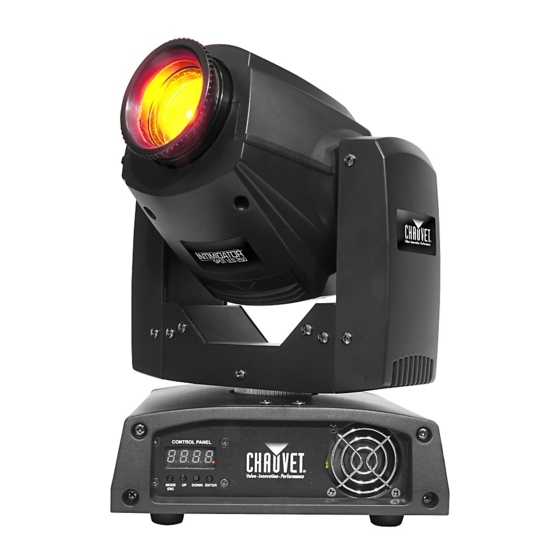
2. I NTRODUCTION Product Overview Control Panel and Cooling Fan Button Menu Power In DMX Out Power Out DMX In Fuse Holder Intimidator™ Spot LED 250 User Manual (Rev. 03) Page 5 of 26... -
Page 6: Product Dimensions
Product Dimensions Page 6 of 26 Intimidator™ Spot LED 250 User Manual (Rev. 03) -
Page 7: Setup
3. S ETUP AC Power The Intimidator™ Spot LED 250 has an auto-ranging power supply and it can work with an input voltage range of 100~240 VAC, 50/60 Hz. To determine the product’s power requirements (circuit breaker, power outlet, and wiring), use the current value listed on the label affixed to the product’s back panel, or refer to the product’s specifications chart. -
Page 8: Power Linking
The power linking diagram shown above corresponds to the North American version of the product ONLY! If using the product in other markets, you must consult with the local CHAUVET® distributor as power linking connectors and requirements may differ in your country or region. -
Page 9: Mounting
Mounting Before mounting the product, read and follow the safety recommendations indicated in the Safety Notes section (page 2 of this manual). Orientation The Intimidator™ Spot LED 250 may be mounted in any position; however, make sure adequate ventilation is provided around the product. Rigging ... -
Page 10: Operation
4. O PERATION Control Panel To access the control panel functions, use the four buttons located underneath the display. Please refer to the Product Overview to see the button locations on the control Operation panel. Button Function Press to find an operation mode or to back out of the current menu <MODE/ESC>... -
Page 11: Configuration (Dmx)
Configuration Set the product in DMX mode to control with a DMX controller. Connect the product to a suitable power outlet. (DMX) Turn the product on. Connect a DMX cable from the DMX output of the DMX controller to the DMX input socket on the product. -
Page 12: Dmx Channel Assignments And Values
DMX Channel Assignments and Values 13-CH Channel Function Value Setting 000 255 0-540° Fine Pan 000 255 Fine control of panning Tilt 000 255 0-270° Fine Tilt 000 255 Fine control of tilting Speed 000 255 Pan/Tilt speed (fast to slow) 000 ... - Page 13 Continued from previous page 000 063 Indexing 064 147 Rotation effect with increasing speed Gobo Rotation 148 231 Reverse rotation effect with increasing speed 232 255 Gobo bounce 000 015 Open Prism 016 255 Prism on Dimmer 000 ...
- Page 14 8-CH Channel Function Value Setting 000 255 0-540° Tilt 000 255 0-270° 000 006 White 007 013 Yellow 014 020 Pink 021 027 Green 028 034 Red 035 041 Light Blue 042 048 Kelly Green 049 ...
-
Page 15: Configuration (Standalone)
Configuration Set the product in one of the standalone modes to control without a DMX controller. Connect the product to a suitable power outlet. (Standalone) Turn the product on. Never connect a product that is operating in any standalone mode (either Static, Automatic, or Sound) to a DMX string connected to a DMX controller. -
Page 16: Manual Pan/Tilt Operation
Manual Pan/Tilt To select whether you want the Intimidator™ Spot LED 250 to operate with normal panning or inverted panning, do the following: Operation Press <MODE/ESC> repeatedly until PAn shows on the display. Press <UP> or <DOWN> to select normal pan operation (PAn) or inverse pan operation (r PAn). -
Page 17: Master/Slave Mode
Master/Slave The Master/Slave mode allows a single Intimidator™ Spot LED 250 unit (the “master”) to control the actions of one or more Intimidator™ Spot LED 250 units (the “slaves”) Mode without the need of a DMX controller. The master unit will be set to operate in either Automatic or Sound Active mode, while the slave units will be set to operate in Slave Mode. -
Page 18: Miscellaneous Operations
Miscellaneous Operations Reset Software To reset the software on the Intimidator™ Spot LED 250, do the following: Press <MODE/ESC> repeatedly until rESt shows on the display. Press <ENTER>. The product will reset all settings in the software to the default factory settings. -
Page 19: Technical Information
5. T ECHNICAL NFORMATION Product Dust build up reduces light output performance and can cause overheating. This can lead to reduction of the light source’s life. To maintain optimum performance and Maintenance minimize wear, you should clean your lighting products at least twice a month. However, be aware that usage and environmental conditions could be contributing factors to increase the cleaning frequency. -
Page 20: General Troubleshooting
Terminator not connected Install a terminator, as indicated in the DMX Primer section. If you still experience problems after trying the above solutions, contact CHAUVET® Technical Support. Page 20 of 26 Intimidator™ Spot LED 250 User Manual (Rev. 03) -
Page 21: Contact Procedure
If you live in the UK or Ireland, contact CHAUVET® Europe Ltd.(see below). If you live in any other country, DO NOT contact CHAUVET®. Instead, contact your distributor of record. Refer to our Web site for contact details of distributors outside the US, United Kingdom, or Ireland. -
Page 22: Dmx Primer
DMX Primer Introduction The DMX protocol (USITT DMX512-A) is a networking protocol that enables a universal DMX controller device to control the features of multiple DMX compatible fixtures, whether PAR cans, wash lights, moving heads, followspots, foggers, or proprietary fixture controllers, etc. As any other networking protocol, the USITT DMX512-A describes the physical medium, the signals, and the functions they control. -
Page 23: Dmx Configuration
DMX Configuration The DMX fixture configuration consists in determining how many channels each fixture will need as well as assigning the corresponding DMX channels to each fixture in order to size correctly the DMX controller. A DMX personality describes what channel or channels control which fixture Personalities parameters. - Page 24 You must use DMX compliant data cables to link two or more DMX compatible DMX Data Cabling fixtures. You may purchase CHAUVET® certified DMX cables directly from a dealer/distributor or construct your own cable. USITT recommends limiting the total length of the DMX cable (from the first fixture/controller to the last fixture) to 300~455 m (985~1,500 ft).
- Page 25 (DMX Connectivity cont.) Test all DMX cables with an ohmmeter to verify their correct polarity and to make sure that there are no short-circuits between any of the pins, or between any pin and ground. If the common wire (shield) touches the chassis ground, a ground loop could form, which may cause the fixture to perform erratically.
-
Page 26: Technical Specifications
6. T ECHNICAL PECIFICATIONS Length Width Height Weight Dimensions and 9.3 in (236 mm) 8.1 in (205 mm) 11.3 in (287 mm) 12.6 lbs (5.7 kg) Weight Note: Dimensions in inches rounded to the nearest decimal digit. Power Supply Type Range Voltage Selection Power...