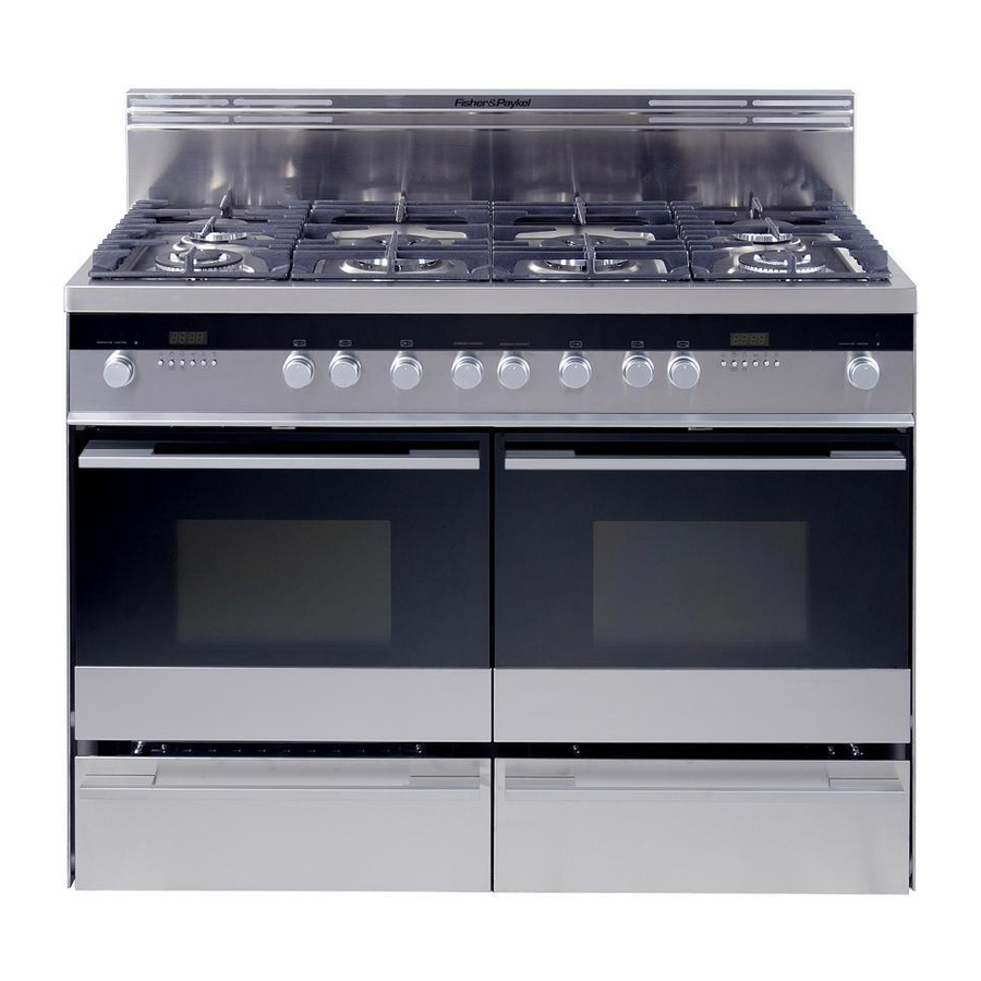
Fisher & Paykel OR48DDPWGX Installation Instructions Manual
Hide thumbs
Also See for OR48DDPWGX:
- User manual (72 pages) ,
- Installation instructions manual (48 pages) ,
- User manual (70 pages)
Table of Contents
Advertisement
Available languages
Available languages
Quick Links
Download this manual
See also:
User Manual
Advertisement
Table of Contents

Related Manuals for Fisher & Paykel OR48DDPWGX


Summary of Contents for Fisher & Paykel OR48DDPWGX
- Page 1 Freestanding _ange Instructions d'installation OR48DDPWGX model...
- Page 2 WARNING ,, ALL RANGES CAN TiP ,, iNJURY TO PERSON COULD RESULT ,, iNSTALL ANTI=TIP DEVICE PACKED WiTH RANGE ,, SEE iNSTALLATiON iNSTRUCTiONS WARNING" IF THE INFORMATION IN THIS MANUAL IS NOT FOLLOWED EXACTLY, A FIRE OR EXPLOSION RESULT CAUSING PROPERTY DAMAGE, PERSONAL...
- Page 3 DATA PLATE CONVERSION LABEL IMPORTANT - PLEASE READ AND FOLLOW ¢" Before beginning, please read these instructions completely carefully. ¢" Do not remove permanently affixed labels, warnings, or plates from the product. This may void the warranty. ¢" Please observe all local and national codes and ordinances.
-
Page 4: For Installation
WARNING! THIS APPLIANCE HAS TO BE INSTALLED BY A QUALIFIED INSTALLER. Improper installation, adjustment, alteration, services, or maintenance can cause injury or property damage. Consult a qualified installer, service agent, or the gas supplier. TOOLS NEEDED FOR INSTALLATION T-handle Adjustable Screwdriver Wrench wrench... -
Page 5: General Information
GENERAL INFORMATION WARNING!! 1. Installation must conform with local codes or, in the absence of local codes, with the National Fuel Gas Code, ANSI Z223.1-Latest Edition, CAN/CGA-B149.1 or CAN/CGA- ELECTRICAL GROUNDING INSTRUCTIONS B149.2. The range must be electrically grounded in accordance with local codes... -
Page 6: Installation
installation PROXIMITY TO SIDE CABINETS The range CANNOT be installed directly adjacent to side- 1. This range may be installed directly adjacent to existing 36" walls, tall cabinets, tall appliances, or other side vertical (914 mm) high base cabinets. surfaces above 36" (914 mm) high. Range dimensions: There must be a minimum of 11"... - Page 7 i_ _i 'i GAS AND ELECTRIC CONNECTION Rif. inch 15" 3/4 2" 51/64 21/32" 16.5 4" 7/32 - 4" 11/16 (*) 107 - 119 (*) * : Depending on feet regulation Area for GAS and ELECTRIC connection Dotted line showing the position of the range when installed Fig.
- Page 8 PROXIMITY TO SIDE CABINETS RANGE WITH BACKGUARD ram) Fig. 1.3b...
- Page 9 13"max,(330 PROXIMITY TO SIDE CABINETS RANGE WITH ISLAND TRIM Fig. 1.3c Fig. 1.3d...
- Page 10 ASSEMBLING THE BACKGUARD OR THE ISLAND TRIM It is mandatory to install the backguard or the island trim • Assemble the backguard or the island trim as shown in figure 1.4 or 1.5 and fix it by screwing the 5 screws "A". i!iiiii!i Fig.
- Page 11 (,i ) LEVELLING THE RANGE The range is equipped with 6 LEVELLING FEET (already fitted on the appliance) and may be levelled by screwing or unscrewing the feet (fig. 1.9). It is important to observe the prescriptions of figures 1.6, 1.7, 1.8. &...
- Page 12 L i_ ,i _ ANTI-TIP STABILITY DEVICE INSTALLATION INSTRUCTIONS YOU MUST USE STABILITY ANTI BRACKET 1. The anti-tip bracket has to be attached as shown on figure below (only rear cental PREVENT UNIT FROM position), it has to be fixed on the floor and on the rear wall by no. 4 (four) suitable TIPPING.
-
Page 13: Gas Connection
connection All gas connections must be made according to national and local codes. This gas supply (service) line must be the same size or greater than the inlet line of the WARNING appliance. Sealant on all pipe joints must be resistant to te action of LP/Propane gas. -
Page 14: Pressure Regulator
PRESSURE REGULATOR INSTALLATION STEP 1 Mount the 1/2" NPT (conical) male connector to the pressure regulator and tighten by using a wrench. LOCK Do not over tighten the connector. Over tightening may crack regulator. Fig. 2.2a STEP 2 Assemble the 1/2" NPT connector + pressure regulator group to the extension pipe interposing the gasket supplied. -
Page 15: Specification
GAS CONNECTION SPECIFICATION Manifold malepipe fittin_ (ISO 228-I) male I/2" G cylindrical I/2" G cylindrical (ISO 228-I) female To range Extension / pipej I/2" G cylindrical pipe male (ISO 228-I) male pipe fitting I/2" G cylindrical (ISO 228-I) female To mains male connection 1/2"... - Page 16 b) Any conversion required must be performed by your dealer or a qualified licensed plumber or gas service company. Please provide the service person with this manual before work is started on the range. (Gas conversions are the responsibility of the dealer or end user.) c) This range can be used with NATURAL or LP/PROPANE gas.
-
Page 17: Setting The Pressure
CONVERSION TO LP/PROPANE Every range is provided with a set of injectors for the various types of gas. Select the injectors to be replaced according to the "INJECTORS TABLE". The nozzle diameters, expressed in hundredths of a millimetre, are marked on the body of each injector. - Page 18 _f _='_,% To set the pressure regulator (fig. 2.8): 1. Unscrew the regulator cover; 2. Unscrew the A component, reverse and screw it according to the LP/PROPANE regulation. I Pressure regulator REGULATOR COVER Fig. 2.8 NATURAL GAS LP/PROPANE REGULATION REGULATION Fitting the warming drawer...
- Page 19 ..... INJECTORS TABLE RBURNE S .OMINALPOWER REDUCEDPOWER 11 W.C.R 4 W.O.R BTU/hr BTU!hr O injector By-pass £_injector By:Pass [1/100 ram] [1/100 mm] [1/100 [1/100 ram] Rapid (R} 10000 2000 adjustable Triple ring (TC) 12000 5000 adjustable Inner crown 2800 forNATURAL GAS (_) 1000 (*) adjustable 3500...
- Page 20 SETTING THE BURNER MINIMUM When switching from one type of gas to another, the minimum flow rate must also be correct: the flame should not go out even when passing suddenly from maximum to minimum flame. To regulate the flame follow the instructions below: Rapid and triple ring burners...
- Page 21 electrical connection If codes permit and a separate ground wire is used, it is recommended that a qualified electrician installer determine that the ground path and wire gauge are in accordance with local codes. Be sure that the electrical connection and wire size are adequate and in conformance with: - ANSl/NFPA 70 latest edition and local codes and ordinances - CSA Standard C22.1, Canadian Electrical Code, Part 1 - latest edition, and all local...
- Page 22 ...d...
- Page 24 AVERTISSENIENT ,, TOUS LES TYPES DE CUISINli_RE PEUVENT BASCULER ,, CELA PEUT PROVOQUER DES BLESSURES ,, INSTALLEZ LE DISPOSITIF ANTIBASCULEMENT FOURNI AVEC LA CUISINli_RE e CONSULTEZ LES iNSTRUCTiONS D'INSTALLATION AVIERTISSlEMIENT : SI L'INFORMATION CONTENUE DANS MANUEL N'EST PAS SUIVIE A LA LETTRE, UN INCENDIE UNE EXPLOSION PEUVENT...
- Page 25 PLAQUE SIGNALFtTIQUE FtTIQUETTE DE CONVERSION IMPORTANT - VEUILLEZ LIRE ET SUIVRE v" Avant de commencer, veuillez lire attentivement toutes les instructions. N'enlevez pas les etiquettes, plaques ou avertissements permanents I'appareil. Cela pourrait annuler la garantie. ,/ Veuillez respecter tousles codes et les r_glements Iocaux et nationaux.
-
Page 26: Outils Requis Pour L'installation
AVERTISSEMENT! CET APPAREIL DOlT ETRE INSTALLI_ PAR UN INSTALLATEUR QUALIFII_, Une mauvaise installation, modification, r_paration ou un mauvais reglage ou entretien peuvent causer des blessures ou des dommages materiels, Consultez un installateur qualifi_, un agent autoris_ ou le foumisseur de gaz, OUTILS REQUIS POUR L'INSTALLATION... - Page 27 RENSEIGNEMENTS GC:NC:RAUX 1. L'installation dolt 6tre conforme aux codes Iocaux ou, en AVERTISSEMENT!! I'absence de ceux-ci, & la derniere edition du National Fuel Gas Code, ANSI Z223.1, au CAN/CGA-B149.1 ou au CAN/ INSTRUCTIONS DE MISE A LA TERRE CGA-B149.2. La cuisini_re dolt _tre mise a la terre conformement 2.
- Page 28 installation PROXIMITI_ DES ARMOIRES La cuisiniere NE PEUT PAS _tre installee directement 1. Cette cuisiniere peut _tre installee directement adjacente adjacente a un mur, a une armoire haute, a un electromenager des armoires de base existantes de 36 po (914 mm) de hauteur.
- Page 29 i_ _i 'i RACCORDEMENTS I_LECTRIQUE ET AU GAZ Ref. pouces 15-3/4 po 2-51/64 po 21/32 po 16,5 4-7/32 po - 4-11/16 po (') 107-119(*) * : En fonction du reglage des pieds Zone pour le raccordement au GAZ _ Ligne pointillee illustrant la posi- et le raccordement I_LECTRIQUE _ tion de la cuisiniere au moment...
- Page 30 PROXIMITE DES ARMOIRES CUlSINIERE AVEC DOSSERET 11.13/16 (or_r_)
- Page 31 PROXIMITE DES ARMOIRES 13po(330ram)ma. CUlSINIERE AVEC GARNITURE D'|LOT 1lq3/_6 Fig. 1.3c 13po 330ram)max,. 11"13/t6 Fig. 1.3d...
- Page 32 i_"_i .ili MONTAGE DU DOSSERET DE LA GARNITURE D'|LOT L'installation du dosseret ou de la garniture d'ilot est recomman- d_e. • Montez le dosseret ou la garniture d'flot tel qu'indique & la figure 1.4 ou 1.5 et fixez-le en vissant les 5 vis << A >_. Fig.
- Page 33 //¸*¸¸¸¸¸¸-¸¸%¸¸ (,i ) MISE A NIVEAU DE LA CUISINIERE La cuisiniere est munie de 6 PIEDS DE MISE/_, NIVEAU (deja installes sur la cuisiniere) et peut _tre mise a niveau en vissant ou en devissant ces pieds (fig. 1.9). II est important de respecter les instructions des figures 1.6, 1.7, 1.8.
- Page 34 INSTRUCTIONS D'INSTALLATION DU DISPOSITIF VOUS DEVEZ UTILISER LE STABILITI_ ANTIBASCULEMENT SUPPORT DE STABILITrt ANTIBASCULEMENT POUR 1. Le support antibasculement doit _tre fixe tel qu'indique dans I'illustration ci-dessous I_VITER QUE L'APPAREIL (seulement le c6te arriere, au centre). Vous devez le fixer au sol et au mur arriere avec BASCULE.
-
Page 35: Risque D'explosion
raccordement Tousles raccordements au gaz doivent _tre effectues conformement aux codes natio- naux et Iocaux. Ce tuyau d'alimentation en gaz dolt 6tre du m_me format ou plus grand que la conduite de I'appareil. Le produit d'etancheite sur tousles joints de tuyau dolt AVERTISSEMENT 6tre resistant a Faction du gaz propane/GPh Cet appareil est muni d'un equipement... - Page 36 INSTALLATION DU RI_GULATEUR DE PRESSION ETAPE 1 Montez le connecteur m&le (conique) NPT de 1/2 po sur le regulateur de pression et serrez avec une clef. FERMER Ne serrez pas le connecteur outre mesure. Trop serrer pourrait entrainer une fissure dans le regulateur. Fig.
- Page 37 SPleCIFICATION DU RACCORDEMENT AU GAZ o,,oo,eo 0e ,you a u 0 !! cteu Mfle G cylindrique (ISO 228-I) de I/2po Femelle G cylindrique (ISO 228-I) de I/2 po Vers la cuisiniere IRa0co fome; dutuyaude prolongation/ prolongation du tuyau de M&le G cylindrique (ISO 228-I) de I/2 po -O/'n_...
- Page 38 b) Toute conversion requise doit _tre effectuee soit par votre detaillant, soit un techni- cien qualifie ou par la societe gaziere. Veuillez remettre le present manuel au techni- cien avant de commencer I'entretien de la cuisiniere. (Les conversions de gaz sont la responsabilite du detaillant ou de I'utilisateur final.) c) Cette cuisiniere fonctionne...
- Page 39 CONVERSION AU GAZ PROPANE/GPL Chaque cuisiniere est fournie avec un ensemble d'injecteurs pour les divers types de gaz. Choisissez les injecteurs a _tre remplaces selon le ,, TABLEAU DES INJECTEURS _. Le diametre de la busette, exprime en centiemes de millimetre, est indique sur le corps de chaque injecteur.
- Page 40 /_=,_ Pour r_gler le r_gulateur de pression (fig. 2.8) : 1. Devissez le couvercle du regulateur. 2. Devissez le composant A, inversez-le et vissezde selon le reglage PROPANE/GPL. Regulateur de pression COUVERCLE DU REGULATEUR Fig. 2.8 REGLAGE REGLAGE GAZ NATUREL PROPANE/GPL Installation du tiroir de maintien...
- Page 41 ..... TABLEAU DES INJECTEURS PROPANEIGPL GAZ NATUREL PUISSANCE NOMINALE PUISSANCE RF:DUITE Pressionde 11 poCE Pression de 4 po CE BRULEURS BTU/h BTU!h Injecteur O Derivation Injecteur O D_rivati0n [1/100ram] [1/100mm] [1/100mm] [1/100 ram] Rapide (R) 10-000 2-000 reglable Triple couronne (TC) 12-000 5-000 reglable...
- Page 42 RC:GLAGE MINIMUM DU BRULEUR Lorsque vous passez d'un type de gaz a un autre, le debit minimal doit aussi _tre correct : les flammes ne devraient pas s'eteindre m_me Iors du passage brusque des flammes maximales aux flammes minimales. Pour regler les flammes, suivez les instructions ci-dessous Br_leurs rapide...
- Page 43 raccordement lectrique Si les codes le permettent et qu'un fil de mise a la terre distinct est utilis_, il est recommand_ qu'un _lectricien qualifi_ d_termine que le trajet de mise a la terre et le calibre du fil sont conformes aux codes Iocaux. Assurez-vous que le raccordement electrique et que la taille du fil sent adequats et...
- Page 44 <€ ,,-I ,<€ (,.) ,iii "1" (,.) IB II...
- Page 45 Copyright _ Fisher & Paykel 2007. All rights reserved. The oroauc_ soecifications - this DOOKle_apply _o _ne st_ecific aroauc_s a ]a models described at _ne aa_e Df issue, u naer our policy of contiP Jous oroauc_ _-orovemenL _nese soecifications may change a_ any time.