
Related Manuals for Hach 900 MAX


Summary of Contents for Hach 900 MAX
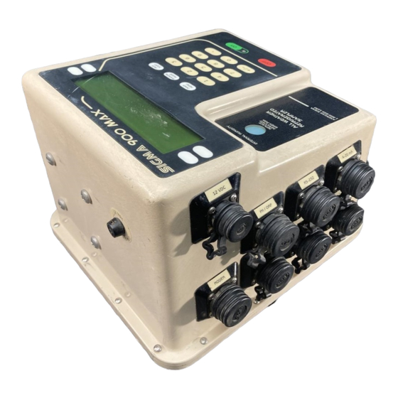
- Page 1 Catalog Number 8990 Sigma 900 MAX Refrigerated Sampler INSTRUMENT MANUAL 07/03 4ed...
- Page 3 Catalog Number 8990 Sigma 900 MAX Refrigerated Sampler INSTRUMENT MANUAL © Hach Company, 2002, 2003. All rights reserved. Printed in the U.S.A. eac 07/03 4ed...
- Page 4 Visit http: //www.hach.com...
-
Page 5: Table Of Contents
Safety Precautions ... 7 Specifications ... 9 Section 1 Introduction ... 15 1.1 Controller Cover ... 15 1.2 Front Panel... 15 1.2.1 Keypad Description... 16 1.2.2 Liquid Crystal Display ... 16 1.2.3 Internal Humidity Indicator... 17 1.3 Interface Connectors... 18 1.3.1 Receptacle Caps ... - Page 6 Table of Contents 4.1.3 Downlook Ultrasonic Sensor Calibration ... 61 4.1.3.1 Liquid Depth... 61 4.1.3.2 Sensor Height ... 62 4.1.3.3 Setting the Invisible Range ... 62 4.2 Submerged Area/Velocity Sensor ... 63 4.2.1 Submerged Area/Velocity Sensor Connection... 63 4.2.2 Submerged Area/Velocity Sensor Programming ... 63 4.2.3 Submerged Area/Velocity Submerged Area/Velocity Sensor Calibration ...
- Page 7 Sigma 900 MAX Refrigerated Sampler Advanced Sampling Flow Chart ... 108 Sigma 900 MAX Refrigerated Sampler Alarms Flow Chart... 109 Sigma 900 MAX Refrigerated Sampler Calibration Flow Chart (1 of 2) ... 110 Sigma 900 MAX Refrigerated Sampler Calibration Flow Chart (2 of 2) ... 111 Appendix B Programming Features ...
- Page 8 Appendix E Exploded Drawings ... 137 Sigma 900 MAX Refrigerated Sampler Assembly Drawing (1 of 3) ... 137 Sigma 900 MAX Refrigerated Sampler Assembly Drawing (2 of 3) ... 138 Sigma 900 MAX Refrigerated Sampler Assembly Drawing (3 of 3) ... 139 Sigma 900 MAX Refrigerated Composite Sampler Assembly...
-
Page 9: Safety Precautions
Please read this entire manual before unpacking, setting up, or operating this instrument. Pay particular attention to all danger and caution statements. Failure to do so could result in serious injury to the operator or damage to the equipment. To ensure the protection provided by this equipment is not impaired, do not use or install this equipment in any manner other than that which is specified in this manual. - Page 10 Definition of Confined Space Page 8 Safety Precautions The Sigma 900 MAX Refrigerated Sampler is not approved for use in hazardous locations as defined in the National Electrical Code. DANGER Bien que certains produits Sigma soient conçus et certifiés pour être installés dans des endroits dangereux tels que définis par le National Electric Code, de...
-
Page 11: Specifications
General Dimensions Width 61 cm (24 in.), Depth 61 cm (24 in.), Height 110 cm (43.5 in.), Weight 63.3 kg (140 lb) Cabinet Fiberglass reinforced plastic with beige UV inhibited polymer laminate. -29 to +50 °C (-20 to 122 °F); With optional controller compartment heater, -40 to +50 °C Temperature Range (-40 to 122 °F). - Page 12 Specifications Sample Bottle Capacity Single Bottle Mode 6 gal polyethylene (with polypropylene cap) Two Bottle Sampling: Set of two 2.5 gal glass (with Teflon 3 gal polyethylene bottle (with polypropylene cap) Four Bottle Sampling: Set of four 2.5 gal glass (with Teflon-lined lid) or 3 gal polyethylene bottles (with polypropylene cap) Multiple Bottle Mode Eight Bottle Sampling: Set of eight 1.9 liter glass bottles (with Teflon-lined lid) or...
- Page 13 Air purged automatically before and after each sample; duration automatically compensates Intake Purge for varying intake line lengths. Pump/Controller High impact injection molded ABS; submersible, watertight, dust tight, corrosion & ice Housing resistant; NEMA 4X,6. Internal Clock Indicates real time and date; 0.007% time base accuracy. Manual Sample Initiates a sample collection independent of program in progress.
- Page 14 Specifications Rain Gauge Input For use with the Tipping Bucket Rain Gauge. The Sampler Program can be initiated upon field selectable rate of rain. General Information Sampler records rainfall data. Each tip = 0.25 mm (0.01in.) of rain. Analog Input Channels Up to 3 additional data logging channels record data from external source(s) General Information Field assignable units...
- Page 15 Submerged Area/Velocity Probe Method Doppler Principle/Pressure Transducer. Material Polymer body, 316 series stainless steel diaphragm. Cable 8-conductor urethane sensor cable with air vent. Cable Length 7.6 m (25 ft) standard Length: 12.7 cm (5 in.) Sensor Dimension Width: 3.8 cm (1.5 in.) Height: 2 cm (0.8 in.) Velocity accuracy: 2% of reading;...
- Page 16 Visit http: //www.hach.com...
-
Page 17: Section 1 Introduction
Section 1 1.1 Controller Cover 1.2 Front Panel Figure 1 Front Panel Soft Keys Manual Mode Key Run/Stop Key Power ON Key 8990int.fm Introduction The controller is mounted on top of a specially designed refrigerator. The sample line passes through the top of the refrigerator and into the refrigerated compartment where the sample containter(s) are located. -
Page 18: Keypad Description
Section 1 1.2.1 Keypad Description Function Key Main Menu This is the starting point to get to any other point in the program. Press the Main Menu key at any time during programming to return to the Main Menu Screen. The current action is cancelled if changes are not yet accepted. -
Page 19: Internal Humidity Indicator
1.2.3 Internal Humidity Indicator Figure 2 Humidity Indicator 8990int.fm Status Bar The Status Bar appears along the bottom edge of the display. The appearance of the status bar changes depending upon the function performed (Figure 1). The lower left corner of the Status Bar indicates whether a program is Complete, Running, Halted, or Ready To Start. -
Page 20: Interface Connectors
Section 1 1.3 Interface Connectors 12 V dc 1.3.1 Receptacle Caps Page 18 Interface Connectors Interface connectors are located on the left side of the controller housing. An optional weather tight terminal box located on the back of the sampler provides conduit termination for all input/output lines. -
Page 21: Principle Of Operation
1.4 Principle of Operation 1.4.1 Liquid Sensing Figure 3 Liquid Sensor Sensor Body 8990int.fm The sampler is designed for indoor, permanent installation. All controls are located on the front panel. Capped, watertight connectors for interfacing to external devices are located along the left side of the controller. The sampler uses a liquid sensing system to detect the absence or presence of liquid at the peristaltic pump intake. - Page 22 Section 1 Page 20 Principle of Operation Intake Tube Pre-Rinse The liquid sensor also rinses the intake tubing with the liquid from the sample source before taking each sample. Upon sample initiation, the pump purges the intake line. The pump then reverses, pulling liquid through the tubing, until it reaches the liquid sensor.
-
Page 23: Installation
Some of the following manual sections contain information in the form of warnings, cautions and notes that require special attention. Read and follow these instructions carefully to avoid personal injury and damage to the instrument. Only personnel qualified to do so, should conduct the installation/maintenance tasks described in this portion of the manual. - Page 24 Visit http: //www.hach.com...
-
Page 25: Unpacking The Instrument
Cet appareil doit être installé par du personnel technique qualifié, afin d'assurer le respect de toutes les normes applicables d'électricité. Remove the sampler from the shipping carton and inspect it for any damage. Contact Hach Customer Service at 1-800-227-4224 if any items are missing or damaged. DANGER Ce produit n'est pas conçu pour des endroits dangereux dans lesquels il peut... -
Page 26: Installing The Pump Tube In The Sensor Body
Section 2 2.3 Installing the Pump Tube in the Sensor Body Note: Do not stretch the tubing in the sensor body, as this could affect the ability of the sensor to detect liquid through the pump tubing. Note: Use the proper length of silicone tubing in the pump body. -
Page 27: Attaching The Intake Line
2.3.1 Attaching the Intake Line 2.3.1.1 Attaching the Vinyl Tubing Figure 7 3/8” Vinyl Tubing Connector Vinyl tubing to controller Vinyl tubing to strainer or pump. ® 2.3.1.2 Attaching the Teflon -Lined Tubing 8990hrd.fm The connection kit (Cat. No. 2248) contains two identical assemblies, one for connecting vinyl tubing to the tubing attached to the sampler, and the other for connecting the vinyl tubing to an intake strainer or remote pump. -
Page 28: Setting Up The Intake Line And Strainer
The constituents of interest must be considered when positioning the intake strainer. A broad range of bottle configurations are available for the Sigma 900 MAX Refrigerated Sampler. 8990hrd.fm... -
Page 29: Setting Up The Bottles
Figure 9 Bottle Configurations 2.5 Setting Up the Bottles 2.5.1 One-Bottle Sampling 2.5.2 Two- and Four-bottle Sampling 8990hrd.fm For single bottle composite sampling, install the Full Bottle Shut-off (refer to Section 2.7 on page 31) and place the bottle in the center of the refrigerator (Figure 15 on page 31). -
Page 30: Eight-, 12-, Or 24-Bottle Sampling
Section 2 Figure 10 Two-bottle Locations Single Bottle Location Figure 11 Four-bottle Locations 1, 2, or 4 Bottle Locations 2.5.3 Eight-, 12-, or 24-bottle Sampling Page 28 Setting Up the Bottles For four-bottle sampling, install the distributor and place all four bottles in the tray as shown in Figure Front... -
Page 31: Installing The Distributor (Multiple Bottle Operation)
Figure 12 Eight-, 12-, or 24-bottle Configuration Distributor 2.6 Installing the Distributor (Multiple Bottle Operation) Note: Make sure the sampler is powered off before removing or installing the distributor. 8990hrd.fm Retainer For multiple bottle sampling, a motorized arm (Distributor) is provided to automatically position the sample tube over the proper bottle. -
Page 32: Distributor Arm Alignment
Section 2 2.6.1 Distributor Arm Alignment Figure 13 Distributor Tubing in Arm Distributor Shaft Figure 14 Distributor Installation Refrigerator Page 30 Installing the Distributor (Multiple Bottle Operation) 1. Program the sampler for 24-bottle operation. 2. Press to set the distributor shaft to the START PROGRAM Bottle #1 position. -
Page 33: Installing The Full-Bottle Shut-Off Device (Single Bottle Operation)
2.7 Installing the Full-Bottle Shut-Off Device (Single Bottle Operation) Figure 15 Full Bottle Shut-off Installation Full Bottle Shut-off 2.8 Power Connections Note: Install the sampler on its own circuit to ensure a continuous, stable source of power. 8990hrd.fm 1. Install the rubber grommet into the hole provided in the cap of the composite bottle. -
Page 34: Auxiliary Receptacle Pin Identification
Section 2 2.9 Auxiliary Receptacle Pin Identification Pin A/White (12 V dc) Powers an external device or flow meter. Must be used in conjunction with Pin B (ground). Pin B/Blue (Ground) Connected to dc ground and is isolated from the earth ground found in the ac power line. With the sampler in Flow Proportional mode and connected to an external flow meter, a 5 to 12 V dc input pulse lasting at least 25 milliseconds will cause the sampler to decrement one count. -
Page 35: Splitter Interface
2.9.1 Splitter Interface Figure 16 Splitter Interface 8990hrd.fm Use the Splitter Interface (Cat. No. 939) when more than one signal is needed simultaneously. Connecting the interface to the 6-pin connector on the sampler provides three additional connectors. Two or more interfaces may be connected in series to allow for additional connections. - Page 36 Visit http: //www.hach.com...
-
Page 37: Operation
Handling chemical samples, standards, and reagents can be dangerous. Review the necessary Material Safety Data Sheets and become familiar with all safety procedures before handling any chemicals. La manipulation des échantillons chimiques, étalons et réactifs peut être dangereuse. Lire les Fiches de Données de Sécurité... - Page 38 Visit http: //www.hach.com...
-
Page 39: Section 3 Basic Programming Setup
Section 3 3.1 Initial Power-Up of Sampler 3.2 Basic Programming Setup 8990startup.fm Basic Programming Setup After pressing the ON key, the sampler performs a complete diagnostic test and displays the menu shown when the unit was last turned off. Set the instrument programming features when the Main Menu is displayed. - Page 40 Section 3 Step 1 - Bottles Page 38 Basic Programming Setup To make changes to the program entries after the basic programming setup, press and select MAIN MENU SETUP>MODIFY SELECTED ITEMS the program entry using the To review all information in the Setup and Option menus without worrying about accidentally changing the information, use the Review All Items function to verify that the program is properly set up.
- Page 41 Step 2 - Intake Tubing Step 3 - Program Lock Note: The program lock password is configured at the factory as “9000” and cannot be changed. 8990startup.fm 1-C. Enter the bottle volume using the numeric keypad and select gallons or milliliters using the CHANGE UNITS 11:00 AM 21 - APR - 01...
- Page 42 Section 3 Step 4 - Program Delay Note: If both Setpoint Sampling and Program Delay are enabled, the program delay is evaluated first, prior to any checking for setpoint conditions. Step 5 - Sample Collection Timed-Proportional Sampling Intervals Page 40 Basic Programming Setup 4-A.
- Page 43 Flow Proportional Constant Volume, Variable Time (CVVT) 8990startup.fm b. Enter the Interval Between Samples. Press 11:00 AM 21 - APR - 01 ACCEPT INTERVAL: 00:00 (hrs:min) CANCEL ENTER: 000:01—999.00 (hrs:min) c. Select either Take First Sample Immediately or After The First Interval? Note: When the program is started, the first sample is taken immediately upon pressing the start button or after the first interval has elapsed.
- Page 44 Section 3 Page 42 Basic Programming Setup c. Select either Integral or External flow meter and press d. Enter the flow volume between samples using the numeric keypad and select a unit of measure using the . Refer to Table 2 for flow unit choices.
- Page 45 Flow Proportional Constant Time, Variable Volume Sampling (CTVV) 8990startup.fm A Level-Velocity Sensor Input must be logged and electrically connected for the CTVV feature to work correctly. CTVV samples are taken at user-specified constant (fixed) intervals. However the actual volume of each sampling is based on the known average flow rate of the site, the actual metered flow rate for each specific interval, the total sample volume desired, the user-specified collection period, and the specified Sampling Interval.
- Page 46 Section 3 Page 44 Basic Programming Setup a. In the Sample Collection menu, press Proportional is displayed. Press 11:00 AM 21 - APR - 01 ACCEPT SAMPLE COLLECTION: FLOW-PROPORTIONAL CANCEL ENTER: 1.00 - 99999999 b. In the Flow Pacing menu, press Const Time/Var Vol appears.
- Page 47 Step 6 - Sample Distribution 8990startup.fm In the Collection Period menu use the numeric keypad to enter the time period for collecting samples. 11:00 AM 21 - APR - 01 ACCEPT COLLECTION PERIOD 0:30 (hrs:min) CANCEL ENTER: 000:01—999:00 (hrs: min) g.
- Page 48 Section 3 Note: A high pressure air purge is automatically applied to the intake tube between each sample intake cycle. Page 46 Basic Programming Setup is selected: a. Select Samples per Bottle or Bottles per Sample. Example 1: Samples Per Bottle •...
- Page 49 Step 7 - Liquid Sensor Note: Sample retries cannot be enabled when the liquid sensor is disabled. 8990startup.fm b. If Stop After Last Sample is chosen, enter the samples to collect using the numeric keypad. Press Liquid Sensor. 11:00 AM 21 - APR - 01 ACCEPT SAMPLES TO COLLECT: BACKUP...
- Page 50 Section 3 Step 8 - Sample Volume Note: The minimum sample volume is ten milliliters. Step 9 - Intake Rinses Step 10 - Sample Retries Note: Excessive intake tube line lengths combined with multiple Intake Rinses and Sample Retries can increase the pump tube and drive train wear.
-
Page 51: Advanced Sampling
Step 11 - Site ID 3.3 Advanced Sampling 8990startup.fm 11-A. Enter a site identification number of up to 8 digits. This Site ID will appear on all data printouts. This feature is useful when multiple sites are monitored using a single flow meter or if data readings from multiple flow meters are collected. - Page 52 Section 3 Step 12 - Program Complete Output Step 13 - Setpoint Sampling Page 50 Advanced Sampling Program Complete Output sends a +12 V dc signal out Pin F of the Auxiliary Receptacle at the completion of the sampling program. This signal is also sent when a Full Bottle condition causes the program to complete.
- Page 53 8990startup.fm 13-C. Select either Start on Setpoint or Stop on Setpoint by pressing . Press CHANGE CHOICE ACCEPT • Start on Setpoint will start a program when the setpoint condition is met. The program continues to run even if the condition falls back within the setpoint limits.
- Page 54 Section 3 Channel Sampling Trigger Level Flow Flow Rate of Change pH or ORP Process Temperature Rainfall Analog Input Channel 1 Analog Input Channel 2 Analog Input Channel 3 Analog Input Channel 4 or DO Analog Input Channel 5 or DO Temperature Analog Input Channel 6 or Conductivity Analog Input Channel 7 or Conductivity Temperature External Control...
- Page 55 Step 15 - Start/Stop Times 8990startup.fm Bottle Number If the Program Complete Output is disabled, then it is used in conjunction with this Special Output to transmit the bottle number to the connected device. The Special Output signal can be configured to activate during one of the following conditions: •...
- Page 56 In addition to performing basic sampling routines, 900 MAX Series Samplers that are equipped with the storm water monitoring program have the following additional capabilities: •...
- Page 57 Rain Enter the amount of rainfall and the time period when it must fall. Level Level Limit Rain and Level Enter the amount of rainfall and the time period when it must fall, and desired level limit. Immediate No start condition required External Trigger No start condition required 8990startup.fm...
- Page 58 Section 3 Page 56 Advanced Sampling The number of first flush bottles will depend on the sample volume requirements in the NPDES permit. 11:00 AM 21 - APR - 01 ACCEPT FIRST FLUSH: NUMBER OF BOTTLES: CANCEL ENTER: 1— 4 b.
- Page 59 Step 17 - Timed Bottle Sets 8990startup.fm Enter the Program Time Limit. NPDES typically requires monitoring during the first three hours of any given storm. If the flow volume was not as high as expected, flow-weighted sampling could continue for some time as flow rates drop off and sample intervals become longer.
- Page 60 Section 3 Step 18 - Upset Sample Note: Unlike Setpoint Sampling, Upset Sampling can be enabled while the sampler is performing its regular sampling program. There must be more than one bottle in the sampler to perform Upset Sampling. Page 58 Advanced Sampling 17-D.
- Page 61 8990startup.fm 18-E. Enter the desired high or low trigger point using the numeric keypad. Press to continue. ACCEPT 11:00 AM 21 - APR - 01 ACCEPT UPSET SAMPLING: HIGH TRIGGER POINT: 00000 in. CANCEL (USE NUMERIC KEYPAD) 18-F. Enter the Deadband value or, if programming for Flow Rate Of Change or Rainfall, enter a time interval when the flow or rainfall change must take place (refer to Alarm Relays Programming on page...
- Page 62 Section 3 Step 19 - Variable Intervals Step 20 - Variable Volume Page 60 Advanced Sampling 19-A. Highlight Variable Intervals using the Advanced Sampling Menu. Press 11:00 AM 21 - APR - 01 STORM WATER TIMED BOTTLE SETS SELECT UPSET SAMPLING VARIABLE INTERVALS VARIABLE VOLUME RETURN...
-
Page 63: Section 4 Sensor Setup
Section 4 4.1 Downlook Ultrasonic Sensor 4.1.1 Downlook Ultrasonic Sensor Connection 4.1.2 Downlook Ultrasonic Sensor Programming 4.1.3 Downlook Ultrasonic Sensor Calibration 4.1.3.1 Liquid Depth Note: Always re-check the Level Adjust when re-installing the flow meter. 8990sensors.fm Sensor Setup The downlook ultrasonic sensor connection is located on the back side of the refrigerated cabinet. -
Page 64: Sensor Height
Section 4 4.1.3.2 Sensor Height 4.1.3.3 Setting the Invisible Range Page 62 Downlook Ultrasonic Sensor 4. Enter the ambient air temperature at the transducer location. For optimum results, allow enough time (100 minutes) to ensure that the sensor is at equilibrium with the surrounding ambient temperature. -
Page 65: Submerged Area/Velocity Sensor
4.2 Submerged Area/Velocity Sensor 4.2.1 Submerged Area/Velocity Sensor Connection Table 5 Submerged/Area Velocity Sensor Connection Signal Description +12 V dc Receive (ground) Receive (+) Transmit (ground) Transmit (+) Depth (-) Depth (+) 4.2.2 Submerged Area/Velocity Sensor Programming 8990sensors.fm 4. Select either inches or centimeters using the distance must be greater than the minimum deadband of 10 in. -
Page 66: Submerged Area/Velocity Submerged Area/Velocity Sensor Calibration
Section 4 4.2.3 Submerged Area/Velocity Submerged Area/Velocity Sensor Calibration Page 64 Submerged Area/Velocity Sensor 7. Set the Velocity Units (fps or m/s), using the Press to continue. ACCEPT 8. Highlight Velocity Cutoff, using the 9. Read the Velocity Cutoff information screen. Press any key to continue. 10. -
Page 67: Submerged Pressure Sensor
Note: Always check the Level Adjust when reinstalling the sampler following a calibration. (See Keypad Description on page 16.) Figure 17 Calibrating the Submerged Area/Velocity Sensor 4.3 Submerged Pressure Sensor 4.3.1 Submerged Pressure Sensor Connection 8990sensors.fm 3. Place the sensor face up in the bucket or liquid. Tap lightly to remove air bubbles. -
Page 68: Submerged Pressure Sensor Programming
Section 4 Table 6 Submerged Level Sensor Base Board Connection (J21) 4.3.2 Submerged Pressure Sensor Programming 4.3.3 Submerged Pressure Sensor Calibration Figure 18 Lifting the Sensor Out of the Water Page 66 Submerged Pressure Sensor Signal Description Out + Out - Ground 1. - Page 69 Figure 19 Measuring Submerged Depth, Vertical Orientation Gray Band Note: Always check the Level Adjust when reinstalling the sampler following a calibration. Figure 20 Measuring Submerged Depth, Horizontal Orientation 8990sensors.fm Vertical Orientation Only a. Place the sensor under at least 16 cm (6 in.) of water in a vertical orientation.
- Page 70 Visit http: //www.hach.com...
-
Page 71: Section 5 Optional Device Installation
Section 5 5.1 Rain Gauge Figure 21 Rain Gauge Tipping Bucket Table 7 Rain Gauge Base Board Connections (J5) 8990options.fm Optional Device Installation This section describes how to setup a rain gauge to the Sampler as well as how to connect, program, calibrate, and maintain the optional water quality probes: •... -
Page 72: Rain Gauge Programming
Section 5 5.1.1 Rain Gauge Programming Note: When logging is enabled, an arrow will point to the logged channel. 5.2 pH Probe 5.2.1 pH Probe Connection Table 8 pH Connector Pin Assignments (J3) Page 70 pH Probe 1. From the Main Menu select OPTIONS>ADVANCED OPTIONS>DATALOG. -
Page 73: Ph Probe Programming
Figure 22 pH Probe Wiring to Junction Box (grounded) Black Figure 23 pH Probe Wiring to Junction Box (un-grounded) 5.2.2 pH Probe Programming 5.2.3 pH Probe Calibration 8990options.fm Glass Glass 1. From the Main Menu, select OPTIONS>ADVANCED OPTIONS>DATALOG. 2. Highlight Select Inputs using the 3. -
Page 74: Orp Probe
Section 5 5.3 ORP Probe 5.3.1 ORP Probe Connection Page 72 ORP Probe Probes must be calibrated to the sampler each time they are cleaned or replaced. Regular inspection and comparison to a hand-held pH meter can help determine the optimum cleaning and calibration schedule for specific applications. -
Page 75: Orp Probe Programming
Table 9 ORP Connector Pin Assignments (J3) 5.3.2 ORP Probe Programming 5.3.3 ORP Probe Calibration 5.3.3.1 ORP Preamplifier/Junction Box Calibration 8990options.fm Signal Description +5 V dc ground reference pH/ORP 5 V dc The ORP probe consists of three wires; a pink, black, and red wire. There is no temperature sensor on the ORP probe. -
Page 76: Dissolved Oxygen Probe
Section 5 5.4 Dissolved Oxygen Probe 5.4.1 Dissolved Oxygen Probe Connection 5.4.2 Dissolved Oxygen Probe Programming Note: The membrane thickness must be programmed into the instrument. The instrument uses this information to determine if the sensor is generating a reasonable current. -
Page 77: Dissolved Oxygen Probe Temperature Programming
5.4.3 Dissolved Oxygen Probe Temperature Programming 5.4.4 Dissolved Oxygen Probe Calibration Note: The membrane of a charged sensor must be kept moist. If the membrane is allowed to dry completely, the electrolyte film between the membrane and the platinum will evaporate, destabilizing the sensor. -
Page 78: Conductivity Probe
Section 5 5.5 Conductivity Probe 5.5.1 Conductivity Probe Connection Table 11 Conductivity Probe Wiring (J20) 5.5.2 Conductivity Probe Programming 5.5.3 Conductivity Temperature Programming Page 76 Conductivity Probe Signal Description Probe Probe 1. From the Main Menu, select OPTIONS>ADVANCED OPTIONS>DATALOG. 2. Highlight Select Inputs using the 3. -
Page 79: Conductivity Probe Calibration
5.5.4 Conductivity Probe Calibration 8990options.fm 1. From the Main Menu, select OPTIONS > ADVANCED OPTIONS > CALIBRATION > CONDUCTIVITY. 2. Clean and dry the probe. 3. Place the sensor and thermometer in the calibration solution (Cat. No. 3230). The temperature sensor is located in the middle of the sensor body allowing the probe to be completely submerged in the solution. - Page 80 Section 5 Note: Conductivity temperature calibration is only necessary when logging temperature. Table 12 Conductivity Values at Temperature for Hach KCl Solution Solution Calibration Value Temp °C to be Entered 1.099 29.8 1.095 29.6 1.091 29.4 1.087 29.2 1.083 1.079 28.8...
-
Page 81: Section 6 Communication Setup
Section 6 6.1 RS232 Cable 6.1.1 RS232 Connection 6.1.2 RS232 Programming Note: Some early generation IBM compatibles may have a serial port that is not capable of communicating reliable at 19,200 baud. If errors develop at high baud rates, try lowering the baud rate one step at a time (on both the sampler ®... -
Page 82: Modem
Section 6 6.2 Modem 6.2.1 Modem Connection 6.2.2 Modem Programming Page 80 Modem This connection is for interfacing the optional internal modem (Cat. No. 1602) with a standard public telephone line. Table 14 Modem CPU Connections (J8) Signal Description Ring 12 V dc 12 V dc Reference 1. -
Page 83: Cellular Communication Option
6.2.2.1 Cellular Communication Option Note: To ensure reliable communications between the sampler and the host computer, it is required that the host computer is equipped with a Cellular Compatible modem, it must support the MNP.10EC protocol. Computers equipped with modems that do not support this protocol are able to connect to the sampler but will not be able to maintain a reliable... -
Page 84: Reliable Communications
Section 6 6.2.2.2 Reliable Communications 6.2.2.3 Cellular Modem Scheduling Note: If the Cellular Modem Scheduling is disabled and the sampler is connected to a cell phone rather than a land line, the sampler will not be able to answer any incoming calls. Note: If Modem Power is disabled, the Cellular Modem Scheduling prompt will not appear. -
Page 85: Cellular Modem Scheduling Basis
6.2.2.4 Cellular Modem Scheduling Basis 8990cm.fm After enabling Cellular Modem Scheduling it will be necessary to choose the type of scheduling; Hourly, Daily or Weekly. If Hourly is chosen the modem and cell phone are powered up once every hour on the hour for a user defined duration. -
Page 86: Cellular Modem Triggering
Section 6 6.2.2.5 Cellular Modem Triggering 6.2.2.6 Pager Option Page 84 Modem When Cellular Modem Triggering is enabled both the cell phone and modem remains on for a user specified duration after calling a pager or remote computer when an alarm condition is met. It is useful when calling back to a site via modem, after receiving an alarm, or viewing the current status. -
Page 87: Reporting Devices
6.2.2.7 Reporting Devices 8990cm.fm 2. Enter the phone number of the paging service. Press 11:00 AM 21 - APR - 01 ACCEPT PAGER SERVICE PHONE NUMBER: 555-5555 CANCEL (USE NUMERIC KEYPAD) 3. Enter the number of pagers to call when an alarm occurs. Press 11:00 AM 21 - APR - 01 ACCEPT NUMBER OF PAGERS:... - Page 88 Section 6 Alarm Code Equipment Reason Low Main Battery — Memory Battery — Low Slate Memory — Slate Memory Full — Modem Failure — Missed Sample — Purge Failure — Jammed Distributor — Bottle is Full — U-Sonic Echo Loss —...
-
Page 89: Ma Option
6.3 4–20 mA Option 6.3.1 4–20 mA Connection 6.3.2 4–20 mA Programming Note: When the 4–20 mA outputs are disabled and not completely turned off, they will continue to output a steady 4 mA. 8990cm.fm The 4–20 mA option provides a current loop for controlling external devices such as a chart recorder or PC. -
Page 90: Ma Calibration
Section 6 6.3.3 4–20 mA Calibration Page 88 4–20 mA Option 5. Select an analog Input Channel (e.g., channel 1, 2, 3, or, flow, etc.) to assign to that output. Press CHANGE CHOICE channel names. When the desired channel is displayed, press 11:00 AM 21 - APR - 01 ACCEPT INPUT CHANNEL:... -
Page 91: Alarm Relays
Multimeter Current Loop Multimeter 900 MAX Four alarm relay outputs are available as a factory installed option. The relays are mounted in an external NEMA 4X enclosure for installation to a wall or panel. Alarm contacts are rated for 10 amps at 240 V ac (resistive load). -
Page 92: Alarm Relays Connection
Section 6 6.4.1 Alarm Relays Connection Figure 26 Relay Pin Connections Connector Page 90 Alarm Relays Table 17 Relay Connector (J17) Signal Description +12 V dc Relay #1 Relay #2 Relay #3 Relay #4 Table 18 Relays Relay Junction Box Required relay box is an alarm relay box assembly with a 10-ft long cable with a 6-pin connector on one end and a relay box on the other end 1. -
Page 93: Alarm Relays Programming
Figure 27 Single Relay Wiring Inside the Relay Junction Box 6.4.2 Alarm Relays Programming 6.4.2.1 Trouble Alarms 6.4.2.2 Set Point Alarms 8990cm.fm Program alarms activate based on certain conditions (low battery, low memory, etc.). When an alarm is tripped, an action is initiated (report via modem, dial a pager, or set a relay). - Page 94 Section 6 Page 92 Alarm Relays Enable one of the alarm conditions. 2. Select an action to occur when the alarm is activated. 3. Set either a High trip point or a Low trip point. 4. After entering the trip point enter the deadband value. The deadband is the area between the alarm “turn on”...
-
Page 95: Analog Inputs
Figure 28 Deadband Concept 7.60 7.40 7.20 7.00 6.80 6.60 6.40 6.5 Analog Inputs 6.5.1 Analog Inputs Connection Note: 4–20 mA inputs must be isolated. Maximum load per unit is 200 ohms. 8990cm.fm Alarm Off Deadband Alarm On Low Alarm Setpoint= 6.9 pH Analog voltage as well as analog current input signals are accommodated in a single connector. -
Page 96: Analog Inputs Programming
Section 6 6.5.2 Analog Inputs Programming Note: If logging is enabled on any channel, then that channel will have an arrow in front of the channel name to signify the channel is logged. Page 94 Analog Inputs There are a total of three analog input channels available on the sampler. These inputs accept 4–20 mA dc or -4.0 to +4.0 V dc analog signals. -
Page 97: Maintenance
Some of the following manual sections contain information in the form of warnings, cautions and notes that require special attention. Read and follow these instructions carefully to avoid personal injury and damage to the instrument. Only personnel qualified to do so, should conduct the installation/maintenance tasks described in this portion of the manual. - Page 98 Visit http: //www.hach.com...
-
Page 99: Cleaning The Sampler
Section 7 DANGER Always disconnect power to the sampler before performing any maintenance or service. 7.1 Cleaning the Sampler 7.1.1 Cleaning the Sampler Cabinet 7.1.2 Cleaning the Sample Bottles 7.1.3 Cleaning the Intake Tubing and Pump Tubing 7.1.4 No Lubrication Required Pump Tubing Maintenance DANGER Always disconnect power to the... -
Page 100: Replacing Pump Tubing
Section 7 Note: To extend the life of the tubing, rotate the pump tube 90 degrees in the pump housing after approximately of the life has been realized (once the tube life has been determined through use). Figure 29 Pump Tube Loading To Intake Tubing Connector 7.2.2 Replacing Pump Tubing 7.3 Upgrades, Repairs, General Maintenance... -
Page 101: Electrostatic Discharge (Esd) Considerations
Electrostatic Discharge (ESD) Considerations To minimize ESD risks, maintenance procedures not requiring power to the sampler should be performed with power removed. 7.4 Internal Maintenance Items Removing and Opening the Controller CAUTION Always power the unit OFF and then disconnect all cables from the sampler before removing the controller. -
Page 102: Re-Installing The Bottom Panel
Section 7 7.6 Re-installing the Bottom Panel Note: Always follow the procedure below when re-installing the sampler bottom panel. Improper panel installation may result in damage to the instrument. Figure 30 Tightening the Nuts on the Bottom Panel Page 100 Re-installing the Bottom Panel To open the controller: 1. -
Page 103: Circuit Board Identification
7.7 Circuit Board Identification Figure 31 CPU Board Description Liquid Crystal Display Mechanical Totalizer not used Base Board Memory Backup Battery Pack RS232 Serial Port 8990mnt.fm There are two main circuit boards in the sampler; the Utility Board and the CPU board. - Page 104 Section 7 Figure 32 Utility Board J19 J7 Description Distributor Auxiliary pH/ ORP CPU Board Rain Gauge Bubbler Module Fluid Sensor #1 Analog Input Channel 1 Analog Input Channel 2 Analog Input Channel 3 Analog Input Channel 4 Page 102 Circuit Board Identification UTILITY BOARD J9 J10 J11 J12 J13 J14...
-
Page 105: Replacing The Fuse
Replacing the Fuse DANGER For continued protection against fire, replace fuses with only fuses of specified type and current rating. 7.9 Motor/Gear Box 7.10 Internal Desiccant Module Note: The desiccant module cannot be recharged by heating. Do not attempt to bake the desiccant module in an oven to remove the moisture as this could be a fire hazard. -
Page 106: Memory Battery
Section 7 7.11 Memory Battery Page 104 Memory Battery Random Access Memory (RAM) is a very reliable data storage medium for microprocessor applications. However, RAM requires power at all times. If power is removed, the data stored in the RAM chip is lost. Therefore, RAM chips cannot be powered from the sampler power supply because data and program settings would be lost every time the power cord was unplugged. -
Page 107: Appendix A Quick Start Guides
Appendix A Sigma 900 MAX Refrigerated Sampler Main Menu Flow Chart Graph Data Date / Time Flow June15 2:10pm 314.233 June15 2:15pm 334.118 June15 2:20pm 377.235 June15 2:25pm 423.342 Time/Date Option Menu Advanced Options 4–20 mA Outputs Alarms Calibration Communication... -
Page 108: Sigma 900 Max Refrigerated Sampler Setup Flow Chart
Appendix A Sigma 900 MAX Refrigerated Sampler Setup Flow Chart Display Data Review All Items Modify Steps you through each program item (same items as Modify Selected Items below) All Items Modify Bottles Selected Items Intake Tubing Program Lock Program... -
Page 109: Sigma 900 Max Refrigerated Sampler Options Flow Chart
Sigma 900 MAX Refrigerated Sampler Options Flow Chart Display Data Advanced 4-20 mA select Options Outputs Alarms Time / Date Calibration Communications Setup Data Log Diagnostics Flow Meter Setup Flow Totalizer Load Program Velocity Setup Screen Saver Mode (AC power only) 8990apdx_quickstart.fm... -
Page 110: Sigma 900 Max Refrigerated Sampler Advanced Sampling Flow Chart
Appendix A Sigma 900 MAX Refrigerated Sampler Advanced Sampling Flow Chart Display Data Modify Selected Advanced Items Sampling Program Complete Output Note: Enables pin F for Program Complete output on Auxillary connector. Setpoint * Also disables its use for Bottle# & Full Bottle Indicator. -
Page 111: Sigma 900 Max Refrigerated Sampler Alarms Flow Chart
Sigma 900 MAX Refrigerated Sampler Alarms Flow Chart Display Data Advanced Options Alarms Memory Battery Low Slate Memory Slate Memory Full Modem Failure U-Sonic Echo Loss X-Ducer Ringing U-Sonic Failure RS-485 Timed Out Modem Failure Missed Sample Purge Failure Jammed Distributor... -
Page 112: Sigma 900 Max Refrigerated Sampler Calibration Flow Chart (1 Of 2)
Appendix A Sigma 900 MAX Refrigerated Sampler Calibration Flow Chart (1 of 2) Display Data Advanced Options Calibration 4-20 mA Outputs Submerged Probe Proces Temp Thermal Setup Dissolved Oxygen Dissolved Oxygen Temp Conductivity Conductivity Temperature Page 110 Quick Start Guides... -
Page 113: Sigma 900 Max Refrigerated Sampler Calibration Flow Chart (2 Of 2)
Sigma 900 MAX Refrigerated Sampler Calibration Flow Chart (2 of 2) Display Data Advanced Options select Calibration Submerged Probe Submerged Velocity Probe Ultra-Sonic Sensor 8990apdx_quickstart.fm Main Menu Options Setup Select Orientation Remove of Sensor Sensor From select select (horizontal or... - Page 114 Visit http: //www.hach.com...
-
Page 115: Appendix B Programming Features
All program entries and the status of all logged channels are displayed. Since this information fills more than one screen, scroll through the setup information one page at a time with the arrow keys. 11:00 AM 21 - APR - 01 900 MAX VERSION: 1.00 NUMBER OF BOTTLES: BOTTLE VOLUME: 10.00 gal... -
Page 116: Selecting The Channel
Appendix B Selecting the Channel Note: Only the channels for which logging has been enabled will be listed. Tabular or Graph Format Table 22 Display Data Functions and Descriptions Function Description Display Data by Table View from start: Displays the data for the selected channel beginning with the first (oldest) data point in memory. -
Page 117: Graph Manipulation
Graph Manipulation Table 23 Graphing Functions and Descriptions Functions Description Status Bar Displays the time, date, measured value, and unit of measure at the intersection of the data cursor. Placing the cursor’s data on the status bar eliminates the need for X or Y axis labels and provides a larger graph viewing area. -
Page 118: Options Menu Features
Appendix B Options Menu Features Setting the Time and Date Volume Calibration Page 116 Programming Features 1. From the Main Menu, select OPTIONS 11:00 AM 21 - APR - 01 TIME / DATE ADVANCED OPTIONS READY TO START Optional Programs •... - Page 119 Liquid Sampler Enabled Disabled Disabled/Stormwater Disabled/Upset Sampling Disabled/Storm & Upset Disabled/If Timed Rinses Set Note Before calibrating, make certain the desired sample volume in the Setup menu is selected. 8990apdx_pfeatures.fm Sensor Enabled When the sensor is enabled, and volume calibration is selected, a single manual calibration is taken.
- Page 120 Appendix B Note: Before calibrating, make certain the desired sample volume in the Setup menu is selected. Page 118 Programming Features When calibrating a Timed Rinse, the line is purged, then liquid is pumped toward the sensor. When the liquid reaches the predetermined point, press any key to stop the pump.
-
Page 121: Data Log
Data Log Logging Intervals 8990apdx_pfeatures.fm From the Main Menu, select SETUP > ADVANCED OPTIONS > DATALOG. The sampler can record up to 116,000 readings from any or all input channels and store them in solid state, battery-backed memory for later viewing or retrieval. -
Page 122: Dynamic Memory Allocation
Appendix B Note: The Review All Items selection from the Setup menu indicates the maximum available logging hours for the channels and recording intervals you selected. The sampler calculates this information when the program is run using the key. RUN/STOP Table 25 Logging Intervals vs. -
Page 123: Data Logging Configuration
Data Logging Configuration Note: If logging is enabled on any channel, then that channel will have an arrow in front of it to signify that the channel is logged. Diagnostics 8990apdx_pfeatures.fm Slate Memory Mode Slate mode causes logging to stop when memory becomes full. The sampler continues to operate but no more data is logged. - Page 124 Appendix B Page 122 Programming Features Distributor Test The distributor positions the sample tube over the appropriate bottle during multiple bottle sampling. If the distributor arm is obstructed or if a problem exists with the distributor assembly, the arm will not position over the desired bottle correctly.
- Page 125 8990apdx_pfeatures.fm LCD Test Display Test allows you to verify that all pixels in the Liquid Crystal Display (LCD) are functional. The LCD is made up of 14,400 pixels that are turned on and off as needed to create the display of graphics and text. Each individual pixel is turned on and off by its own transistor, which means that if a transistor failed, the pixel might not turn on, which could cause an unreadable or confusing display.
-
Page 126: Load Program
Appendix B Load Program Screen Saver Mode Page 124 Programming Features From the Main Menu, select OPTIONS> ADVANCED OPTIONS> LOAD PROGRAM. The sampler stores up to five sets of program instructions. Each program consists of entries made in the Setup Menu and the Advanced Options Menu. The sampler is shipped with PROGRAM #1 as the loaded program. -
Page 127: Flow Totalizer
Flow Totalizer 8990apdx_pfeatures.fm The Flow Totalizer consists of three numeric counters that keep track of the total flow being measured. Two software totalizers are standard with a third external mechanical totalizer as an option. The two software totalizers consist of a resettable totalizer and a non-resettable totalizer. Both totalizers are set to zero upon program start. - Page 128 Appendix B Page 126 Programming Features Reset (Totalizer) The non-resettable totalizer will only be reset if one of the following conditions occur: • Change in totalizer scaling • Change in totalizer units of measure Note: The totalizer cannot be reset manually. 1.
-
Page 129: Appendix C Troubleshooting And Error Messages
Appendix C Error Messages Error Message *****Warning!***** Logged data will be lost if you choose to continue? Yes/No. • A minimum of 4 points are required. • The entered level value must be greater than the previous value. • No values have been entered in the selectable table. Bottle number must be: 1–xx (where xx = #bottles in the tray). - Page 130 Appendix C Stormwater mode is not allowed when the sampler is configured with one bottle. The program cannot start: timed rinse required. The program cannot start: the primary device is not properly set up. The program cannot start: volume calibration required. The program setup needs flow to be logged at an interval <...
-
Page 131: Trouble Alarm Conditions, Causes, And Solutions
Trouble Alarm Conditions, Causes, and Solutions Trouble Condition Low Main Battery Power supply voltage is less than 11 V dc. Memory Battery Internal memory battery voltage is too low. Free slate memory is less than 20%. RAM Low Slate Memory memory is almost full and will stop recording soon. -
Page 132: Downlook Ultrasonic Sensor Troubleshooting
Appendix C Downlook Ultrasonic Sensor Troubleshooting Problems CPU is having trouble communicating RS485 Time Out—Did not get a with the Ultrasonic board. reading with the specified time allotted. Difficulty receiving a velocity reading. Blown fuse on CPU board. Loss of Ultrasonic as Level Measuring Device. -
Page 133: Ph Troubleshooting
pH Troubleshooting Symptom Possible Cause Meter continuously Open circuit in either reads pH 14 or drifts glass or reference above 14. electrode. Interface is wired wrong. Temperature is constant or incorrect. Thermistor is open. Electrode won’t Gain or offset error. calibrate. -
Page 134: Sigma 900 Max Refrigerated Sampler Troubleshooting Issues
Appendix C Sigma 900 MAX Refrigerated Sampler Troubleshooting Issues Problem Blown Fuse. Instrument Will Not Circuit breaker issue. Power Up With ac Breaker is good, but still no power. Power. Breaker and outlet are good, still no power. If any holes on the anchor strainer are not submerged the sampler will not create a lift. -
Page 135: Appendix D How To Calculate Pulses/Counts
Flow-Proportional Sampling Intervals - Using External Pulses Hach samplers are equipped to receive either a momentary dry contact closure or +5 to +12 V dc pulse from a flow meter, where each pulse represents a known flow increment. - Page 136 Appendix D Flow Proportional Sampling, External—Using 4–20 mA Signal Converted to Pulses, Flow Signal Interface Page 134 How to Calculate Pulses/Counts 1. Determine the flow increment between samples: 85,000 gallons 3,542 gallons/sample --- - -------------------------------------- - 24 samples 2. Multiply the flow increment, f, by the pulse frequency output of the flow meter.
- Page 137 8990apdx_pulsecounts.fm Use the following examples to help you determine the value that you need to enter when programming for sampling based on counts. Example 1 You want to collect 24 samples over a 24-hour period on a 4–20 mA flow proportional basis.
- Page 138 Appendix D Page 136 How to Calculate Pulses/Counts 2. Calculate t. 1440 min 15 min/sample -- - ------------------------------ - 96 samples 3. Multiply Q x t x 10. × × 0.26 mgd 15 min/sample Therefore, the value entered for Example 4 You want to collect 32 samples over an 8-hour period.
-
Page 139: Appendix E Exploded Drawings
Appendix E Sigma 900 MAX Refrigerated Sampler Assembly Drawing (1 of 3) Item Description Hook and Loop Fastener Hook Fastener Battery Pack C-cell Battery Power Supply Cable Assembly Distributor Cable Assembly Lock Washer Desiccant Bag O-ring (8606) Lubricant Screw Overlay 8990apdx_exploded.fm... -
Page 140: Sigma 900 Max Refrigerated Sampler Assembly Drawing (2 Of 3)
Appendix E Sigma 900 MAX Refrigerated Sampler Assembly Drawing (2 of 3) Item Description Screw Bracket Display Assembly Screw Screw Washer Bracket, Desiccant Card Humidity Indicator Card Cable Assembly, Fuse Holder Page 138 Exploded Drawings Cat. No. Item Description SE 244... -
Page 141: Sigma 900 Max Refrigerated Sampler Assembly Drawing (3 Of 3)
Sigma 900 MAX Refrigerated Sampler Assembly Drawing (3 of 3) Item 8990apdx_exploded.fm Description Sub Probe Relay Option Bubbler pH/ORP Gearbox Assembly (Cat. No. 8910) Fuse Holder, 5 x 20 mm (Cat. No. 3320) DO and Conductivity Three Channel Data Log... -
Page 142: Sigma 900 Max Refrigerated Composite Sampler Assembly
Appendix E Sigma 900 MAX Refrigerated Composite Sampler Assembly Item Description 900 Refrigerated Sampler 120-V Transition Assembly Composite Refrigerator Sampler Grommet Sample Extension Fitting Composite Tube Support Screw Lock Washer Washer Page 140 Exploded Drawings Catalog Number 8971 8924 8955... -
Page 143: Sigma 900 Composite Refrigerator Assembly
Sigma 900 Composite Refrigerator Assembly Item Description Plate Screw Screw Cable Feed-thru Fitting Sealant 120-V Refrigerator Molded Fitting (Adhesive SE 1054) Screw Distributor Mounting Plate Standoff 8990apdx_exploded.fm Appendix E 4 & 5 Quantity Catalog Number Exploded Drawings 8979 SE 313 SE 312 8967 SE 979... -
Page 144: Sigma 900 Max Refrigerated Discrete Sampler Assembly
Appendix E Sigma 900 MAX Refrigerated Discrete Sampler Assembly Item Description Sigma 900 MAX Refrigerated Sampler 120-V Transition Assembly Steel Refrigerator Grommet Sample Extension Fitting Screw Lock Washer Washer Page 142 Exploded Drawings Catalog Number 8973 8924 8959 2050 8966... -
Page 145: Sigma 900 Discrete Refrigerator Assembly
Sigma 900 Discrete Refrigerator Assembly Item Description Plate Screw Screw Cable Feed-thru Fitting Sealant Rivet Positioner Mounting Plate Thumbscrew Screw 8990apdx_exploded.fm Cat. No. Item Description 8979 Screw SE 313 Support Bracket SE 312 8967 Washer SE 979 8 & 24 Bottle Positioner SE 840 Molded Fitting 2136... -
Page 146: Transition Tray Assembly
Appendix E Transition Tray Assembly 14a or 14b Item Description Screw Power Supply Plate Cover Washer Gasket Fitting Gasket Transition Plate Screw Strain Relief Page 144 Exploded Drawings Cat. No. Item Description SE 225 Washer 8939 SE 210 Replacement Fuse SE 201 Screw 8981... -
Page 147: Sigma 900 Max Refrigerated Sampler Reference Dimensions
Appendix E Sigma 900 MAX Refrigerated Sampler Reference Dimensions Page 145 Exploded Drawings 8990apdx_exploded.fm... - Page 148 Visit http: //www.hach.com...
-
Page 149: General Information
GENERAL INFORMATION At Hach Company, customer service is an important part of every product we make. With that in mind, we have compiled the following information for your convenience. Page 147 GENERAL INFORMATION 8990gen_info.fm... - Page 150 Visit http: //www.hach.com...
-
Page 151: Parts And Accessories
Description 3-way Splitter Assembly ... 939 4–20 mA Interface, 10 ft Cable... 2021 Cascade Sampling for 25-ft Cable ... 2817 Cover... 8963 Desiccant Bag (1 pillow inside case)... 8849 Distributor Arm for 2 and 4 Sampling ... 8569 Distributor Arm for 8 Bottle Sampling... 8566 Distributor Arm for 24 Bottle Sampling... - Page 152 Parts and Accessories Base/Bottle, Composite/Multiple Sampling Accessories Sampler Bottle Type Bottle 2.5 gal Glass 6559 Composite 3 gal Poly. 1918 6 gal Poly. 6494 (24) 1 L Poly. (24) 350 mL Glass (8) 2.3 L Poly. (8) 1.9 L Glass 1118 Multiple Bottle...
- Page 153 Depth Measurement Sensors Option Factory Installed Integral Ultrasonic Flow Meter Option 40 KHz Range 0-10 ft, with 25-ft cable Ultrasonic Sensor with Horn, 40 KHz, with 25-ft cable Ultrasonic Sensor Ultrasonic Sensor, CSA Approved for Class I, Division I, Groups A, B, and D Hazardous 40 kHz Locations;...
- Page 154 Parts and Accessories Submerged Depth Only Sensor Mounting Band for 15–42 in. Pipes Option Insertion Tool Mounting Plate Hardware for Directly Mounting to Pipe Wall Option Submerged Depth/Velocity Mounting Plate Submerged Depth Only Mounting Plate Ultrasonic Sensor Mounting Hardware Part Description Permanent Wall Mounting Bracket Adjustable for Floor or Wall Tripod with Mounting Bracket for Sensor...
-
Page 155: Contact Information For U.s.a. And Outside Europe
Purchase order number • Brief description or model number Hach Company maintains a worldwide network of dealers and distributors. To locate the representative nearest you, send E-mail to intl@hach.com or visit www.hach.com. Technical and Customer Service Department personnel are eager to answer questions about our products and their use. -
Page 156: Contact Information For Europe
Contact Information for Europe For technical support, repair service, and ordering information please refer to the contact information below for your specific country. Belgium Lange Group Ragheno Business Center 2 Motstraat 54 B-2800 Mechelen Tel.: ++32/(0)15 42/ 35 00 Fax: ++32/(0)15 41/ 61 20 email: info@langegroup.be Germany (TCS &... -
Page 157: Warranty
In the event that a defect is discovered during the warranty period, Hach Company agrees that, at its option, it will repair or replace the defective product or refund the purchase price, excluding original shipping and handling charges. - Page 158 Index Numerics 4-20 mA Option ... 87 Calibration ... 88 Connection ... 87 Interface Connector ... 87 Programming ... 87 Pulse Duration Input ... 133 ac Power ... 124 Access Code ... 39 Advanced Sampling ... 49 Program Complete ... 50 Setpoint Sampling ...
- Page 159 Eight-, 12-, or 24-bottle Sampling ... 28 Electrostatic Discharge ... 99 Error Messages ... 127 Extended Power Mode ... 119 First Flush Bottles ... 55 Flow Totalizer ... 125 Flow Units ... 42, 125 Front Panel ... 15 Full-Bottle Shut-Off ... 31 Function Keys ...
- Page 160 Index Receptacle Caps ... 18 Reliable Communications ... 82 Reporting Devices ... 85 Reset (Totalizer) ... 126 Retainers ... 26 Review All Items ... 113 RS232 Connection ... 79 Programming ... 79 Running a Program ... 113 Sample Collection ... 40 Sample Distribution ...