Hach HQ440d User Manual
Hide thumbs
Also See for HQ440d:
- Basic user manual (412 pages) ,
- Basic user manual (111 pages) ,
- Basic user manual (106 pages)
Table of Contents
Advertisement
Advertisement
Table of Contents

Related Manuals for Hach HQ440d


Summary of Contents for Hach HQ440d
- Page 1 DOC022.53.80116 HQ440d, HQ430d, HQ411d 10/2016, Edition 3 User Manual...
-
Page 3: Table Of Contents
Table of Contents Specifications ......................3 General information ....................3 Safety information ......................3 Use of hazard information .................... 4 Precautionary labels ....................4 Product overview ......................4 Product components ....................5 Installation ........................6 Connect to AC power ....................6 Install the batteries ....................... - Page 4 Table of Contents Change the temperature units ................... 20 Set the measurement mode ..................20 Set auto measurement intervals ................. 21 Start interval measurements ................21 Prevent data log overflow in interval mode ............21 View instrument information ..................22 Update the meter software ..................
-
Page 5: Specifications
Specifications Specifications are subject to change without notice. Specification Details Dimensions 17.48 x 8.59 x 23.5 cm (6.88 x 3.38 x 9.25 in.) Weight 750 g (1.65 lb) without batteries Meter enclosure IP54 with battery cover in place (resistant to intrusion of dust and water spray) Power requirements (internal) AA Alkaline or rechargeable Nickel Metal Hydride (NiMH) batteries (4);... -
Page 6: Use Of Hazard Information
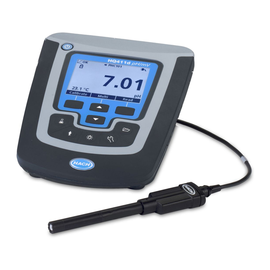
Figure The HQd series meters are available in 3 models: • HQ411d—pH/mV/ORP (Redox) • HQ430d—Multi-parameter, single probe input • HQ440d—Multi-parameter, dual probe inputs Features common to all models: • Automatic probe and parameter recognition • Instrument guided calibration procedures • Calibration data stored in the probe •... -
Page 7: Product Components
If any items are missing or damaged, contact the manufacturer or a sales representative immediately. Figure 2 Meter components 1 HQ440d, HQ430d or HQ411d meter 3 AC/DC power supply with cable 2 AA batteries (pk/4) 4 USB cable (HQ440d, HQ430d models only) English 5... -
Page 8: Installation
Installation C A U T I O N Multiple hazards. Only qualified personnel must conduct the tasks described in this section of the document. Connect to AC power D A N G E R Electrocution Hazard. AC power outlets in wet or potentially wet locations MUST ALWAYS be provided with a Ground Fault Circuit Interrupting (GFCI/GFI) circuit breaker. -
Page 9: User Interface And Navigation
The meter can be powered with AA alkaline or rechargeable NiMH batteries. To conserve battery life, the meter will power off after 5 minutes of inactivity. This time can be changed in the Display Options menu. For battery installation refer to Figure 1. -
Page 10: Display Description
Display description Measurement screen The meter display shows the concentration, units, temperature, calibration status, operator ID, sample ID, date and time (Figure Figure 6 Single screen display 1 Calibration status indicator 9 Time 2 Main measurement value and unit 10 Date 3 IntelliCAL probe type and port indicator 11 Read (OK, Select) 4 Battery status... -
Page 11: Navigation
4 Main measurement value 8 Stability or display lock indicator Dual-screen mode (HQ440d model only) When two probes are connected to the HQ440d meter, the display can show the reading from both probes simultaneously or show just one probe (Figure Note: For probe calibration, change the screen mode to the single screen mode. -
Page 12: Startup
1. Select an option from a list: Use the keys to select an option. If check boxes are shown, more than one option can be selected. Push the LEFT key under Select. Note: To deselect check boxes, push the LEFT key under Deselect. 2. -
Page 13: Connect A Probe
Connect a probe 1. Make sure that the display shows the current time and date. Note: The time stamp for a probe is set when the probe is first connected to the meter. This time stamp makes it possible to record the probe history and record the time when measurements are made. 2. -
Page 14: Use A Sample Id
Use a sample ID The sample ID tag is used to associate measurements with a particular sample location. If assigned, stored data will include the sample ID. 1. Push the key. 2. Select, create or delete a sample ID: Option Description Current ID Select an ID from a list. -
Page 15: View Stored Probe Data
1. Push the key. 2. Select View Data Log to view the stored data. The most recent data point is shown. The top of the screen shows whether the data is from a sample reading, a calibration or a check standard. Push the key to view the next most recent data point. -
Page 16: Change The Report Options
Figure 10 Connection to the printer 1 USB cable 3 AC-DC power supply for printer (optional) 2 Citizen Printer, FCC Part 15B, Class B compliant Change the report options Printed reports for sample data can contain 1, 2 or 3 lines of information. Refer to Examples of printed reports on page 28 for further information. -
Page 17: Open Data Files On A Pc
Model number of probe, for example pHC101, CDC401, LDO101 Probe SN Probe serial number If two probes are connected to the HQ440d meter, the serial number shows “<“ or “>” to identify the port (left or right) the probe was connected to during the reading. - Page 18 Table 1 Spreadsheet column descriptions (continued) Column header name Data description and example values Any settings that affect the Reading Message 1–4 Any message that was shown during the measurement, reading, for example for example “Out of limits”. “NaCl/Non-Linear” Check Std Value Value of the check standard that was used to verify accuracy, for example: 7.00 pH–25 ºC (pH, temp-compensated);...
-
Page 19: Remove Column Headers
Table 1 Spreadsheet column descriptions (continued) Column header name Data description and example values Date/Time POSIX Date and time of reading stored in POSIX format (number of seconds from January 1, 1970) Example: 1149234913 Cal Date/Time POSIX Date and time of calibration stored in POSIX format (number of seconds from January 1, 1970). -
Page 20: Turn Security Options On
Access Options menu, even after Security Options is turned on and a password has been set. After the meter is shut off and powered on again with Security Options on, the Operator Access Options menu is displayed until a valid password is entered. Store the password in a safe and accessible place. -
Page 21: Restricted Operator Access Options Menu
Table 2 Full Access Options (continued) Option Description Date and time Format Date Time Temperature units Set temperature units Language Select language Restricted operator access options menu The Operator Access Options menu is shown at meter startup when Security Options is ON ( Table 3). -
Page 22: Set The Sound Options
Option Description Backlight The display backlight is turned off when the key is pushed. Is it possible to set a time period after which the backlight will automatically power off if no key is pushed. Mode Select Detailed or Big screen size. Detailed will show more information with smaller numbers and text. -
Page 23: Set Auto Measurement Intervals
1. Push the key and select Measurement Mode. 2. Select Mode. 3. Select one of the measurement modes. Option Description Press to Read The sample is measured only when the RIGHT key under Read is pushed. Data is stored in the data log automatically when the stability criteria are met. -
Page 24: View Instrument Information
Table 4 Recommended interval/duration pairs (continued) Interval Duration 1 minute 8 hours 5 minutes 24 hours Note: When 2 probes are connected to the meter, use the next lowest recommended duration time. For example, for a 30-second interval, set the duration to 1 hour to prevent data log overload with 2 probes. View instrument information The instrument information menu shows specific information such as the serial number for the meter or IntelliCAL (R) probe(s). -
Page 25: Download Software Updates
Download software updates To download the most current version of the software, refer to the applicable product page on the manufacturer's website. 1. Transfer the update files to a USB storage device. 2. Follow the instructions in Update the meter software on page 22 to update the software in the meter. -
Page 26: Maintenance
1. The meter software must be version 2.0.0.710 or higher. To download the most current version of the software, refer to the applicable product page on the manufacturer's website. 2. Open the Zip file. 3. Copy the INF file from the software upgrade package to a convenient location on the PC. Note: The INF file must be installed to use the meter manual control from a PC. -
Page 27: Troubleshooting
For battery replacement, refer to Figure 1. Loosen the three battery cover screws and remove the battery cover (Figure 11). Note: Do not remove the screws from the battery cover. 2. Remove the batteries. 3. Install 4 AA alkaline or 4 AA nickel metal hydride (NiMH) batteries. Make sure that the batteries are installed in the correct polarity. - Page 28 Error/Warning Description Solution Probe Not Supported Probe disconnected or Tighten the locking nut on the probe connector. connected improperly Disconnect the probe and then connect the probe again. Software not updated to To download the most current version of the most current version software, refer to the applicable product page on the manufacturer's website.
-
Page 29: Replacement Parts And Accessories
Replacement parts and accessories Note: Product and Article numbers may vary for some selling regions. Contact the appropriate distributor or refer to the company website for contact information. Replacement parts Description Item no. Batteries, Alkaline AA 1938004 Battery cover 9245500 Cable, USB 6 ft (1.8 m), Type A male, Type B male 5924000 Power supply without power cord... -
Page 30: Examples Of Printed Reports
Examples of printed reports Printed reports contain a report header and all stored data for samples, check standards and calibrations. Report header The first line of a report shows the report header (Figure 12). Figure 12 Report header 1 Meter serial number 3 Date and time, 24 h (YYMMDDhhmm) 2 Report label 4 File type extension... - Page 31 Figure 14 Advanced report for sample data—2 lines 1 Probe model 4 Additional units: shows all additional units associated with the reading. 2 Error message (if applicable) 5 Probe settings: shows the highest-priority setting associated with the reading 3 Probe serial number (a “<“ or “>” on the HQ40d meter indicates the probe position) Figure 15 Total report for sample data—3 lines 1 Method name for probe settings...
- Page 32 Figure 17 Calibration report 1 Report type (CL = calibration, IC = current 7 Probe serial number (a “<“ or “>” on the HQ440d calibration) meter indicates the probe position) 2 Parameter (pH, LDO, etc.) 8 Calibration slope/ratio/constant 3 Method name for probe settings 9 Offset—contents vary depending on type of...
-
Page 33: Index
Index modes screen ..............19 AC power connection ..........6 auto-shutoff ............... 19 operator ID ..............12 backlight ..............19 battery replacement ........... 25 Bi-directional Communication ........23 power ................6 big screen mode ............ 8, 19 battery replacement ..........25 printing ............... - Page 36 Tel. +49 (0) 2 11 52 88-320 SWITZERLAND Fax (970) 669-2932 Fax +49 (0) 2 11 52 88-210 Tel. +41 22 594 6400 orders@hach.com info-de@hach.com Fax +41 22 594 6499 www.hach.com www.de.hach.com © Hach Company/Hach Lange GmbH, 2010, 2013, 2016. All rights reserved.