Yaesu FT1DR Operating Manual
144/430mhz digital/ananlog transceiver c4fm fdma
Hide thumbs
Also See for FT1DR:
- Operating manual (90 pages) ,
- Instruction manual (68 pages) ,
- Technical supplement (62 pages)
Table of Contents
Advertisement
Quick Links
/
144/430MHz
DIGITAL/ANALOG
TRANSCEIVER
Operating Manual
C4FM FDMA
Read this information first
Basic Operation
Repeater Operation
Using the Memory
Scanning Function
Using the Digital GM Function
Using the APRS Function
Using the GPS Function
Convenient Functions
Communicating with a
Specific Remote Station
Functions Used As Needed
Appendix
Advertisement
Table of Contents

Related Manuals for Yaesu FT1DR


Summary of Contents for Yaesu FT1DR
- Page 1 144/430MHz DIGITAL/ANALOG TRANSCEIVER Operating Manual C4FM FDMA Read this information first Basic Operation Repeater Operation Using the Memory Scanning Function Using the Digital GM Function Using the APRS Function Using the GPS Function Convenient Functions Communicating with a Specific Remote Station Functions Used As Needed Appendix...
-
Page 2: Table Of Contents
Read this information first ........2 Repeater Operation ..........40 Introduction ..............5 Repeater Operation ..........40 Features of the FT1DR/DE ........5 Communicating Via the Repeater ......40 How to Read This Manual ........6 Tone Calling (1750 Hz) ........40 Checking Bundled Items ........ - Page 3 Table of Contents Registering to a Programmable Memory Searching for the Frequency of the DCS Channel ............63 Used by the Remote Station ......87 Performing Programmable Memory Channel Notification of Call from the Remote Station by Scan ..............64 Vibration of the Vibrator ........
- Page 4 Connecting an external device......143 Setting the time to resume scan Connecting to a PC ........143 SCAN RE-START Function........ 123 Connecting the FT1DR/DE to external Selecting a reception method when devices ............144 scanning stops ........... 124 Data Cable (CT-170) ........144 Setting the range for SCAN .......
-
Page 5: Introduction
* WIRES-X, GM function and APRS instruction manuals are not included in the product package. They are available and may be downloaded from the Yaesu.com website. Please download the WIRES-X function instruction manual from our home page when it is released. -
Page 6: How To Read This Manual
For pressing or turning v while pressing the O key ..Turn v while pressing O. Caution ...Explains caution to observe during operation..Explains operating suggestions or useful tips. Checking Bundled Items FT1DR/DE Antenna Lithium-ion battery pack (FNB-101LI: 7.4 V, 1,100 mAh) -
Page 7: Safety Precautions (Be Sure To Read)
Safety Precautions (Be Sure to Read) Be sure to read the safety precautions to use this product safely. We are not liable for failures and other problems caused due to misuse or use of this product by you or a third party as well as the damages caused through use of this product by you or a third party except in the case where we are ordered to pay for damages under the laws. - Page 8 Do not make very long Do not use any battery charger transmissions. which is not specified by Yaesu. The main body of the transceiver may A fire or failure can result. overheat, resulting in a failure or burns.
- Page 9 If they are installed improperly, the Do not place this transceiver in a FT1DR/DE may fall or drop, resulting in place subject to direct sunlight or an injury or damage. near a heater. Do not place a heavy object on the The transceiver can deform or discolor.
- Page 10 Safety Precautions (Be Sure to Read) Charge the battery pack within the Before discarding the worn battery temperature range from +5 °C to pack, affix tape or the like to its +35 °C (+41 °F to +95 °F). terminals. Charging the battery pack outside this Before using this transceiver in temperature range can cause leak, a hybrid or fuel-saving car, be...
-
Page 11: Before Transmitting Radio Waves
Safety Precautions (Be Sure to Read) About Waterproo¿ ng Feature Conforming to IPX5 When the included antenna and battery pack are installed and the MIC/SP jack, EXT DC IN jack, DATA terminal, and micro SD slot are securely covered with rubber caps, this product is moisture and splash resistant. -
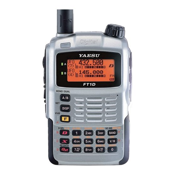
Page 12: Names And Functions Of Controls
It is not waterproofed when an external microphone is connected. Do not connect any microphone which is not specified by Yaesu. A failure can result. n EXT DC IN jack* • When charging the battery pack, connect the a Antenna terminal (SMA)* battery charger (PA-48 or SAD-11B) to this jack. - Page 13 Names and Functions of Controls When pressed The key is pressed When pressed and held When entering a over 1 second after F pressed frequency or recalling When inputting a tag a memory CH Switches between — Starts WiRES-X — radio wave types.
- Page 14 Names and Functions of Controls Wide digital mode (digital communication using C4FM modulation) A-band Wide digital mode (High quality display area digital communication) B-band g Displays a squelch type (See page 84). display area Lights up when the tone encoder Icons function is enabled.
-
Page 15: Basic Operation
Basic Operation Preparation Installing the Antenna Align the antenna with the antenna terminal on the transceiver. Caution Be sure to hold the thick base of the antenna when installing it. Turn the antenna clockwise until it is secured. Cautions z Do not hold the upper part of the antenna when installing or removing it. To do so, the wire inside the antenna may break. -
Page 16: Attaching A Hand Strap
Preparation Attaching a Hand Strap If you attach a hand strap to the transceiver, its string which is inserted in and secured to the strap hole of the transceiver must have a diameter of 1 mm. * The hand strap is not an accessory. Remove the battery pack. -
Page 17: Installing/Removing The Battery Pack
Preparation Installing/Removing the Battery Pack Installing the Battery Pack Insert the bottom tabs of the battery pack in the slots Lock dials at the bottom of the transceiver. Push the battery in until the latches click securely. Caution z When you use the transceiver for the first time after purchase or you have not used it for a long period, charge the battery pack before use. - Page 18 Preparation Battery charger PA-48 or SAD-11B (accessory) Grooves in battery pack Rails Rapid Charger CD-41 (option) Install the Battery Pack Turn off the transceiver. Insert the plug of the battery charger (PA-48 or SAD-11B) in the EXT DC IN jack of the transceiver. Charging starts.
- Page 19 Preparation When charging is complete, remove the plug of the battery charger from the jack of the transceiver. Cautions z Neither transmission nor reception can be performed while charging the battery pack using the supplied battery charger. z Charging may cause noise in the nearby TV or radio. Charge the battery pack with the battery charger as far away as possible from a TV or radio.
-
Page 20: Connecting An External Power Supply For Use In Vehicle (Usa/Exp Version Only)
Preparation Connecting an External Power Supply for Use in Vehicle (USA/EXP version only) The optional external power supply adapter with To cigarette lighter socket of vehicle a cigarette lighter plug (E-DC-5B) allows the transceiver to be used in a vehicle. Turn off the transceiver. - Page 21 Preparation Turn off the transceiver. Connect the optional external power supply Connect the external cable (E-DC-6) to an external power supply. antenna. External power supply Remarks • Connect the red/black wire or white/ red wire to the positive (+) terminal of the external power supply and the black wire to the negative (–) terminal.
-
Page 22: Using A Microsd Memory Card
Do not attempt to forcefully remove mounted microSD memory card. Do not use microSD memory cards other than those specified by Yaesu. For the information on the specified products, please contact Yaesu Amateur Ham Radio Customer Support. - Page 23 Using a microSD memory card Open the microSD cover on the side of the transceiver. Insert the microSD memory card into the card slot until you hear a click. (as shown in the figure at the right). Cautions • Ensure that the microSD memory card is facing the proper direction when mounting it.
-
Page 24: Formatting A Microsd Memory Card
Using a microSD memory card Formatting a microSD memory card Format a new microSD memory card following the steps below before use. Caution Formatting a microSD memory card erases all data saved to it. If you are going to format the microSD memory card you are using, be sure to check the data saved to it before formatting. -
Page 25: Performing Communication
Performing Communication Try communication using the transceiver in the analog communication mode. Follow the procedure below: Turn on the transceiver Adjust the Volume Level Select an Operating Band Select a Frequency Band Turn in to a Frequency Perform Communication Turning on the Transceiver Press and hold P over 1 second. -
Page 26: Adjusting The Volume Level
Performing Communication O Turning off the Transceiver To turn off the transceiver, press and hold P over 1 second. Adjusting the Volume Level You can adjust the transceiver volume level for the A-band and B-band separately. Press A to select the A-band or B-band for which you want to adjust the volume level. -
Page 27: Selecting An Operating Band
Performing Communication Selecting an Operating Band The frequency displayed on the LCD in large letters is the operating band. You can change the frequency of the operating band and activate the transmitter. Each time A is pressed, the operating content displayed on the LCD screen is changed. - Page 28 Performing Communication • On A-band, you can transmit and receive using the 144 MHz and 430 MHz Amateur radio bands. • On B-band, you can transmit and receive using the 144 MHz and 430 MHz Amateur radio bands. In addition, the frequencies on the chart below can be received on A-band and B-band. Chart of A-band and B-band reception frequencies A-band and B-band reception frequencies A-band...
-
Page 29: Selecting A Frequency Band
Performing Communication Selecting a Frequency Band You can select a frequency band to use for the A-band and B-band separately. O Setting a Frequency Band for the A-band Press A to select the A-band. Press B repeatedly to select a frequency band. 50 MHz AM BC FM BC... -
Page 30: Tuning In To A Frequency
Performing Communication Tuning in to a Frequency Tune in to your desired frequency using either of the following methods: (1) Turn O to tune in to your desired frequency. (2) Enter your desired frequency directly using the numeric keys. O Tuning in to your desired frequency with O. Switch to the VFO mode. -
Page 31: Performing Communication
Performing Communication Pressing % repeatedly switches the communication mode as follows. „ [Analog (FM)] [Auto ( FM)] [Digital (DN)] [Digital Wide (VW)] Analog Analog communication using FM mode. „ „ Auto Automatically switches between Analog AM ( AM), Analog „ „... -
Page 32: Selecting Communication Mode
Performing Communication Selecting Communication Mode This transceiver is equipped with AMS (Automatic Mode Select) which automatically selects between 4 modes of transmission to fit the signal being received. Because the transmission is automatically adjusted to that of the other station, not only C4FM digital signals, but analog signals are also recognized. -
Page 33: Listening To The Radio
Listening to the Radio Listening to the AM/FM Radio AM broadcast stations can be easily received using “Preset Memory Receiver” (See page 52), where many major broadcast stations are already saved to this transceiver, or the stations can be directly tuned in by inputting the frequency of the desired broadcast station with the O and key pad. -
Page 34: Miscellaneous Settings
Miscellaneous Settings Setting clock time This transceiver is equipped with an internal clock. The clock is used to display the time, and also to turn the transceiver on or off at a specified time (timer function). Set the clock before using the transceiver for the first time. Enter the Set mode: Press and hold M for over 1 second. -
Page 35: Muting Audio
Miscellaneous Settings Tips • The accuracy of the clock is 30 seconds/month. However, it may vary depending on the environment conditions, such as the temperature. • The transceiver is equipped with a dedicated rechargeable lithium battery for the clock. Normally, the transceiver is powered from the battery pack. When the battery pack is detached or runs out, the lithium battery starts operating automatically. -
Page 36: Changing The Transmission Power Level
Miscellaneous Settings Press p to exit from the Set mode. When the muting function is active, ] appears on the Remark LCD. When the muting function is active, ] blinks on the LCD. Tips • Even if the muting function is activated, the voice is not muted when no signal is received on the operating band. -
Page 37: Adjusting The Squelch Level
Adjust the squelch level as required. Press A to select the desired operating band. On the FT1DR, press F and then T. On the FT1DE, press and hold M over 1 second to enter the Set mode, and then select [4 SIGNALING] [8 SQL LEVEL]. -
Page 38: Changing The Mode Manually
Miscellaneous Settings Tips • For the AIR band (108 MHz to 136.991 MHz), the frequency step “8.33 kHz” can be selected. • For bands covering 250MHz to 300MHz, and bands covering 580 MHz or higher, the frequencies, frequency steps “5 kHz”, “6.25 kHz”, and “15 kHz” cannot be selected. Changing the Mode Manually By default, the reception (RX) is set to “AUTO (Auto Mode)”... -
Page 39: Locking Keys And Switches
Miscellaneous Settings Locking keys and switches To prevent accidental frequency change during operation, keys, switches and O except p switch, T, v, P can be locked. Press P to lock the keys and switches. l appears on the LCD. To unlock a key or switch, press P again. Remark l disappears from the LCD. -
Page 40: Repeater Operation
If you need to access the repeaters which requires a 1750 Hz burst tone for access by the FT1DR (USA/EXP versions), you can set the T switch to serve as a “Tone Call” switch instead. To change the configuration of this switch, use Set Mode [8 CONFIG]... -
Page 41: Repeater Shift
Repeater Shift The FT1DR/DE has been configured, at the factory, for the repeater shifts customary in the country where it is sold. For the 144 MHz band, this usually will be 600 kHz, while the 430 MHz shift will be 1.6 MHz, 7.6 MHz, or 5 MHz (USA version). -
Page 42: Using The Memory
Using the Memory A Wide Variety of Memory Functions The FT1DR/DE transceiver provides the following various types of memory channels in addition to the regular memory channels (numbers 001 to 900). • [Home channels] which can be recalled on each frequency band with one touch of a key. -
Page 43: Registering To Memory Channel
A Wide Variety of Memory Functions Registering to Memory Channel Caution The information such as operating frequency that is registered to memory channels can be corrupted due to wrong operation, static electricity, or electrical noise. Also, it can be erased in the case of a failure or repair. -
Page 44: Split Memory
Press V Press V. “OVERWRITE OK?” appears • To place the FT1DR/DE transceiver in the Memory Channel only mode, use the following procedure, which allows the use of memory channels only. Press V while pressing P to turn on the transceiver. -
Page 45: Recalling Home Channel
A Wide Variety of Memory Functions Recalling Home Channel Press F and then 4. The home channel of the currently selected frequency band appears on the LCD. Tips • For the relationship between the frequency bands and the home channel frequencies, see the table on the next page. -
Page 46: Deleting Memory Channel
A Wide Variety of Memory Functions Deleting Memory Channel Switch to the Memory mode. Press and hold F for over 1 second. Turn O to select the memory channel to delete. Press H. “DELETE?” appears on the LCD for about 3 seconds. Remark To cancel the memory channel deletion operation, press Press H to delete the memory channel. -
Page 47: Assigning A Name To A Memory Channel
A Wide Variety of Memory Functions Assigning a Name to a Memory Channel Example: Assignment of name [YAESU] Switch to the Memory mode. Recall the memory channel to assign a name. Press and hold M for over 1 second to enter the Set mode. -
Page 48: Using Memory Bank
Using Memory Bank Registered memory channels can be sorted according to the intended use. The transceiver allows you to use 24 types of memory banks. A maximum of 100 memory channels can be registered to each memory bank. One memory channel can be registered in two or more memory banks. If the memory channel registered in any memory bank is changed or updated, the content of the corresponding memory channel in the other memory banks is automatically changed or updated. -
Page 49: Recalling Memory Bank
Using Memory Bank Recalling Memory Bank Switch to the Memory mode. Memory channel Bank number number Press B. Pressing B each time toggles between the memory channel number and bank number. Press F and then B. Turn O to select a memory bank. Bank Bank name number... - Page 50 Using Memory Bank Turn O to select [2 BANK NAME]. Press H. Turn O to select a memory bank. Select the number of the memory bank to which you want to assign a name. Bank number Press H to move the cursor to the first character of the bank name.
-
Page 51: Convenient Preset Receiver Memory Channels
Convenient Preset Receiver Memory Channels Frequencies of SP1 Weather Broadcast (10 channels). SP2 International VHF (marine) radio (57 channels) and SP3 Shortwave Broadcasts (89 channels) are preset in the preset receiver memory channels. These channels can be selected in advance from region to region. -
Page 52: Recalling Preset Receiver Memory Channel To Listen To The International Vhf (Marine) Radio
Convenient Preset Receiver Memory Channels Recalling Preset Receiver Memory Channel to Listen to the International VHF (Marine) Radio The frequencies (57 channels) used for the international VHF (marine) radio are registered to the dedicated preset receiver memory channels. Press A to set A-band to the operating band. Press F and then 3 to enter the Preset Receiver mode. - Page 53 Convenient Preset Receiver Memory Channels Frequencies of International VHF (Marine) Radio registered to the preset receiver memory channels Memory channel No. Frequency (MHz) Memory channel No. Frequency (MHz) 156.050 160.650* 156.750 156.100 160.700* 156.800 156.150 160.750* 156.850 156.200 160.800* 156.900 161.500* 156.250 160.850*...
-
Page 54: Recalling Preset Receiver Memory Channel To Listen To The World Broadcast
Convenient Preset Receiver Memory Channels Recalling Preset Receiver Memory Channel to Listen to the World Broadcast The frequencies (89 channels) used for the world broadcast are registered to the dedicated preset receiver memory channels. Press A to set A-band to the operating band. Press F and then 3 to enter the Preset Receiver mode. - Page 55 Convenient Preset Receiver Memory Channels Frequency Broadcast Station Frequency Broadcast Station Name Name Number (MHz) Name Number (MHz) Name 6.055 NIKKEI Japan (Nikkei) 9.595 INDIA India 7.315 NORWAY Norway 11.620 INDIA India 9.590 NORWAY Norway 15.020 INDIA India 9.925 NORWAY Norway 7.190 CHINA...
-
Page 56: Scanning Function
Scanning Function Using the Scanning Function The FT1DR/DE supports the following four scan modes: (1) VFO Scan (2) Memory Channel Scan (3) Programmable Memory Channel Scan (4) Selected Memory Channel Scan VFO Scan Switch to the VFO mode, and then select a band to scan. -
Page 57: Canceling Scanning
Using the Scanning Function Canceling Scanning To cancel scanning, press p. Tips • Even during scanning, you can adjust the squelch in the following procedure: Press F. Press T. Turn O to adjust the squelch. • During scanning, you can save the squelch adjustment in the following procedure: Press F Press T. -
Page 58: Specifying The Frequency You Do Not Want To Scan
Using the Scanning Function Specifying the Frequency You Do Not Want to Scan Start VFO scanning. Start VFO scanning with reference to [VFO Scanning] on page 56. When scanning stops at a frequency you do not want to receive, press and hold F for over 1 second. -
Page 59: Selecting A Reception Method When Scanning Stops
Using the Scanning Function Selecting a Reception Method When Scanning Stops When scanning stops, you can select one of the following three reception methods: (1) The signal is received for the specified period of time, and then scanning resumes. You can specify this period of time in steps of 0.5 second within the range from 2 to 10 seconds. -
Page 60: Specifying A Skip/Selected Memory Channel
Using the Scanning Function • Turn O clockwise.: Scanning is performed toward higher memory channel numbers. Tips Turn O counterclockwise: Scanning is performed toward lower memory channel numbers. • When a signal is received during scanning, scanning stops for 5 seconds and this frequency is received. -
Page 61: Scanning Only The Selected Memory Channel
Using the Scanning Function Tips To cancel a skip/selected memory channel, select [OFF]. Lights when a skip memory channel is specified When it is canceled, the icon on the LCD disappears. Skip memory Selected memory channel channel [SKP] [SELECT] Blinks when a select memory channel is specified Scanning Only the Selected Memory Channel Switch to the Memory mode, and then recall the selected... -
Page 62: Memory Bank Link Scan
Using the Scanning Function • Turn O clockwise: Scanning is performed toward higher memory channel numbers. Tips Turn O counterclockwise: Scanning is performed toward lower memory channel numbers. • When a signal is received during scanning, scanning stops for 5 seconds and this frequency is received. -
Page 63: Programmable Memory Channel Scan (Pms)
Using the Scanning Function O Canceling Bank Link Scanning Press F and then B. Recall the memory bank for which bank link scanning was specified. Press V. The memory bank number changes from [b] to [B], indicating that the bank link has been deactivated. -
Page 64: Performing Programmable Memory Channel Scan
Using the Scanning Function Performing Programmable Memory Channel Scan The programmable memory channel scan allows you to scan a specified frequency range within the same frequency band. Switch to the Memory mode. Recall a PMS memory channel to which the lower limit frequency or upper limit frequency is registered. -
Page 65: Using The Digital Gm Function (Digital Group Monitor Function)
Using the Digital GM Function (Digital Group Monitor Function) What is the GM function? The Digital GM (Group Monitor) Function automatically checks if there is another transceiver operating on the same frequency with the GM function within transmission range, and displays the direction, distance and other information for each detected callsign on the LCD. - Page 66 Standard Operation of the GM Function O Registering IDs of friends in a group and using GM function only between registered members Set a group with a name such as [Touring] or [Camp], and only show members registered to that group. Group Name Example of display when Group is set For group setting and instruction on how to register members to a group, refer to the GM...
-
Page 67: Using The Aprs Function
Using the APRS Function What is the APRS (Automatic Packet Reporting System)? Although there are several functions that display position information using GPS in amateur radios, the APRS is data communication system that transmits data such as position information and messages using a format proposed by Bob Bruninga of WB4APR. -
Page 68: Using The Gps Function
Using the GPS Function What is GPS? GPS (Global Positioning System) is a space-based satellite navigation system that provides location and time information anywhere on the earth. It was developed by the U.S. Department of Defense as a military system. It receives signals from three or more of about 30 GPS satellites flying at an altitude of about 20,000 km, and displays the current position (latitude, longitude, and altitude) within a tolerance of several meters. -
Page 69: Method Of Positioning By Gps
Method of Positioning by GPS Displaying Current Position Information of Your Station Turn on the transceiver. Press and hold M for over 1 second to enter the Set mode. Turn O to select [1 DISPLAY]. Press H. Turn O to select [1 GPS POWER]. Press H. - Page 70 Method of Positioning by GPS About Positioning by GPS “Positioning” refers to calculation of your current position from the satellite orbit information and radio propagation time. At least three satellites need to be acquired for successful positioning. If positioning fails, move away from buildings as far as possible and stand in an area with open sky.
-
Page 71: Saving Gps Information (Gps Log Function)
Using the saved data and a personal computer, tracks can be displayed with commercially sold map software*. * Map software, and methods of use are not supported by YAESU. Check that the GPS function is active. If it is not active, refer to page 68 and enable the GPS function. -
Page 72: Explanation Of Gps Screen And Operation
Explanation of GPS Screen and Operation Activating the GPS function displays the following information on the LCD. a Compass: North-UP (North is always up) Heading-UP: Heading-UP: (When B is pressed, the direction in which you are heading is always up. A white arrow icon appears. -
Page 73: Smart Navigation Function
Explanation of GPS Screen and Operation Tips • You can change the unit of GPS data by selecting [9 APRS] [22 GPS UNIT] in the Set mode. • When the GPS function is used, the accurate time data (date and time) obtained from GPS appears on a 24 hour basis. -
Page 74: Description Of The Back Track Function Screen
Smart Navigation Function O Backtrack Function By registering a point of departure beforehand, the distance and direction to the registered position from your current position can be displayed in real-time. O Registering your current position (point of departure) (up to 3 positions can be registered) Press M to open the Backtrack screen. -
Page 75: Convenient Functions
Convenient Functions Dual Reception (DW) Function The FT1DR/DE is equipped with the following 3 types of Dual Reception Functions: (1) VFO Dual Reception (2) Memory Channel Dual Reception (3) Home Channel Dual Reception The transceiver checks the standby side signal reception over the frequency registered to the selected memory channel (Priority Memory Channel) once approximately every 5 seconds. -
Page 76: Memory Channel Dual Reception
Dual Reception (DW) Function Press F and then V to start Dial Dual Reception, and [VDW] appears on the LCD. Press V stop the Dial Dual Reception. Memory Channel Dual Reception Memory channel Priority memory channel Switch to the Memory mode. Press and hold F over 1 second to enter the Write mode;F and the channel number blink on the LCD. -
Page 77: Af-Dual Function For Simultaneous Signal Reception Over The Other Frequency While Listening To The Radio
Dual Reception (DW) Function Caution Be sure to set a memory channel as the Priority Memory Channel for standby before using this function. Tips • The Priority Memory Channel is set to the Memory Channel number 1 by default. • Pressing and holding M over 1 second and changing the Set mode option allows you to use this function more conveniently. -
Page 78: Setting The Resumption Time Of Radio Reception
Dual Reception (DW) Function Tips • For broadcast station frequencies, refer to “Preset Broadcast Station Frequencies List (See page 54)” or a commercially sold frequencies list. • AF-DUAL reception function can be used for the radio frequency registered to the memory bank. •... -
Page 79: Using The Dtmf Function
Dual Reception (DW) Function Display Operation Transmission: 1 While receiving radio broadcast and ham radio band frequencies (A-band second to 10 seconds and B-band) on standby simultaneously with [AF-DUAL Reception Function], the transceiver switches signal reception to the standby upon detecting it. -
Page 80: Confirming The Entered Dtmf Code By The Sound
Using the DTMF Function Press p to set the DTMF code and exit from the Set mode. Confirming the entered DTMF code by the sound Press and hold M for over 1 second to enter the Set mode. Turn O to select [4 APRS]. Press H. -
Page 81: Sending A Dtmf Code Manually
Using the DTMF Function Sending a DTMF Code Manually Press and hold M for over 1 second to enter the Set mode. Turn O to select [4 SIGNALING]. Press H. Turn O to select [4 DTMF MODE]. Press H. Turn O to select [MODE]. Press H. -
Page 82: Searching For Signals With The Signal Strength Graph
In addition, image data can be transmitted to other transceivers* by pressing the (Send Image Button] on the camera mounted on speaker microphone. * Refer to the Yaesu homepage or catalog for the models of transceiver to which images can be transferred. - Page 83 Taking picture with the optional camera mounted on speaker microphone. Lens Aim this lrns towards the object to photograph. Send Image Button Do not touch the lens with fingers or other objects. A picture just taken can be sent. Shutter Button Press this button to take a picture.
-
Page 84: Communicating With A Specific Remote Station
Communicating with a Specific Remote Station Using the Tone Squelch Function The tone squelch opens the squelch only when a signal containing the specified frequency tone is received. Use of the digital code squelch (DCS) opens the squelch only when a signal containing the specified DCS code is received. The tone squelch function mutes monitoring the communications between other stations, even when listening for a call by a specific station for a long time. -
Page 85: Selecting A Tone Frequency
Using the Tone Squelch Function Display Operation Turns on the no-communication squelch function for radios ([PR] PR FREQ appears.). You can specify no-communication signal tone frequencies within the range from 300 Hz to 3000 Hz in steps of 100 Hz. Turns on a new pager function ([PAG] appears). -
Page 86: Searching For The Frequency Of The Tone Squelch Used By The Remote Station
Using the Tone Squelch Function Searching for the Frequency of the Tone Squelch Used by the Remote Station The frequency of the tone squelch used by the remote station can be searched for and displayed. Enter the Set mode: Press and hold M for over 1 second. Turn O to select [4 SIGNALING]. -
Page 87: Searching For The Frequency Of The Dcs Used By The Remote Station
Using the Tone Squelch Function Turn O to select a DCS code. Quickly press M 3 times to set the DCS code and exit from the Set mode. By default, the DCS code is set to [023]. Searching for the Frequency of the DCS Used by the Remote Station The DCS code used by the remote station can be searched for and displayed. -
Page 88: Notification Of Call From The Remote Station By Vibration Of The Vibrator
Using the Tone Squelch Function Notification of Call from the Remote Station by Vibration of the Vibrator Set the vibrator to alert you of a call from a remote station containing a corresponding CTCSS tone or DCS code. Enter the Set mode: Press and hold M over 1 second. -
Page 89: Notification Of A Call From A Remote Station By The Bell
Using the Tone Squelch Function Turn O to select [SELECT]. Press H. Turn O to select a vibrator operation mode. Remark Default: MODE1 MODE1 The vibrator vibrates continuously. MODE2 The vibrator operates at long intervals. MODE3 The vibrator operates at short intervals. Press p. -
Page 90: Calling Only A Specific Station New Pager Function
Using the Tone Squelch Function Turn O to select [1 BELL]. Press H. Turn O to select [RINGER]. Press H. Turn O to select the number of times the bell rings. Remark Default: Once You can select the number of times the bell rings from among 1 to 20 times, or continuous. -
Page 91: Setting The Code Of Your Station
Using the Tone Squelch Function Setting the Code of Your Station Set the personal code (your code) to be called by other stations. Enter the Set mode: Press and hold M over 1 second. Turn O to select [4 SIGNALING]. Press H. -
Page 92: Calling A Specific Station
Using the Tone Squelch Function Calling a Specific Station Enter the Set mode: Press and hold M over 1 second. Turn O to select [4 SIGNALING]. Press H. Turn O to select [11 SQL TYPE]. Press H. Turn O to select [PAGER]. Set the new pager function: Press M. -
Page 93: Being Called By The Remote Station (Standby Operation)
Using the Tone Squelch Function Being Called by the Remote Station (Standby Operation) If you use the new pager function on the same frequency as the remote station, the [PAG] icon displayed on the LCD changes to [PIN], alerting that you have been called by the remote station. -
Page 94: Functions Used As Needed
Functions Used As Needed Set Mode Using the Set Mode The Set mode allows you to select various functions from a list so you can use your transceiver more conveniently. Enter the Set mode: Press and hold M for over 1 second. Turn O to select a Set mode option. -
Page 95: Set Mode Option List
Set Mode Press % while pressing V, and P. Then turn the transceiver on. When a beep is heard, release the keys. When [SET MODE RESET PUSH F KEY] appears, press F. A beep is emitted. To cancel resetting, press any key other than Set Mode Option List Set mode option No./ Setting Item... - Page 96 Set Mode Set mode option No./ Setting Item Reference Description of function setting Item (Bold letters: Default) page 2-2-2 SQL TYPE Select SQL Type in the DIGITAL SQL TYPE: OFF / CODE / mode. BREAK CODE: 001 to 126 2-2-3 DIGI POP UP Set the POP UP time.
- Page 97 Set Mode Set mode option No./ Setting Item Reference Description of function setting Item (Bold letters: Default) page 4-3 DCS INVERSION Select a combination of DCS RX (Reception): inversion codes in terms of -NORMAL (Homeomorphic) / communication direction. INVERT (Inversion) / BOTH (Both Phase) / NORMAL (Homeomorphic) TX (Transmission):...
- Page 98 Set Mode Set mode option No./ Setting Item Reference Description of function setting Item (Bold letters: Default) page 6 GM 6-1 LANGUAGE Select the language to use for JAPANESE – writing a message, etc. ENGLISH 6-2 DELETE GROUP Delete a registered group. –...
- Page 99 Set Mode Set mode option No./ Setting Item Reference Description of function setting Item (Bold letters: Default) page 8-13 PTT DELAY Set the PTT delay time. OFF / 20ms / 50ms / 100ms / 200ms 8-14 RPT ARS Turn the ARS function on/off. ON / OFF 8-15 RPT SHIFT Select a repeater shift direction.
- Page 100 9-6 APRS MSG GROUP Set group filter for receiving G1: ALL****** – messages. G2: CQ******* G3: QST****** G4: YAESU**** B1: BLN****** B2: BLN* B3: BLN* 9-7 APRS MSG TXT Enter standard message text 1 to 1 to 8 ch –...
- Page 101 Set Mode Set mode option No./ Setting Item Reference Description of function setting Item (Bold letters: Default) page 9-9 APRS POPUP Set the beacon type, the GRP: – message type and the time of the OFF / ALL2s to ALL60s / popup display.
- Page 102 Set Mode Set mode option No./ Setting Item Reference Description of function setting Item (Bold letters: Default) page 9-13 BEACON INFO Set the transmission beacon AMBIGUITY: – information. OFF / 1 dig to 4dig SPD / CSE: ON / OFF ALTITUDE: ON / OFF 9-14 BEACON Set a beacon automatic sending...
-
Page 103: Displaying The Gps Screen
Set Mode Set mode option No./ Setting Item Reference Description of function setting Item (Bold letters: Default) page 9-26 POSITION Set up the position comment Off Duty / En Route / – COMMENT function. In Service / Returning / Committed / Special / Priority / Custom 0 to 6 / EMERGENCY! 9-27 SmartBeaconing Set the smart beaconing function. -
Page 104: Setting The Display Method Of The Remote Station Information
Set Mode Setting the display method of the remote station information Set the display method of the remote station information when using the GM Function. Enter the Set mode: Press and hold M for over 1 second. Turn O to select [1 DISPLAY]. Press H. -
Page 105: Setting The Search Channels For The Band Scope Function
Set Mode Setting the search channels for the BAND SCOPE function You can set the number of channels to be displayed for the band scope when the BAND SCOPE function is used. Enter the Set mode: Press and hold M for over 1 second. Turn O to select [1 DISPLAY]. -
Page 106: Selecting A Display Language
Set Mode Selecting a Display Language You can select a display language from Japanese and English. Enter the Set mode: Press and hold M for over 1 second. Turn O to select [1 DISPLAY]. Press H. Turn O to select [6 LANGUAGE]. Press H. -
Page 107: Adjusting The Lcd Backlight And Keypad Key Light Brightness Level
Set mode. Changing the Opening Message Displayed Immediately after Power-on You can select the message displayed under the “YAESU” logo from among four types: “no message”, “power supply voltage”, “message comprising up to 16 characters”, and “callsign”. Enter the Set mode: Press and hold M for over 1 second. -
Page 108: Measuring The Battery Voltage And The Transceiver Temperature Power Supply Voltage Measurement Function/Temperature Measurement Function
Remark Default: CALLSIGN Display Display Condition NORMAL The YAESU logo appears immediately after power-on. Immediately after power-on, the reception frequency, etc. appear without displaying an opening message. The power supply voltage and time appear immediately after power-on. MESSAGE A message comprising up to 16 characters appears immediately after power-on. -
Page 109: Changing The Display Pattern Of The Po Meter
Set Mode Tips • The display changes as follows depending on the type of the power supply used. Battery pack: “Lit” Battery case: “Dry” External power supply adapter: “Ext” • During mono band reception, the voltage can be displayed on the LCD constantly (See page 27). •... -
Page 110: Setting The Transmission Modulation Level
Set Mode Turn O to select [1 MODE]. Press H. Turn O to select [2 ANTENNA ATT]. Press H. Turn O to select [ON]. Remark Default: OFF Press p to save the attenuator function setting, and exit the Set mode. •... -
Page 111: Changing The Mode Manually
Set Mode Changing the mode manually Manually switch to an optimum mode (radio wave type) according to the frequency band. For more details, see “Changing the Mode Manually” on page 38. Switching between digital and analog mode You can set digital and analog mode switching and digital transmission mode. Enter the Set mode: Press and hold M for over 1 second. -
Page 112: Setting The Squelch Type For The Digital Mode
Press H. Turn O to select a squelch type. OFF: Voice is always output upon receiving a digital signal from a Yaesu transceiver. CODE: Voice is output only when receiving a signal with a corresponding SQL CODE. BREAK: Voice is output regardless of any squelch code when the remote station transmits with BREAK set. -
Page 113: Displaying The Version Of The Dsp Program
Set Mode Turn O to select [3 DIGI POPUP]. Press H. Turn O to select the display method. OFF: Does not display the remote station information. BND2s to 60s: Set the time to display the remote station information (2 to 60 seconds). BNDCNT: Always display the remote station information. -
Page 114: Muting Voice
Set Mode Turn O to select [3 AUDIO]. Press H. Turn O to select [1 MIC GAIN]. Press H. Turn O to select a microphone sensitivity level. Select a microphone gain level from the following: LEVEL 1 (Lowest sensitivity) to LEVEL 9 (Highest sensitivity) Remark Default: LEVEL 5... -
Page 115: Setting Memory Bank Link
Set Mode Turn O to select [3 AUDIO]. Press H. Turn O to select [4 VOL MODE]. Press H. Turn O to select [AUTO BACK]. Remark Default: NORMAL Usually adjust the sound volume by turning O while pressing v. If the [AUTO BACK] is selected, the sound volume adjustment mode will be automatically canceled after you have pressed v to enter the sound volume adjustment mode and return to the frequency display screen. -
Page 116: Assigning A Name To A Memory Bank
Set Mode Assigning a name to a memory bank A memory bank can be assigned a name with up to 16 characters. For more details, see “Assigning Name to Memory Bank” on page 49. Assigning a name to a memory channel Memory channels and home channels may be assigned a name (memory tag) such as a callsign or broadcast station name. -
Page 117: Registering To A Memory Channel With The Lowest Memory Channel Number Memory Channel Write Function
Set Mode Registering to a memory channel with the lowest memory channel number Memory Channel Write Function When registering to a memory channel. you can display an unregistered memory channel with the lowest memory channel number. Enter the Set mode: Press and hold M for over 1 second. -
Page 118: Setting The Transmission Method Of The Dtmf Code
Set Mode Turn O to select [3 DCS INVERSION]. Press H. Turn O to select a phase. When a phase is selected for the reception side, the phase for transmission side is automatically determined. Reception: [Homeomorphic], [Both Phase], [Inverted Phase], [Homeomorphic], [Both Phase], [Inverted Phase] Transmission: [Homeomorphic], [Inverted Phase], [Inverted Phase], [Inverted Phase], [Homeomorphic], [Homeomorphic]... -
Page 119: Adjusting The Squelch Level Sql Level Function
Set Mode Turn O to select [7 PR FREQUENCY]. Press H. Turn O to tune in to a frequency. Select no-communication squelch frequency in steps of 100 Hz. Remark Default: 1600 Hz Press p to set the no-communication squelch function, and exit the Set mode. - Page 120 Set Mode Turn O to select [9 SQL S-METER]. Press H. Turn O to select a setting value. Select a S-Meter level with reference to the table shown below. Remark Default: OFF Press p to save the selected S-Meter level, and exit the Set mode.
-
Page 121: Setting The Squelch Type For Transmission And Reception Sql Expantion Function
Set Mode Setting the squelch type for transmission and reception SQL EXPANTION FUNCTION Squelch types set beforehand can function separately for transmission and reception. Enter the Set mode: Press and hold M for over 1 second. Turn O to select [4 SIGNALING]. Press H. -
Page 122: On/Off For The Weather Alert Feature
Set Mode Turn O to select [13 TONE-SRCH]. Press H twice. Turn O to select MUTE to [ON]. Remark Default: ON Press M. Turn O to select [SPPED]. Press H. Turn O to select SPEED to [Rapid]. Remark Default: FAST Press p to save the Tone Search setting and exit the Set mode. -
Page 123: Turning Illumination Off When Scanning Stops Scan Lamp Function
Set Mode Turn O to select [1 DW TIME]. Press H. Turn O to select the monitoring interval. Interval can be selected from 0.1 SEC to 10 SEC. Remark Default: 5 seconds Press p to save the priority memory channel monitoring interval setting and exit the Set mode. -
Page 124: Selecting A Reception Method When Scanning Stops
Set Mode Turn O to select [3 SCAN RE-START]. Press H. Turn O to select the time to resume scanning. Select from 0.1 SEC to 10 SEC. Remark Default: 2 seconds Press p to set the resume scanning time, and exit the Set mode. -
Page 125: Turning Off The Power Automatically Apo Function
Set Mode Turn O to select the range for scanning. Mode Display* Operation Status Scans all bands within the range from the current frequency to 108-999 MHz. VFO Mode Scans the current band (see the table on the next page) starting with the BAND current frequency. -
Page 126: Preventing Accidental Transmission Busy Channel Lockout (Bclo) Function
Set Mode Tips • When the auto power-off function is active, the [ icon appears on the LCD. • Once the time for automatic power-off is set, it is retained until “OFF” is selected in step 6 of the above-mentioned procedure. (The next time you turn the transceiver on, if you perform no operation for the set period of time, the transceiver will automatically turn itself off.) Preventing accidental transmission... -
Page 127: Turning Off The Busy Indicator
Set Mode Turn O to select [SELECT]. Press H. Turn O to select [OFF]. Remarks Default: KEY&SCAN Display Description Mutes the beep. KEY&SCAN Emits a beep when a key is operated or scanning stops. Emits a beep when a key is pressed. Press M. -
Page 128: Setting The Clock Shift For The Micro Computer Clock Type Function
Set Mode Setting the clock shift for the micro computer Clock Type Function The micro computer Clock Shift function may be set to reduce internal high frequency spurious interference signals. Select [A] for normal use. Enter the Set mode: Press and hold M for over 1 second. Turn O to select [8 CONFIG]. -
Page 129: Permitting Transfer Of Home Channel Frequency To Vfo
Set Mode Tips • Data saved to the microSD memory card is saved in xxx.LOG format. • Saved data can be viewed with PC applications*. * PC applications are not supported by our company. Permitting Transfer of Home Channel Frequency to VFO You can use the set operation to transfer home channel frequency information to the VFO. -
Page 130: Setting The Conditions For Locking Lock Function
Set Mode Setting the conditions for locking LOCK Function Conditions for activating Lock Function, such as keys, O, and p, can be set. Enter the Set mode: Press and hold M for over 1 second. Turn O to select [8 CONFIG]. Press H. -
Page 131: Turning On/Off The Transceiver At The Specified Time Timer Function
Set Mode Turning on/off the transceiver at the specified time Timer Function You can turn the transceiver to turn on/off at the set time. Before using this function, adjust the clock. See “Setting clock time” on page 34. Enter the Set mode: Press and hold M over 1 second. - Page 132 Set Mode Turn O to enter the first character of the password. Enter the first character (0-9. A to D, ¼, and #) of the password. Press H. The cursor moves to the next character position. Repeat steps 7 and 8 to enter the remaining three characters.
-
Page 133: Setting The Ptt Delay Time Ptt Delay Function
Set Mode Setting the PTT delay time PTT DELAY Function You can set the time for actual transmission to start after p is pressed. Enter the Set mode: Press and hold M for over 1 second. Turn O to select [8 CONFIG]. Press H. -
Page 134: Setting The Direction For Repeater Shift Rpt Shift Function
Set Mode Setting the direction for repeater shift RPT SHIFT Function You can set the direction of repeater shift. Enter the Set mode: Press and hold M for over 1 second. Turn O to select [8 CONFIG]. Press H. Turn O to select [15 RPT SHIFT]. Press H. -
Page 135: Disabling Reception While No Signal Is Received Reception Save Function
Set Mode Disabling reception while no signal is received Reception Save Function To reduce power consumption, the reception function can be turned off when not receiving a signal. Enter the Set mode: Press and hold M for over 1 second. Turn O to select [8 CONFIG]. -
Page 136: Setting The Frequency Selection Range For Operation In The Vfo Mode Vfo Mode Function
Set Mode Turn O to select [20 TOT]. Press H. Turn O to select the time. Set the time for the transceiver to automatically return to the reception state in steps of 30 seconds. OFF/30 SEC to 10 MIN Remark Default: OFF Press p to save the TOT function setting, and exit the Set mode. -
Page 137: Notification Of A Call From A Remote Station By Vibration
Set Mode Notification of a call from a remote station by vibration The vibrator function may be set to notify you of a call from a remote station. For details, see “Notification of Call from the Remote Station by Vibration of the Vibrator” on page 88. -
Page 138: Saving/ Loading Group Id Information To/From Microsd Memory Card
Set Mode Turn O to select [2 MEMORY CH]. Press H. Turn O to select [Write to SD] or [Read from SD]. Write to SD: A beep is heard and [Completed] appears when writing to SD finished. Read from SD: A beep is heard when loading from SD finished and the transceiver restarts with the settings read from the microSD memory card. -
Page 139: Formatting A Microsd Memory Card
Set Mode Press H. Write to SD: A beep is heard and [Completed] appears when writing to SD finished. Read from SD: A beep is heard when loading from SD finished and the transceiver restarts with Blinks when writing the settings read from the microSD memory card. -
Page 140: Registering Callsign
Set Mode Registering CALLSIGN The CALLSIGN used in the digital mode can be registered with up to 10 alphanumeric characters. Enter the Set mode: Press and hold M for over 1 second. Turn O to select [12 CALLSIGN]. Press H. Enter the characters using keypad keys. -
Page 141: Using The Transceiver For Packet Communication
Set Mode Using the transceiver for packet communication You can perform packet communication with your transceiver by connecting TNC (Terminal Node Controller) using an optional connection cable (CT-44). 10 F 2 kΩ After TNC is connected, set the level of output to TNC by adjusting the sound volume level of your transceiver. -
Page 142: Clone Operation
Data and various settings saved in your transceiver can be copied to another FT-1DR transceiver. Turn off the power of both FT1DR/DE transceivers and connect an optional clone cable (CT-168) to the DATA terminal of each transceiver. Press P while pressing F on each transceiver. -
Page 143: Connecting An External Device
• For more details, see the Set mode option, [9 APRS] [17 COM PORT SETTING]. Connecting to a PC Connecting a PC to the data terminal of the FT1DR/DE using the PC Connection Cable (SCU-18) accessory will enable data transmission or updating firmware as described below. -
Page 144: Connecting The Ft1Dr/De To External Devices
Set Mode To use the SCU-18, install a dedicated driver to the PC. For downloading the dedicated driver and installation manual, please go to the YAESU website homepage (http://www.yaesu.com). Connecting the FT1DR/DE to external devices Position information data can be exchanged between commercially sold GPS receivers or other external devices by using the optional Data Cable (CT-170) or the Data Cable (CT-176). -
Page 145: Data Cable (2.5 ) (Ct-176)
Set Mode Data Cable (2.5 ) (CT-176) a RXD (Serial data input [FT1DR/DE a TXD (Serial data output [FT1DR/DE External External Equipment]) Equipment]) b TXD (Serial data output [FT1DR/DE b RXD (Serial data input [FT1DR/DE External External Equipment]) Equipment]) c GND... -
Page 146: Appendix
Availability of accessories may vary. Some accessories are supplied as standard per local requirements, while others may be unavailable in some regions. Consult your Yaesu Dealer for details regarding these and any newly-available options. Connection of any non-Yaesu approved accessory, should it cause... -
Page 147: If You Suspect Malfunction Check The Following Items Before Requesting For Repair
Is the voltage of the battery pack or external power source correct? Check the remaining charge on the battery pack. In addition, using a power supply where voltage drops during transmission will prevent the FT1DR/DE from operating on full capability. -
Page 148: The Battery Pack Cannot Be Charged Or Battery Power Depletes Immediately After Charging
The battery pack cannot be charged or battery power depletes immediately after charging. Is the battery pack being charged with a charger specified by Yaesu? Charge the battery pack using the accessory battery charger (PA-48B or SAD-11B) or the rapid charge cradle (CD-41). -
Page 149: Index
Communicating with a apecific remote station ......84 Communication mode..............32 Confirming the entered DTMF code by the sound....80 Activating the GPS function .............68 Connecting the FT1DR/DE to external devices .....144 Adjusting the LCD backlight and keypad key light brightness level ..................107 Adjusting the LCD contrast level ...........106 Adjusting the microphone sensitivity ........ - Page 150 Index Password function ..............131 PC connection cable (SCU-18) .........6, 146 Performing communication ..........25, 31 GM function ................65 Performing programmable memory channel scan....64 *web Permitting transfer of home channel frequency to VFO ..129 GPS ..................68 PMS ..................63 Group monitor function ............65 PMS memory channel .............63 *web Positioning by GPS..............70...
- Page 151 Index Searching for the frequency of the tone squelch used by the remote station ................86 Select a tone squelch type ............84 Taking picture ................82 Selected memory channel ............60 Taking picture with the optional camera mounted on speaker Selecting a band ..............29 microphone ................82 Selecting a DCS code .............86 Temperature measurement function ........108...
-
Page 152: Specifications
Specifications O General Frequency Range A (Main) Band RX: 0.5 ~ 1.8 MHz (AM Radio) 1.8 ~ 30 MHz (SW Radio) 30 ~ 76 MHz (50 MHz HAM: USA version) 30 ~ 88 MHz (50 MHz HAM: EXP/EU version) 76 ~ 108 MHz (FM Radio: USA version) 88 ~ 108 MHz (FM Radio: EXP/EU version) 108 ~ 137 MHz (Air Band) 137 ~ 174 MHz (144 MHz HAM) - Page 153 Specifications O Transmitter RF Power Output: 5 W (@ 7.4 V or EXT DC) Modulation Type: F1D, F2A, F2D, F3E: Variable Reactance modulation F7W: 4 FSK (C4FM) Spurious Emission: At least 60 dB below (@TX Power Hi, L3, L2) At least 50 dB below (@TX Power L1) O Receiver Circuit Type: AM, NFM: Double-Conversion Super heterodyne...
- Page 154 1. Changes or modifications to this device not expressly approved by YAESU MUSEN could void the user’s authorization to operate this device. 2. This device complies with part 15 of the FCC Rules. Operation is subject to the following two conditions: (1) This device may not cause harmful interference, and (2) this device must accept any interference including received, interference that may cause undesired operation.
-
Page 155: Declaration Of Conformity
Declaration of Conformity We, YAESU UK LTD. certify and declare under our sole responsibility that the following equipment complies with the essential requirements of the Directive 1999/5/EC and 2011/65/EU. Type of Equipment: Dual Band Digital Transceiver Brand Name: YAESU Model Number:... - Page 156 YAESU MUSEN CO., LTD. Copyright 2013 YAESU MUSEN CO., LTD. Tennozu Parkside Building All rights reserved. 2-5-8 Higashi-Shinagawa, Shinagawa-ku, Tokyo 140-0002 Japan No portion of this manual may be reproduced YAESU USA without the permission of 6125 Phyllis Drive, Cypress, CA 90630, U.S.A.