Grizzly EXTREME G0513X2 Owner's Manual
Extreme series 17" 2 hp / 19" 3 hp bandsaw
Hide thumbs
Also See for EXTREME G0513X2:
- Parts list (5 pages) ,
- Owner's manual (108 pages) ,
- Owner's manual (108 pages)
Table of Contents
Advertisement
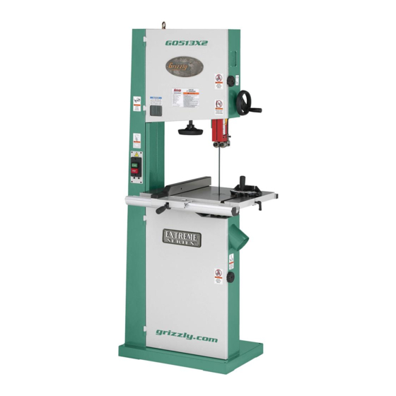
MODEL G0513X2
17" BANDSAW
MANUAL INSERT
The Model G0513X2 is the same machine as the Model G0513X except for the cast iron trunnion assembly.
Except for details given in this insert, the content in the Model G0513X owner's manual is the same for both
machines. Before operating your new machine, you MUST read and understand this insert and the entire
Model G0513X manual to reduce the risk of injury from improper use or setup.
If you have any further questions about this manual insert or the differences between the Model G0513X2
and the Model G0513X, contact our Technical Support at (570) 546-9663 or email techsupport@grizzly.
com.
COPYRIGHT © MAY, 2007 BY GRIZZLY INDUSTRIAL, INC.
WARNING: NO PORTION OF THIS MANUAL MAY BE REPRODUCED IN ANY SHAPE
OR FORM WITHOUT THE WRITTEN APPROVAL OF GRIZZLY INDUSTRIAL, INC.
#BL9289 PRINTED IN TAIWAN
Advertisement
Table of Contents

Related Manuals for Grizzly EXTREME G0513X2


Summary of Contents for Grizzly EXTREME G0513X2
- Page 1 MANUAL INSERT The Model G0513X2 is the same machine as the Model G0513X except for the cast iron trunnion assembly. Except for details given in this insert, the content in the Model G0513X owner's manual is the same for both machines.
- Page 2 G0513X2 Main Parts G0513X2 Manual Insert...
- Page 3 G0513X2 Fence/Guides Parts ������ ������ ������ ������ ����� ������ ������ ������ ����� ����� ����� ������ ��� ��� ��� ��� ��� ��� ��� ��� ��� ��� ��� ��� ��� ��� ��� ��� ��� ��� ��� ��� G0513X2 Manual Insert ������ ������...
- Page 4 G0513X2 Parts List REF PART # DESCRIPTION P0513X001 BUSHING PSS01M SET SCREW M6-1 X 10 P0513X003 BUSHING P0513004 LIFTING EYE BOLT M10-1.5 P0513005 MACHINE BODY PSS07M SET SCREW M5-.8 X 5 P0513X007 BUSHING PW03M FLAT WASHER 6MM PWRCRD220L POWER CORD...
- Page 5 121-29 PH7587029 SPACER PLATE P0513X122 GEAR P0513X123 FIXED BOLT P0513X124 COVER PSB11M CAP SCREW M8-1.25 X 16 P0513X126 TABLE 17" X 24" G0513X2 Manual Insert PART # DESCRIPTION P0513X127 TABLE INSERT P0513X128 TABLE PIN P0513X129 LOCATE BUSHING P0513X130 BUSHING PSBS01M BUTTON HD CAP SCR M8-1.25 X 20...
-
Page 6: G0513X2 Labels
MUST maintain the original location and readability of the labels on the machine. If any label is removed or becomes unreadable, REPLACE that label before using the machine again. Contact Grizzly at (800) 523-4777 or www.grizzly.com to order new labels. ���... - Page 7 ������������ � ������������������������������������������������������������������������������������������������������������������������������������������ �������������� ����������� � ����������������������������������������������������������������������������������������������������������������������������������������������� ������������������ ������� ���������� �������������������������������������������������������������������������������������������������������������������������������������������������������������������� ��� ������������������������������ � ���������������������������������������������������������������������������������������������������������������������������������� �� ����� ����������� ���������������������� � ������������������������������������������������������������������������������������������������������������������������������������������ ��� ������������������������������������������������������������������������������������������������������������������������������������������������������������������� ������������� � ������������������������������������������������������������������������������������������������������������������������������������������������ ������������ ����� ������� G0513X2 Manual Insert ������� ���� ����� ����� ������� � � � � � �...
- Page 8 ������������������������������������������������� ���������������������������������� ����������������������� ���������������������������������� ����������������������������������� ��������������������� ������������������� �������������������������������������������������������������������� �������������������� ��������� � ������� � � ����������������� ����� ������� � � � � � � � � � � � � � � � � ���� � �� � G0513X2 Manual Insert...
- Page 9 MODEL G0513X/G0514X/G0514X3 EXTREME SERIES BANDSAW OWNER'S MANUAL COPYRIGHT © JANUARY, 2006 BY GRIZZLY INDUSTRIAL, INC. REVISED FEBRUARY, 2007 (TR) WARNING: NO PORTION OF THIS MANUAL MAY BE REPRODUCED IN ANY SHAPE OR FORM WITHOUT THE WRITTEN APPROVAL OF GRIZZLY INDUSTRIAL, INC.
- Page 10 ���� ������ �������� �������� ������ ������������ �� ��� ������ ������ ���������� ����������� ��� ������� �� ���� ������������������ ������� �� ����� ���������� ��� ������ ��� ������������ ����� �� ���� ������ ��� ������ �� ������� �������� ������� ��������� ����������� ������������� �� ������ ���...
-
Page 11: Table Of Contents
Table of Contents INTRODUCTION ... 3 Foreword ... 3 Contact Info ... 3 G0513X Machine Data Sheet ... 4 G0514X Machine Data Sheet ... 6 G0514X3 Machine Data Sheet ... 8 Identification ... 10 SECTION 1: SAFETY... 11 Safety Instructions for Machinery ... 11 Additional Safety Instructions for Bandsaws ... - Page 12 SECTION 6: MAINTENANCE ... 45 Schedule ... 45 Cleaning ... 45 Unpainted Cast Iron ... 45 Lubrication ... 45 Wheel Brush ... 45 SECTION 7: SERVICE ... 46 Troubleshooting ... 46 Checking V-Belt ... 48 Tensioning V-Belt ... 48 Replacing V-Belt ... 49 Adjusting Tension Lever ...
-
Page 13: Introduction
Foreword We are proud to offer the Model G0513X/G0514X/ G0514X3 Extreme Series Bandsaw. This machine is part of a growing Grizzly family of fine wood- working machinery. When used according to the guidelines set forth in this manual, you can expect years of trouble-free, enjoyable operation and proof of Grizzly’s commitment to customer... -
Page 14: G0513X Machine Data Sheet
G0513X Machine Data Sheet Customer Service #: (570) 546-9663 · To Order Call: (800) 523-4777 · Fax #: (800) 438-5901 MODEL G0513X 17" 2 HP EXTREME SERIES BANDSAW Product Dimensions: Weight... 345 lbs. Length/Width/Height... 32 x 32 x 73 in. Foot Print (Length/Width)... - Page 15 Table Information Table Length... 23-5/8 in. Table Width... 17-1/4 in. Table Thickness... 1-1/2 in. Floor to Table Height...37-1/2 in. Fence Information Locks in Front... Yes Locks in Rear...No Adjustable for Blade Lead...Yes Construction Table Construction...Precision Ground Cast Iron Rip Fence ... Cast Iron Fence with Extruded Aluminum Resaw Fence Base Construction...
-
Page 16: G0514X Machine Data Sheet
G0514X Machine Data Sheet Customer Service #: (570) 546-9663 · To Order Call: (800) 523-4777 · Fax #: (800) 438-5901 MODEL G0514X 19" 3 HP EXTREME SERIES BANDSAW Product Dimensions: Weight... 383 lbs. Length/Width/Height... 36 x 32 x 76 in. Foot Print (Length/Width)... - Page 17 Table Information Table Length... 26-3/4 in. Table Width... 19 in. Table Thickness... 1-1/2 in. Floor to Table Height...37-1/2 in. Fence Information Locks in Front... Yes Locks in Rear...No Adjustable for Blade Lead...Yes Construction Table Construction...Precision Ground Cast Iron Rip Fence ... Cast Iron Fence with Extruded Aluminum Resaw Fence Base Construction...
-
Page 18: G0514X3 Machine Data Sheet
G0514X3 Machine Data Sheet Customer Service #: (570) 546-9663 · To Order Call: (800) 523-4777 · Fax #: (800) 438-5901 MODEL G0514X3 19" 3 HP 3-PHASE EXTREME SERIES Product Dimensions: Weight... 378 lbs. Length/Width/Height... 36 x 32 x 76 in. Foot Print (Length/Width)... - Page 19 Table Information Table Length... 26-3/4 in. Table Width... 19 in. Table Thickness... 1-1/2 in. Floor to Table Height...37-1/2 in. Fence Information Locks in Front... Yes Locks in Rear...No Adjustable for Blade Lead...Yes Construction Table Construction...Precision Ground Cast Iron Rip Fence ... Cast Iron Fence with Extruded Aluminum Resaw Fence Base Construction...
-
Page 20: Identification
Figure 1. Bandsaw front view. A. Tension Indicator Window B. ON/OFF Switch C. Rip Fence D. Fence Locking Lever E. Dust Port 4" Miter Gauge G. Blade Tension Handwheel H. Ball Bearing Roller Guides Guide Post Guide Post Handwheel K. Blade Tracking Window -10- Identification Figure 2. -
Page 21: Section 1: Safety
SECTION 1: SAFETY For Your Own Safety, Read Instruction Manual Before Operating this Machine The purpose of safety symbols is to attract your attention to possible hazardous conditions. This manual uses a series of symbols and signal words which are intended to convey the level of importance of the safety messages. - Page 22 Safety Instructions for Machinery 7. ONLY ALLOW TRAINED AND PROP- ERLY SUPERVISED PERSONNEL TO OPERATE MACHINERY. Make sure operation instructions are safe and clearly understood. 8. KEEP CHILDREN AND VISITORS AWAY. Keep all children and visitors a safe dis- tance from the work area. 9.
-
Page 23: Additional Safety Instructions For Bandsaws
DO NOT back the workpiece away from the blade while the saw is running. If you need to back the work out, turn the bandsaw OFF and wait for the blade to come to a... -
Page 24: Section 2: Circuit Requirements
SECTION 2: CIRCUIT REQUIREMENTS Operation Serious personal injury could occur if you connect the machine to the power source before you have completed the set up pro- cess. DO NOT connect the machine to the power source until instructed to do so. Amperage Draw The motor for your machine may draw the follow- ing amps at maximum load. -
Page 25: Grounding
Figure 5. NEMA 6-20 plug and receptacle. Figure 6. NEMA L15-20 plug and receptacle. This machine must have a ground prong in the plug to help ensure that it is grounded. DO NOT remove ground prong from plug to fit into a two-pronged outlet! If the plug will not fit the outlet, have the proper outlet installed by a qualified electrician. -
Page 26: Section 3: Set Up
SECTION 3: SET UP Set Up Safety This machine presents serious injury hazards to untrained users. Read through this entire manu- al to become familiar with the controls and opera- tions before starting the machine! Wear safety glasses dur- ing the entire set up pro- cess! This is an extremely heavy machine. -
Page 27: Inventory
Inventory After all the parts have been removed from the crate, you should have the following items: Crate Contents (Figure 7 & 8): A. Bandsaw (not shown) ... 1 B. Table ... 1 C. Miter Gauge ... 1 D. Back Square Tube ... 1 E. -
Page 28: Hardware Recognition Chart
Hardware Recognition Chart -18- G0513X/G0514X/G0514X3 Extreme Series Bandsaw... -
Page 29: Clean Up
Remove this protective coating with a sol- vent cleaner or citrus-based degreaser such as Grizzly’s G7895 Degreaser. To clean thoroughly, some parts may need to be removed. For opti- mum performance from your machine, make sure you clean all moving parts or sliding contact surfaces that are coated. -
Page 30: Moving & Placing Base Unit
Moving & Placing Base Unit This is an extremely heavy machine. Serious personal injury may occur if safe moving methods are not followed. To be safe, you will need assistance and a forklift or a hoist when removing the machine from the crate. Use a chain or a lifting strap with a minimum of 1000 lbs. -
Page 31: Table
Table The table is heavy and requires two people to lift it onto the trunnions. The saw blade should also be removed to make table installation easier. Components and Hardware Needed: Table ... 1 Hex Bolts M8-1.25 x 16 ... 4 Lock Washers 8mm ... -
Page 32: Blade Tracking
Page 51.) The wheels on this bandsaw were aligned at the factory, so Center Tracking is the only adjust- ment that needs to be performed when the saw is new. To center track the blade: DISCONNECT BANDSAW FROM POWER! Make sure the upper and lower blade guides are adjusted away from the blade. -
Page 33: Positive Stop
Figure 18. Blade tracking controls. G0513X/G0514X/G0514X3 Extreme Series Bandsaw Positive Stop Personal injury or death can occur if the bandsaw starts during table adjust- ments. Disconnect power from the bandsaw before performing table adjust- ments. The positive stop allows the table to be quickly and accurately returned to the horizontal (0˚) position after being adjusted to a different angle. -
Page 34: Dust Collection
-24- Dust Collection DO NOT operate this bandsaw without an adequate dust collection system. This saw creates substantial amounts of wood dust while operating. Failure to use a dust collec- tion system can result in short and long-term respiratory illness. -
Page 35: Installing Fence
Installing Fence Components and Hardware Needed: Fence Assembly ... 1 Back Square Tube ... 1 Front Rail ... 1 Resaw Fence ... 1 Cap Screws M6-1 x 16 ... 2 Hex Bolts M6-1 x 20 ... 2 Lock Washers 6mm ... 2 Flat Washers 6mm ... -
Page 36: Test Run
Slide the resaw fence over the moving plate, as shown in Figure 25, so the moving plate fits inside the channel of the resaw fence. Resaw Fence Lock Handle Figure 25. Attaching resaw fence to standard fence. Tighten the lock handle. Pull the fence handle up and place the fence assembly on the fixed rail as shown in Figure Figure 26. -
Page 37: Tensioning Blade
Tensioning Blade A properly tensioned blade is essential for mak- ing accurate cuts and is required before mak- ing many bandsaw adjustments. (Everytime you replace the blade, you should perform this proce- dure because all blades tension differently.) To tension the bandsaw blade: Complete the Test Run procedure and make sure the blade is tracking properly. - Page 38 Bandsaw Blade Top View Figure 28. Blade should be perpendicular (90˚) to the face of the support bearing. Tighten the assembly cap screw. Loosen the cap screw on the support bearing adjustment shaft. Place a 0.016" feeler gauge between the support bearing and the blade, and position the bearing 0.016"...
-
Page 39: Adjusting Blade Guide Bearings
Check to make sure the guide block assem- bly is perpendicular with the face of the sup- port bearing as illustrated in Figure 28. —If the guide block assembly is perpen- dicular to the face of the support bearing, continue on to the next step. —If the guide block assembly is not per- pendicular to the support bearing, loosen the guide block assembly cap screws and... -
Page 40: Aligning Table
NOTICE Make sure that the blade teeth will not con- tact the guide bearings when the blade is against the rear support bearing during the cut or the blade teeth will be ruined. Tighten the cap screw on the lateral adjust- ment rod. -
Page 41: Aligning Fence
Aligning Fence To ensure cutting accuracy when the fence is first installed, the fence should be aligned with the miter slot. To align the fence parallel with the miter slot: If the fence is mounted on the left-hand side of the blade, remove it and remount it next to the miter slot. -
Page 42: Section 4: Operations
OMMEND that you read books, trade maga- zines, or get formal training before begin- ning any projects. Regardless of the con- tent in this section, Grizzly Industrial will not be held liable for accidents caused by lack of training. -32-... -
Page 43: Start/Stop Switch
Guide Post Lock Knob -33- G0513X/G0514X/G0514X3 Extreme Series Bandsaw... -
Page 44: Fine Tune Tracking
Fine Tune Tracking NOTICE Adjusting the final blade tracking setting requires the machine to be turned ON. To fine tune the tracking: Close the wheel covers and turn the bandsaw Observe the blade tracking path through the clear window on the right edge of the bandsaw as shown in Figure 40. -
Page 45: Table Tilt
Clamp the board to the bandsaw table with- out moving it. Now slide the fence over to the board so it barely touches one end of the board. Loosen the four cap screws on top of the fence. Skew the fence so it is parallel to the edge of the scrap piece. -
Page 46: Ripping
Ripping Ripping is the process of cutting with the grain of the wood stock. For plywood and other pro- cessed wood, ripping simply means cutting down the length of the workpiece. To make a rip cut: Adjust the fence to match the width of the cut on your workpiece and lock the fence in place. -
Page 47: Resawing
In most applications, a hook or a skip tooth style will be desirable. Choose blades with fewer teeth-per-inch (from 3 to 6), because they offer larger gullet capacities for clearing saw- dust, reducing heat buildup and reducing strain on the motor. -
Page 48: Cutting Curves
Cutting Curves When cutting curves, simultaneously feed and turn the stock carefully so that the blade follows the layout line without twisting. If a curve is so abrupt that it is necessary to repeatedly back up and cut a new kerf, use either a narrower blade or a blade with more TPI (teeth per inch), or make more relief cuts. -
Page 49: Blade Speed
Blade Speed The blade speed can be adjusted to 1700 or 3500 FPM. Speed adjustments are made by moving the V-belt position on the motor and wheel pul- leys. Most woodcutting can be performed successfully at the higher blade speeds. Slower blade speeds generally produce better results when cutting hardwoods, intricate curves, or when an excep- tionally smooth cut is desired. -
Page 50: Blade Information
Blade Information Selecting the right blade requires a knowledge of the various blade characteristics to match the blade with the particular cutting operation. Blade Length Measured by the circumference, blade lengths are usually unique to the brand of your bandsaw and the distance between wheels. -
Page 51: Tooth Pitch
Hook: The teeth on this style have a posi- • tive angle (downward) which makes them dig into the material, and the gullets are usu- ally rounded for easier waste removal. These blades are excellent for the tough demands of resawing and ripping thick material. Tooth Pitch Usually measured as TPI (teeth per inch), tooth pitch determines the size of the teeth. -
Page 52: Blade Changes
Always disconnect power to the machine when changing blades. Failure to do this may result in serious personal injury. All saw blades are dan- gerous and may cause personal injury. To reduce the risk of being injured, wear leather gloves when handling saw blades. -
Page 53: Section 5: Accessories
SECTION 5: ACCESSORIES Replacement Blades These replacement blades are milled for exact tooth set and are made with high quality tool steel. ⁄ " Carbon Steel Replacement Blades for the Model G0513X MODEL WIDTH H4803 1/8" 14 RAKER H4804 1/4" H4805 1/4"... - Page 54 G7984—Face Shield H1298—Dust Sealed Safety Glasses H1300—UV Blocking, Clear Safety Glasses H2347—Uvex Spitfire Safety Glasses ® H0736—Shop Fox Safety Glasses ® Safety Glasses are essential to every shop. If you already have a pair, buy extras for visitors or employees. You can't be too careful when it comes to shop safety! H2347 G7984...
-
Page 55: Section 6: Maintenance
For optimum performance from your machine, follow this maintenance schedule and refer to any specific instructions given in this section. Daily Check: • Loose mounting bolts. • Damaged saw blade. • Worn or damaged wires. • Any other unsafe condition. Monthly Check: •... -
Page 56: Section 7: Service
SECTION 7: SERVICE This section is provided for your convenience—it is not a substitute for the Grizzly Service Department. If you need help troubleshooting, you need replacement parts, or you are unsure of how to perform the pro- cedures in this section, then feel free to call our Technical Support at (570) 546-9663. -
Page 57: Cutting Operations
1. Reduce feed rate. See Basic Cutting Tips on Page 1. Clean out dust port. 2. Three options: —Check dust lines for leaks or clogs. —Move dust collector closer to saw. —Install a stronger dust collector. 1. Refer to Blade Lead on Page 34. -47-... -
Page 58: Checking V-Belt
Checking V-Belt To ensure optimum power transmission from the motor to the blade, the V-belt must be in good condition and operate under proper tension. The belt should be checked for cracks, fraying, and wear. Belt tension should be checked at least every 3 months—more often if the bandsaw is used daily. -
Page 59: Replacing V-Belt
Replacing V-Belt Tools Needed: Hex Wrench 6mm ...1 Wrench 13mm ...1 To replace the V-belt: DISCONNECT BANDSAW FROM POWER! Open both wheel covers, and remove the blade. Loosen the motor mount screws shown in Figure 58. Unthread the wheel mount bolt shown in Figure 59 and slide the lower wheel off of the bearing shaft. -
Page 60: Adjusting Tension Lever
Wheel Brush Figure 61. The wheel brush. -50- G0513X/G0514X/G0514X3 Extreme Series Bandsaw... -
Page 61: Wheel Alignment
Wheel Alignment Components and Hardware Needed: 60" Long 2x4 ... 1 Tools Needed: Wrench 13mm ... 1 Tape Measure ... 1 Coplanarity Gauge (see Figure 62) ... 1 Wheel alignment is one of the most critical factors for optimal performance from your bandsaw. Heat, vibration, wandering, blade wear, tire wear and overall bandsaw wear are considerably decreased when the wheels are properly aligned... - Page 62 Adjust the tracking knob to get both wheels parallel. If the wheels won’t go parallel to each other, then move the lower wheel at the adjustment hub (Figure 64) so they line up. If the wheels will go parallel but not coplanar, shim the required wheel out as necessary, using thin ⁄...
-
Page 63: G0513X Electrical Components
G0513X Electrical Components Switch Wiring To Power Supply To Motor Motor Wiring -53- G0513X/G0514X/G0514X3 Extreme Series Bandsaw... -
Page 64: G0513X Wiring Diagram
G0513X Wiring Diagram G0513X Wiring Diagram ������������������� ����� ������� ����� ��� ����� ��������������� � ����� ��������������� � ����� ��������������� � ����� ������� -54- ����� ������ ������ �������� � � � �������� ������ �������� � � � G0513X/G0514X/G0514X3 Extreme Series Bandsaw ������... -
Page 65: G0514X Electrical Components
G0514X Electrical Components Power Supply Junction Block Motor Wiring Control Panel Wiring Magnetic Switch To Junction Box Wiring POWER To Motor To Control Panel -55- G0513X/G0514X/G0514X3 Extreme Series Bandsaw... -
Page 66: G0514X Wiring Diagram
G0514X Wiring Diagram ������ �� �� � � � � � � � � ������ � � � � ���� ���� ���� � ���� ���� ���� ��� ��� ��� � � ������ � � � -56- ������ ������� ��������� ����� �... -
Page 67: G0514X3 Electrical Components
G0514X3 Electrical Components Power Supply Junction Block Control Panel Wiring POWER G0513X/G0514X/G0514X3 Extreme Series Bandsaw Motor Wiring (220V) Magnetic Switch To Junction Box Wiring To Motor To Control Panel -57-... -
Page 68: G0514X3 Wiring Diagram
G0514X3 Wiring Diagram G0514X3 Wiring Diagram ������ �� �� �� � � � � � � ������ � � � � � � ���� ���� ���� ��� ���� ���� ���� ��� ��� ��� � � � ������ � � � �... -
Page 69: G0513X Main Parts
G0513X Main Parts -59- G0513X/G0514X/G0514X3 Extreme Series Bandsaw... -
Page 70: G0513X Fence/Guide Parts
G0513X Fence/Guide Parts ������ ������ ������ ������ ������ ����� ������ ������ ������ ����� ����� ����� ����� ������ ��� ��� ��� ��� ��� �� ��� �� ��� �� ��� ��� �� ��� ��� ��� ������ ������ -60- ������ ������ ����� ������ ������... -
Page 71: G0513X Parts List
UPPER WHEEL 17" PR25M INT RETAINING RING 47MM P0513X021 SPECIAL WASHER 8MM PSB11M CAP SCREW M8-1.25 X 16 P0513023 SAW BLADE 1/2" X 131.5" PLW04M LOCK WASHER 8MM PSB14M CAP SCREW M8-1.25 X 20 P0513X026 TIRE P0513X027 LOWER WHEEL 17"... - Page 72 PART # DESCRIPTION PN02M HEX NUT M10-1.5 P0513100 SMALL GEAR P0513X101 LOCK HANDLE P0513102 TRUNNION SUPPORT BRACKET PLW06M LOCK WASHER 10MM PW04M FLAT WASHER 10MM PB18M HEX BOLT M6-1 X 20 PSB37M CAP SCREW M6-1 X 50 P0513107 PILLOW BLOCK PN01M HEX NUT M6-1 P0513109...
-
Page 73: G0513X Labels
MUST maintain the original location and readability of the labels on the machine. If any label is removed or becomes unreadable, REPLACE that label before using the machine again. Contact Grizzly at (800) 523-4777 or www.grizzly.com to order new labels. ���... -
Page 74: G0514X/G0514X3 Main Parts
G0514X/G0514X3 Main Parts -64- G0513X/G0514X/G0514X3 Extreme Series Bandsaw... -
Page 75: G0514X/G0514X3 Fence/Guide Parts
G0514X/G0514X3 Fence/Guide Parts ������ ������ ������ ������ ������ ����� ������ ������ ����� ����� ����� ������ ������ ������ ��� ��� ��� ��� �� �� ��� ��� ��� ��� �� ��� ��� ��� G0513X/G0514X/G0514X3 Extreme Series Bandsaw ������ ������ ������ ����� ������ ������... -
Page 76: G0514X/G0514X3 Labels
MUST maintain the original location and readability of the labels on the machine. If any label is removed or becomes unreadable, REPLACE that label before using the machine again. Contact Grizzly at (800) 523-4777 or www.grizzly.com to order new labels. -66- ���... -
Page 77: G0514X/G0514X3 Parts List
P0514X019 UPPER WHEEL 19" PR25M INT RETAINING RING 47MM P0514X021 SPECIAL WASHER 8MM PSB11M CAP SCREW M8-1.25 X 16 P0514023 SAW BLADE 6TPI 143" PLW04M LOCK WASHER 8MM PSB14M CAP SCREW M8-1.25 X 20 P0514X026 TIRE P0514X027 LOWER WHEEL 19"... - Page 78 G0514X/G0514X3 Parts List PART # DESCRIPTION PB32M HEX BOLT M10-1.5 X 25 PLW06M LOCK WASHER 10MM P0513085 MOTOR BRACKET PSBS01M BUTTON HD CAP SCR M8-1.25 X 20 P0513087 PLATE PFS07M FLANGE SCREW M5-.8 X 10 P0513089 PILLOW BLOCK PK15M KEY 5 X 5 X 35 PB81M HEX BOLT M8-1.25 X 20 LH P0514X092...
- Page 79 FLANGE SCREW M5-.8 X 12 PTLW02M EXT TOOTH WASHER 5MM P0514X201 G0514X MODEL # LABEL P0514X3201 G0514X3 MODEL # LABEL G8589 GRIZZLY LOGO PLATE PLABEL-11 SAFETY GLASSES LABEL PLABEL-20 OPEN DOOR LABEL P0513X205 GUARD ADJ LABEL PLABEL-12 READ MANUAL LABEL...
-
Page 80: Warranty And Returns
WARRANTY AND RETURNS Grizzly Industrial, Inc. warrants every product it sells for a period of 1 year to the original purchaser from the date of purchase. This warranty does not apply to defects due directly or indirectly to misuse, abuse, negligence, accidents, repairs or alterations or lack of maintenance. - Page 81 ���������������������������������������������������������������������������������� � ������������������������������������������������������������������������������������ ����� ����������������������� ������ � ������������������������ ���� ��������������������� ���������������������������� ������ ������������������������ ���������� � ���������������� ���������������������������� ������������������������������� ��������������������������� ��� ��������� ����������� �� ����� �� � ��������� ������ �� ���� �� ���� ��� ��������� �������� �� ���� �� ������� ������ �������� ��� ��������� �� ������� ��� ����������� �� �������� ������������� ���...
- Page 82 ���������������������� ���������������������� ����������������������������������� ����������������������������������� ������������������������������������� �������������������������������������� ������� ����������� ���� ���� ��� ���� ����������� �� ���������� �������������������������������������� ����� ����� ����...
- Page 84 Buy Direct and Save with Grizzly – Trusted, Proven and a Great Value! ® ~Since 1983~ Visit Our Website Today For Current Specials! ORDER 24 HOURS A DAY! 1-800-523-4777...