Table of Contents
Advertisement
Quick Links
HVLP SPRAY GUN SET
MODEL H7671/H7672
INSTRUCTION MANUAL
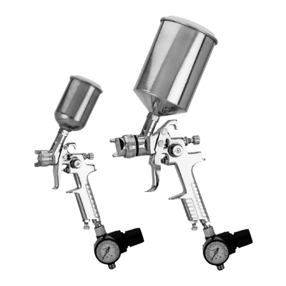
H7671
H7672
COPYRIGHT © JULY, 2005 BY GRIZZLY INDUSTRIAL, INC. REVISED FEBRUARY, 2008 (TR)
WARNING: NO PORTION OF THIS MANUAL MAY BE REPRODUCED IN ANY SHAPE
OR FORM WITHOUT THE WRITTEN APPROVAL OF GRIZZLY INDUSTRIAL, INC.
#PC7426 PRINTED IN CHINA
Advertisement
Table of Contents

Related Manuals for Grizzly H7671 H7672


Summary of Contents for Grizzly H7671 H7672
- Page 1 INSTRUCTION MANUAL H7671 H7672 COPYRIGHT © JULY, 2005 BY GRIZZLY INDUSTRIAL, INC. REVISED FEBRUARY, 2008 (TR) WARNING: NO PORTION OF THIS MANUAL MAY BE REPRODUCED IN ANY SHAPE OR FORM WITHOUT THE WRITTEN APPROVAL OF GRIZZLY INDUSTRIAL, INC. #PC7426 PRINTED IN CHINA...
-
Page 3: Table Of Contents
Table of Contents SECTION 1: SAFETY...4 Safety Instructions For Pneumatic Tools ...5 Additional Safety Instructions for HVLP Spray Guns ...6 SECTION 2: INTRODUCTION ...7 Foreword ...7 Contact Information ...7 Tool Data Sheet ...8 SECTION 3: SET UP...9 Inventory ...9 Assembly ...10 Controls ...10 SECTION 4: OPERATIONS ...11 Spraying ...11... -
Page 4: Section 1: Safety
SECTION 1: SAFETY For Your Own Safety Read Instruction Manual Before Operating This Equipment The purpose of safety symbols is to attract your attention to possible hazard- ous conditions. This manual uses a series of symbols and signal words which are intended to convey the level of importance of the safety messages. -
Page 5: Safety Instructions For Pneumatic Tools
Safety Instructions For Pneumatic Tools 10. USE PROPER AIR HOSE for the tool. Make sure your air hose is in good condition and is long enough to reach your work without stretching. 11. WEAR PROPER APPAREL. Do not wear loose clothing, gloves, neck- ties, rings, bracelets, or other jew- elry which may get caught in moving parts. -
Page 6: Additional Safety Instructions For Hvlp Spray Guns
Additional Safety Instructions for HVLP Spray READ THIS MANUAL. This manual contains proper operating instruc- tions for this spray gun. READ MATERIAL and MATERIAL SAFETY DATA SHEETS (MSDS). Read and know all the instructions on the packag- ing label and the MSDS before opening the package. -
Page 7: Section 2: Introduction
SECTION 2: INTRODUCTION Foreword We are proud to offer the Grizzly Model H7671/H7672 HVLP Spray Gun Set. These models are part of a growing Grizzly family of fine tools. When used according to the guidelines set forth in this manual, you can expect years of trouble-free, enjoyable operation, and proof of Grizzly’s commit-... -
Page 8: Tool Data Sheet
Customer Service #: (570) 546-9663 • To Order Call: (800) 523-4777 • Fax #: (800) 438-5901 HVLP SPRAY GUN SET MODEL MODEL CUP SIZE TYPE OF FEED FLUID TIP AIR CONSUMPTION INLET AIR PRESSURE LESS THAN FLUID PRESSURE CUP MATERIAL MAX. -
Page 9: Section 3: Set Up
SECTION 3: SET UP Inventory Your spray gun left our warehouse in a carefully packed box. If you discover the spray gun is damaged after you have signed for delivery, please immediately call Customer Service at (570) 546-9663 for advice. Save the containers and all packing materi- als for possible inspection by the carrier or its agent. -
Page 10: Assembly
Assembly Insert the filter into the gun body (see Figure 3). Figure 3. Installing filter. Screw the cup onto the top of the body. Attach the air hose to the spray gun with a ⁄ " NPS quick connect fitting (not included). -
Page 11: Section 4: Operations
SECTION 4: OPERATIONS EXPLOSION HAZARD! DO NOT smoke or have any source of flame or spark near spraying. Vapors will explode if ignited. RESPIRATORY HAZARD! Always use a NIOSH approved respirator when using spray equipment. Failure to protect your lungs can lead to respi- ratory illness and nervous system damage. - Page 12 7. Adjust the fluid control knob to start with a low volume of material and keep the atomization as low as possible. You will need to use a combination of fluid control, inlet air pressure, air flow control and stroke speed to achieve the results you want.
-
Page 13: Atomizing Cap And Fan Adjustments
Atomizing Cap and Fan Adjustments The atomizing cap needs to be adjusted for horizontal or vertical spraying patterns. Spraying in the wrong direction may lead to material build up on the atomizing cap horn. Many performance problems are caused by clogged atomizing holes on the atomizing cap horns (see Cleaning on Page 15). -
Page 14: Section 5: Accessories
SECTION 5: ACCESSORIES G6261—Campbell Hausfeld™ Water Filter Remove damaging water vapor before it reaches your pneumatic tools. This highly effective, five micron filter features a see- through bowl and easy in-line connections. 150 PSI maximum air pressure. Figure 10. G6261 Campbell Hausfeld™ water filter. -
Page 15: Section 6: Maintenance
SECTION 6: MAINTENANCE Cleaning Proper cleaning is the best way to ensure trouble free performance from your spray gun. If your gun is not thoroughly cleaned, damage and poor spraying will result. Problems caused by improper cleaning will not be covered by the warranty. Clean the spray gun immediately after each use. -
Page 16: Lubrication
Lubrication Figure 15. Lubrication points. Lubricate the following areas with a non- silicon spray gun lubricant after cleaning. A. Atomizing Cap Threads B. Air Valve Packing C. Trigger Pin D. Air Flow Control Valve E. Pattern Control F. Fluid Control Knob Allow the lubricant to coat threads, and run into gun body to lubricate all moving parts and seals. -
Page 17: Troubleshooting
Symptom Possible Cause Fluttering or spitting 1. Dry or worn fluid tip seat per- spray. mits air to seep into fluid pas- sage. 2. Material level too low. 3. Fluid tip or filter obstructed. 4. Dry needle packing. Uneven top or bot- 1. - Page 18 Symptom Possible Cause Excessive over- 1. Fluid pressure too high. spray. 2. Gun is too far from surface. 3. Spraying too fast. Unable to control 1. Pattern adjustment screw is spray fan. not seating properly. 2. Atomizing cap is loose. Runs and sags.
-
Page 19: Notes
Notes Model H7671/H7672 HVLP Spray Gun... -
Page 20: Parts Breakdown H7671-H7672
Parts Breakdown H7671/H7672 �� �� �� �� �� �� �� �� �� �� REF PART # DESCRIPTION PH7666001 VALVE COVER �� �� �� �� �� �� PH7666002 O-RING PH7666003 SWITCH SPRING PH7666004 SWITCH POLE PH7666005 SEAL WASHER PH7666006 O-RING PH7666007 FLUID KNOB PH7666008 NEEDLE SLEEVE... -
Page 21: Parts List H7671-H7672
Parts List H7671/H7672 REF PART # DESCRIPTION PH7671001 FLUID ADJUSTMENT SCREW PH7671002 FLUID ADJUSTMENT KNOB PH7671003 O-RING PH7671004 SPECIAL WASHER PH7671005 AIR VALVE SPRING PH7671006 AIR INLET VALVE PH7671007 SWITCH SPRING PH7671008 AIR INLET VALVE ASSY PH7671009 SWITCH KNOB PH7671010 SWITCH WASHER PH7671011 LOCK SCREW... -
Page 22: Warranty And Returns
WARRANTY AND RETURNS Grizzly Industrial, Inc. warrants every product it sells for a period of 1 year to the original purchaser from the date of purchase. This warranty does not apply to defects due directly or indirectly to misuse, abuse, negligence, accidents, repairs or alterations or lack of maintenance. - Page 23 ____20-29 ____50-59 How long have you been a woodworker/metalworker? ____0-2 Years How many of your machines or tools are Grizzly? ____0-2 Do you think your machine represents a good value? ____Yes Would you recommend Grizzly Industrial to a friend? ____Yes Would you allow us to use your name as a reference for our customers in your area? Note: We never use names more than 3 times.
- Page 24 Send a Grizzly Catalog to a friend: Name________________________________ Street________________________________ City______________State______Zip_______ FOLD ALONG DOTTED LINE GRIZZLY INDUSTRIAL, INC. P.O. BOX 2069 BELLINGHAM, WA 98227-2069 TAPE ALONG EDGES--PLEASE DO NOT STAPLE Place Stamp Here...