
Related Manuals for Alto OEX600


Summary of Contents for Alto OEX600
- Page 1 User's Manual OEX600 www.altoproaudio.com Version 1.1 May 2005 English English...
- Page 2 SAFETY RELATED SYMBOLS Fuse To prevent fire and damage to the product, use only the recommended fuse type as indicated in this manual. CAUTION Do not short-circuit the fuse holder. Before replacing the RISK OF ELECTRIC SHOCK DO NOT OPEN fuse, make sure that the product is OFF and discon- nected from the AC outlet.
-
Page 3: Table Of Contents
TABLE OF CONTENTS 1. INTRODUCTION ...........................3 2. FEATURES ............................3 3. QUICK START ............................5 4. CONTROL ELEMENTS ........................8 5. PRESET LIST............................12 6. OEX600 WIRING GUIDE ........................13 7. TECHNICAL SPECIFICATIONS ......................14 8. WARRANTY ............................16... -
Page 4: Introduction
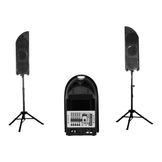
The L&R speaker cabinets are tightly hooked on the trolley. When you operate the OEX600, first of all take care of the setting of the L&R cabinets . It is the development of ALTO's experience and knowledge in speakers field, in order to faithfully reproduce sound for each kind of applications. - Page 5 In following picture you see OEX600 main components: High quality L&R full range speaker cabinets Powerful sub-woofer Versatile multi-channel mixer...
-
Page 6: Quick Start
3. QUICK START Though the OEX600 looks like a super formidable giant, you don't have to worry about how to carry it. As the OEX600 is equipped with two wheels, you can think of it as a trolley. Operating this unit, you will find out that it is really versatile and user-friendly. - Page 7 Now you can setup the system. Note: Make all initial connections with the system powered off, and, in order to avoid damaging your speakers and to have too much noise, with mixer main mix volume control completely turned down. Connect one side of the speaker cable to the left/right power outputs (1/4"TS jacks) of system, and the other side to the L/R speakers cabinet (1/4"TS jacks), as shown in Fig.5.
- Page 8 Finally, lay the speakers face down on top of the trolley and secure the six latches. Now the OEX600 is ready to be safely carried. The following figure(Fig.7) gives you a representation of connection / installation of your sound reinforcement system.
-
Page 9: Control Elements
4. CONTROL ELEMENTS (17) (23) (16) (11) (22) (12) (29) (10) (25) (13) (24) (14) (15) (27) (26) (28) (20) (21) (19) (18) - Page 10 (1). MIC IN These electronically balanced XLR sockets have been designed to accept microphone signals, providing low noise microphone pre-amplifier, as well as phantom power for condenser microphone when pushing ON the PHANTOM power switch. Note: You shall never connect an unbalanced microphone to the XLR socket if you don't want to damage both the microphone and mixer.
- Page 11 The stereo 12-segments LED meter indicates the signal level sent to CTRL ROOM and PHONES outputs. (16). PWR LED Display It indicates the OEX600 is powered on. (17). MAIN MIX LEVEL Dial Rotating this dial you will to adjust the overall volume of the left and right main mix outputs. The adjustable range is from - to +15dB.
- Page 12 (32) (30). AC INLET with FUSE HOLDER This standard IEC receptacle is supplied to allow to connect your OEX600 to mains via the supplied power cord. (31). POWER Switch It switches on/off the OEX600 main power. (32). Powered Output Connectors...
-
Page 13: Preset List
5. PRESET LIST Description parameter Preset Rev. Decay time: 360ms WARM HALL Simulate a small acoustic space of the sound. Pre-delay: 45ms Rev. decay time: 290ms Simulate a large acoustic space of the sound. BRIGHT HALL Pre-delay: 23ms Rev. decay time: 210ms Simulate a small acoustic space of the sound. -
Page 14: Oex600 Wiring Guide
6. OEX600 WIRING GUIDE Defective wiring may degrade the performance of OEX600 so, please, use good quality screened audio cables only. Please follows the descriptions below to interface OEX600 without experiencing and noise or signal lose. Input/Output Diagram Model Type... -
Page 15: Technical Specifications
7. TECHNICAL SPECIFICATIONS Mixer Section Mono input channels Microphone Input Electronically balanced, discrete input configuration Frequency response 10Hz to 55kHz,+/- 3dB Distortion(THD&N) 0.04% at +4dBu,1kHz Gain 35dB SNR(Signal to Noise Ratio) >94dB Line input Electronically balanced Frequency response 10Hz to 55kHz,+/- 3dB Distortion(THD&N) 0.04% at +4dBu,1kHz Gain... - Page 16 Speaker Section 3-Way Powered System Bi-Amp plus passive crossover into Satellite Low Output Power 150W RMS Class AB MID-HIGH Output Power 75W+75W RMS Class AB Peak Power Rating 600W Peak Max SPL at 1mt 116.5dB Continuous - 119.5dB Peak ( calculated ) Frequency response 55Hz- 20kHz @ -10dB Impedance Low-Mid/High...
-
Page 17: Warranty
8. WARRANTY 7.1 WARRANTY REGISTRATION CARD To obtain Warranty Service, the buyer should first fill out and return the enclosed Warranty Registration Card within 10 days of the Purchase Date. All the information presented in this Warranty Registration Card gives the manufacturer a better understanding of the sales status, so as to purport a more effective and efficient after-sales warranty service. - Page 18 No.1, Lane 17, Sec. 2, Han Shi West Road, Taichung, 401 TAIWAN http://www.altoproaudio.com Tel:886-4-22313737 email: alto@altoproaudio.com Fax:886-4-22346757 All rights reserved to ALTO. All features and content might be changed without prior notice. Any photocopy, translation, or reproduction of part of this manual without written permission is forbidden. Copyright 2004 Sekaku Electron...