Table of Contents
Advertisement
Quick Links
Download this manual
See also:
Instruction Manual
Advertisement
Table of Contents

Related Manuals for Datavideo SE-600


Summary of Contents for Datavideo SE-600
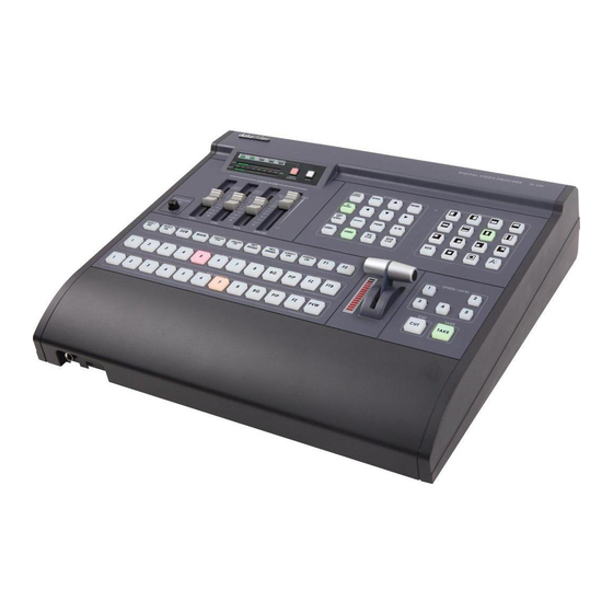
- Page 1 Digital Video Switcher SE-600 Quick Start Guide www.datavideo-tek.com...
-
Page 2: Table Of Contents
Table of Contents Warnings & Precautions ....................... 2 What’s in the box? ........................3 Introduction ..........................3 Features ............................3 Connections & Controls ........................ 5 Front Panel ........................... 5 Audio Inputs and Levels ......................10 Rear Panel ..........................12 Effects ............................14 Dimension .......................... -
Page 3: Warnings & Precautions
7. This product should only be operated from the type of power source indicated on the marking label of the AC adapter. If you are not sure of the type of power available, consult your Datavideo dealer or your local power company. -
Page 4: What's In The Box
To fulfil and give a more cost effective with excellent features, Datavideo provides an eight inputs SD switcher. 6 Composite video + 2 DVI-D input with 2 PIP, Luma key and DV out. -
Page 5: Audio Mixer
Video: 6 composite video + 2 DVI-D Output Preview out: DVI-D for Multi-Viewer with clock and audio level indicator (Multi-viewer output same quality as SE-900 new multi-viewer board) Main out: CVBS x 3 (recorder/ program out/ streaming) ... -
Page 6: Connections & Controls
Connections & Controls Front Panel 1. Main / Sub Source 7. Effects 2. AUX Source 8. Transition 3. Headphone Volume Control 9. Speed/ Level 4. Audio Mixer 10. Cut & Take 5. Audio Meters 11. T-Bar 6. Special Effects... - Page 7 MAIN SOURCE Used to select which of the four video input channels or background is sent to the Main video output. For more information, see Video Source(Page 10). SUB SOURCE Used to select which of the four video input channels or background will be transitioned to or used as a sub source in an effect.
- Page 8 AUDIO METERS LED style meters, which show the signal strength at the Audio Output. The signal they measure is determined by the sources selected by the Audio Bus selectors and the levels set by the Faders. These meters show the audio signal level at the Main output. The strength of any audio signal that is routed to the output will be displayed here.
- Page 9 EFFECTS Menu button is SE-600 functions configuration and setting, press the up, down, left, right arrow button move to another control, and ENTER button to confirm the setting. LOGO SETTING / PIP SETTING / LUMA KEY SETTING These three buttons is swift button, let you can setting these function instantly.
- Page 10 Speed / Level Selectable of five different speeds or level for transition effect. Change the main/sub source immediately. TAKE Take the effect by preset speed. T-Bar The T-Bar is used to carry out a manual transition such as a wipe, fade, mix or key.
-
Page 11: Audio Inputs And Levels
Video Source Selecting the Main and Sub Video Sources is the first thing to do when setting up the SE-600. The source you select (by pressing one of the buttons; a bright red LED on the selected button lights for confirmation) on the Main Source bus is what is sent to the Video output. -
Page 12: Transition Effects
Transition Effects Left to Right Right to Left Bottom to Up Top to Bottom Middle extend Inside Out (U/D) Middle extend Outside In (U/D) Middle extend Inside Out (L/R) Middle extend Outside In (L/R) Left High to Right Down Right Down to Left High Left Down to Right High Right High to Left Down Add a border to certain effects such as Wipes. -
Page 13: Rear Panel
Rear Panel 1. DVI Input 7. RS-422 2. CV Input 8. Power 3. CV Output 9. DC In 4. Multi View 10. Audio Output 5. Tally 11. Audio Input 6. GPI DVI-D Input DVI-D digital signal input connecter. DVI-I digital signal input connecter. CV Input Composite video input: takes a BNC connector from the composite output of a VCR, camera, DVD player, etc. - Page 14 Multi View DVI-D digital signal preview output connecter. TALLY Tally out socket. This supplies tally light information up to eight buttons of main source, and other eight button of sub source. The GPI socket can be used for simple external control. RS-422 9-pin serial port standard RS-4 22 interface.
-
Page 15: Effects
3: CG (LUMA KEY) 4: LOGO 5: VIDEO IN & OUT 6: AUDIO MIXER 7: MULTI. IMAGE 8: SYSTEM 9: STORE RECALL & UPDATE 10: RESET DVI_IN ESCAPE After SE-600 firmware upgrade, you need to reload your (logo, background, name…etc) files to SE-600. - Page 16 2: PIP Press the SETTING button and then press arrows button to select PIP item. Press the ENTER to confirm the setting PIP Source - select PIP source (CH_1~CH_8) PIP Size - select PIP size (big or small) ...
- Page 17 3: CG (LUMA KEY) Press the SETTING button and then press arrows button to select CG (LUMA KEY) item Press the ENTER to confirm the setting SOURCE - select CG source channel (CH_1~CH_8 or BG) KEY LEVEL MAX. - adjustment range from 20 to 255 ...
- Page 18 4: LOGO Press the SETTING button and then press arrows button to select LOGO item Press the ENTER to confirm the setting SOURCE - select LOGO source channel (CH1~CH8, BG or LOGO FILE) LOGO POSITION - adjustment position (X:1~147;Y:1~119) ...
- Page 19 5: VIDEO IN & OUT Press the SETTING button and then press arrows button to select VIDEO IN & OUT item Press the ENTER to confirm the setting VIDEO CH. - select video Channel (IN_1~IN_8) INPUT _TYPE - select input type (CV) ...
- Page 20 6: AUDIO MIXER Press the SETTING button and then press arrows button to select AUDIO MIXER item Press the ENTER to confirm the setting TONE_OUT - select ON or OFF TONE_LEVEL - adjustment range from 20 to -40 ...
- Page 21 7: MULTI. IMAGE Press the SETTING button and then press arrows button to select MULTI. IMAGE item Press the ENTER to confirm the setting OUTPUT TYPE - BORDER BRIGHT - adjustment range from 001 to 100 CAM1~8_NAME - CAM1~8 channel name setting ...
- Page 22 8: SYSTEM Press the SETTING button and then press arrows button to select SYSTEM item Press the ENTER to confirm the setting GPI SETTING - SPEED KEY SETTING - adjustment range from 2 to 90 SWITCH BRIGHTNESS - adjustment switch brightness ...
- Page 23 9: STORE RECALL & UPDATE Press the SETTING button and then press arrows button to select SYSTEM item Press the ENTER to confirm the setting STORE & RECALL - UPDATE - select update mode RESET ALL – reset all PCB firmware ...
- Page 24 10: RESET DVI_IN Press the SETTING button and then press arrows button to select RESET DVI_IN item Press the key or can reset DVI_1/2 IN 1: COUNT_DOWN_TIME 2: PIP 3: CG (LUMA KEY) 4: LOGO 5: VIDEO IN & OUT 6: AUDIO MIXER 7: MULTI.
-
Page 25: Dimension
Dimension... -
Page 26: Specification
Specification ˙Composite Video * 6 ˙DVI-D * 1 Video Inputs ˙DVI-I * 1 ˙Main out: CVBS *2(recorder/program out/streaming),Y/C or YUV *1 ˙Aux (1)out: CVBS * 2 Outputs ˙Aux (2)out: CVBS * 2 ˙DV Out: 1394 * 2(Optional), SDI * 2 (Optional) 0/7.5 IRE Options (NTSC only) ˙Wipe and dissolve ˙PIP: 2 of PIP effects... -
Page 27: Service & Support
It is our goal to make your products ownership a satisfying experience. Our supporting staff is available to assist you in setting up and operating your system. Please refer to our web site www.datavideo-tek.com for answers to common questions, support requests or contact your local office below.