Splendide WD2100XC Training Manual
Front-loading automatic washer-dryer
Hide thumbs
Also See for WD2100XC:
- Instructions for use manual (24 pages) ,
- Specifications (2 pages) ,
- Quick operation manual (2 pages)

Related Manuals for Splendide WD2100XC


Summary of Contents for Splendide WD2100XC
- Page 1 T E C H N I C A L E D U C AT I O N G R O U P P R E S E N T S WD2100XC / XCP (Splendide 2100XC) WDC7100XCP (Splendide 7100XC) Front-Loading Automatic Washer-Dryer Training Guide Part No.
- Page 2 C o n t a c t I n f o Product Specifications & Warranty Info Westland Sales, Splendide Tech Dept. 1-800-356-0766 EXT. 5 (503-655-2563) Technical Assistance & Parts Ordering Westland Sales, Splendide Tech Dept. 1-800-356-0766 EXT. 5 (503-655-2563) Literature Orders Westland Sales, Splendide Tech Dept.
- Page 3 Splendide washer- dryer models WD2100XC and WDC7100XC. It is to be used as a supplemental training aid for service technicians. For more information on the washer-dryer, refer to the “Use and Care Guide” provided with the appliance.
-
Page 5: Table Of Contents
C o n t e n t s 1. General Information Model / Serial Number Designators Warranty Guide Washer-Dryer Specifi cations IMPORTANT General Safety Information 2. Installation Information Installation Requirements Installation Instructions 3. Theory of Operation Introduction to the Models Water System Wash/Dry System Door Lock / Switch Assembly... - Page 6 5. Component Testing Procedures Connector Locations on the Module Board Introduction / Instructions 1. Door Switch Test 2. Power “in” from the Surge Protector Test 3. Pressure Switch Test 4. Heating Element Test 5. Main Motor Test (Includes Running the Main Motor with AC Voltage) 6.
-
Page 7: General Information
G e n e r a l I n f o r m a t i o n Model / Serial No. Designators Use these numbers to obtain the Warranty status as well as a history of repairs and service calls for the washer-dryer. To speed the repair process, ALWAYS have the Model and Serial No. -
Page 8: Warranty Guide
Warranty Guide* Refer to this page for a brief summary of the Product Warranties available by Splendide. Wty Length Splendide Will Pay For Splendide WILL NOT Pay For A. Repairs when the washer-dryer is used in other MFR 1-YEAR Replacement parts ONLY. -
Page 9: Washer-Dryer Specifi Cations
Washer-Dryer Specifications The following is a list of product specifi cations for the Splendide Models covered in this Training Guide. Model Number WD2100XC / WD2100XCP WDC7100XCP COLOR White Platinum DRYER TYPE Vented Ventless ELECTRICAL REQ. Max. Current Rated Current 15 A... -
Page 10: Important General Safety Information
IMPORTANT General Safety Information Your safety is important. Read this section before you continue. Important safety messages can be found in this manual and on WARNING the appliance. Always read and obey all safety messages. This is a safety alert symbol. This symbol ELECTRICAL SHOCK HAZARD alerts you to potential hazards that can kill or Plug washer-dryer into a... -
Page 11: Installation Information
RV or boat water damage Splendide Drain-A-Way Pan, or equivalent. concerns to make a 90” duct Splendide 90˚ offset elbow, or equivalent. turn in less than 4.5” Location • This machine may be installed free standing as well as in a recessed area, closet, or alcove •... - Page 12 Washer-Dryer Dimensions Undercounter Install Requirements The dimensions shown are for the minimum spacing allowed. 0 in. (0 cm) 33-1/4 in. (84.5 cm) 0 in. 23-1/2 in. 0 in. (0 cm) (59.7 cm) (0 cm) Recessed Area/Closet Install Requirements The dimensions shown are for the minimum spacing allowed. Additional spacing should be considered for: •...
- Page 13 Floor Standpipe w/ "Y" Branch Tail Piece A & B = 25" (62 cm) min. / 34" (86 cm) max. Optional • The Splendide Faucet Adapter Kit, Part No. The standpipe drain requires a minimum diameter standpipe of 154187104A 1-1/4” (3.2 cm). The minimum carry-away capacity can be no less •...
-
Page 14: Electrical Requirements
Electrical Requirements WARNING GROUNDING INSTRUCTIONS ELECTRICAL SHOCK HAZARD Plug washer-dryer into a This appliance must be grounded. In the event of a malfunc- grounded 3 prong outlet. tion, or breakdown, grounding will reduce the risk of electric Do not remove ground prong. shock by providing a path of least resistance for electric current. -
Page 15: Installation Instructions
Installation Instructions Follow these instructions in order to prevent installation errors and to assure proper washer-dryer operation. Unpacking the washer-dryer Connecting the water inlets • Carefully remove the packing materials with care If the water pipes you will be connecting to are not to damage the drain hose and power cord new or unused, run the water until clear to remove that are shipped installed on the machine. -
Page 16: Connecting The Drain Hose
Connecting the drain hose the fl oor to a separate trap. The trap must be vented It is possible for the water to be discharged into a sink, to prevent siphoning. To provide proper venting, install standpipe or drainpipe, but an air break must be available an Air Gap Kit (available at most hardware stores). - Page 17 fl ange vent located on the back of the machine (Fig. 8). WD2100XC WARNING! -To reduce the risk of fi re, this appliance must be exhausted to the outdoors. Rigid or fl exible metallic duct required. Ducting must be as short and straight as possible.
-
Page 18: Completing The Installation
When installing this appliance in an RV or marine vessel, you should block in the unit to prevent it from shifting or tipping. A SecureFit Bracket Kit is available from Splendide to keep the unit from shifting front-to-back or side-to- side. -
Page 19: Theory Of Operation
T h e o r y o f O p e r a t i o n Introduction The Splendide Front-Loading Washer-Dryer models present many new features and characteristics that are diff erent from previous models. In addition to the introduction of electronic controls, the washer- dryer contains a number of unique operating features designed to off... -
Page 20: Pressure Switch
Pressure Switch The pressure switch is located in the top, right-front corner of the washer. This switch senses the water level in the drum. The control signal from the pressure switch is sent to the Module Board and is used to determine the amount of water introduced into the drum during the wash cycle. -
Page 21: Wash/Dry System
Wash/Dry System The Wash/Dry System consists of the Module Board, the Main Motor, the Pump Motor and the Dryer Heating Element. Module Board The Module Board is located at the bottom, right-rear corner of the washer-dryer. If diagnostic tests indicate that the module board is defective, the entire module board must be replaced. - Page 22 Module Board provides power to the element in the dry cycle. During the dry cycle: • Vented model (WD2100XC) take air from the surrounding room, heat it, tumble it through the clothes, and then exhaust it to the outside through a vent.
-
Page 23: Door Lock/Switch Assembly
Door Lock/Switch Assembly The Door Lock/Switch Assembly is located on the right side of the door opening. The assembly contains a solinoid operated latching mechanism that will electrically lock the door during a wash or dry cycle. Door Lock/Switch Assembly Suspension System The drum assembly is held in position with two shock absorbers attached to the bottom sides of the tub assembly. -
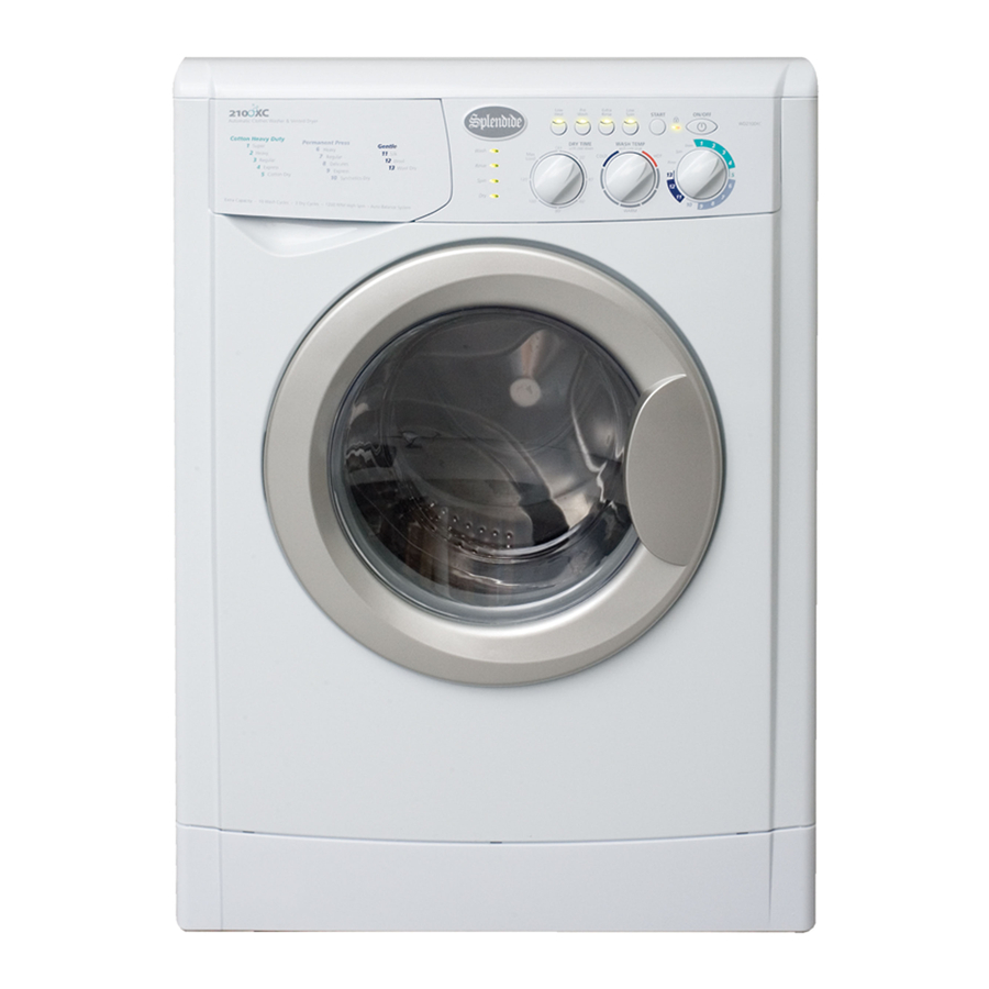
Page 24: Customer Interface / Cycle Selection System
Customer Interface / Cycle Selection System The Customer Interface / Cycle Selection System consists of the Control Panel/LED Assembly along with the program timer, option buttons, and Wash Temperature and Dry Time Selectors. Control Panel/LED Assembly The Control Panel/LED Assembly (Fig. 3-3) is removed as a single assembly and is connected to the Module Board by 5 connection points to the wiring harness. - Page 25 Description of Control Panel Buttons, Knobs & LED’s ON/OFF Button- Use the ON/OFF Button to turn machine power ON or OFF START Button- Use this button to START a cycle (press once) or RESET the controls (press and hold for 5 seconds).
- Page 26 Resetting the Controls Clearing the controls - Pushing and HOLDING the START button for 5 seconds will cancel the current program and allow you to set a new one. Cancelling a cycle in progress and setting a new cycle - Use the START button to cancel a program in progress and start a new cycle: 1.
- Page 27 Description of Preset Wash Cycles Cotton Heavy Duty Wash - Use the Cotton Heavy Duty cycles to wash loads of sturdy, colorfast fabrics and normally to heavily soiled garments. These cycles combine fast speed tumbling and an extra high spin speed (1200 RPM) to shorten dry times. •...
- Page 28 Description of Preset Dry Cycles Cotton Dry - Use this high heat cycle to dry sturdy, colorfast fabrics like towels socks and jeans. There’s a high spin at the beginning of this cycle to remove more water from fabrics. Synthetics Dry - Use this medium heat cycle to dry certain blouses and casual business clothes. Wool Dry - Use this high heat dry cycle to dry wool items ONLY.
- Page 29 Preset Wash/Dry Cycles Chart*** Program Knob Detergent Degree of Cycle Fabric Special Cycle Type of fabric soil Name Wash Wash Softener Bleach Programs Length Cycle Description Cotton Heavy Duty Cycles Low Heat Exceptionally Super • • • Extra Rinse 96 min. Wash cycle, rinse Soiled Low Spin...
-
Page 30: Automatic Routines
Automatic Routines The following are routines that the washer-dryer will follow out automatically during all of the wash, spin, rinse and dry cycles. Door Locking / Unlocking Routines Door Locking Summary - The Door Locking Routine will only start if the door is securely closed and the Door Switch contact is CLOSED. - Page 31 Wash Quality Routines Drain and Spin Routines - During the Drain and Spin cycles, the water level is checked continuously. Normal Drain and Spin will occur until the Pressure Switch senses no water or foam (suds) in the drum. Foam Detection and Elimination Routine - Excessive foam can make clothes appear dingy and is usually caused by the use of too much detergent, or the wrong kind of detergent.
- Page 32 N O T E S :...
-
Page 33: Accessing The Components
A c c e s s i n g t h e C o m p o n e n t s Component Locations Follow the instructions in this section to gain access the following components. (DRY NTC) Accessing the Components... -
Page 34: Top Panel / Control Panel Knobs
Required Tools To access components in this washer-dryer, you’ll need Metric and Standard sockets of various sizes, Torx-15, 25 Drivers, a Flat Head screwdriver, and a Phillips Head screwdriver. Top Panel / Control Panel Components Access to the Control Panel requires that the top of the washer be removed. Removing the Knobs Removing the Washer-Dryer Top Remove the knob by pulling straight out. -
Page 35: Control Panel Board / Control Panel
Removing the Control Panel Board Removing the Control Panel Remove the wire connector from the panel board (Fig. 4-2). Remove the three Phillips Head Screws (Fig. 4-4) located Remove the two Phillips screws that secure the panel board behind the Dispenser Drawer to the control panel (Fig. -
Page 36: Door / Door Switch / Porthole Diaphragm
Door / Door Switch / Porthole Diaphragm Open the Door to access the Door, Door Switch and Porthole Diaphragm. Removing the Door panel. (See “Removing the Porthole Diaphragm” to remove the Remove the two, size 15 Torx entire diaphragm.) The door switch is secured to the washer screws that secure the door front panel with two, size 15 Torx screws. -
Page 37: Detergent Dispenser Assembly / Water Valves
Detergent Dispenser Assembly / Water Valves Access to the Detergent Dispenser and Water Valves requires that the top of the washer be removed. Loop Removing the Dispenser Assembly Begin by removing the top, then use two hands to pull the Disconnect the dispenser hose from dispenser drawer completely out of the housing. -
Page 38: Pressure Switch
IMPORTANT! It’s very important to note the orientation of the wiring on the valves for re-installation. If the wiring is switched the water temperatures will be incorrect, and on condenser machines, the dry cycle will not operate correctly. Pressure Switch The Pressure Switch is located on the top-right, front corner of the machine. -
Page 39: Fan Motor / Ntc Sensor / Heater Coil
Fan Motor, NTC Sensor and Heater Coil The Fan Motor, NTC Sensor, Heater Coil and Housing sit on the drum and are located on the top, right side of the machine. It can be accessed once the top is removed. Removing the Fan Motor Disconnect the two wires that are attached to the fan motor and Remove the 10mm nut with LEFT-HANDED threads (Below) that... -
Page 40: Removing The Heater Coil
Removing the Heater Coil Remove the two wires from the heater coil and lift the heater coil out of the heater housing. Fig. 4-20 Heater Coil Accessing the Components... -
Page 41: Lower Panel / Drain Pump / Pump Filter
Lower Panel / Drain Pump / Pump Filter The Drain Pump is located at the lower, right-corner of the machine. You’ll need to remove the Lower Panel to access the Drain Pump and Pump Filter. Removing the Drain Pump Removing the Lower Panel With the Lower Panel removed and any residual water drained Gently ease down the top of the panel with a fl... -
Page 42: To Clean Out The Large Item Filter
Before you disconnect the hoses, note their orientation and place a towel under them to catch any water left inside. Unclamp the hoses from the drain pump and remove the pump assembly. (Fig. To Clean Out the Large Item 4-24) Filter To clean out the Large Item Filter, turn the large knob counterclockwise and pull it out. -
Page 43: Back Panel / Main Motor / Module Board
Back Panel / Main Motor / Module Board The Main Motor and Module Board can be accessed once the back panel has been removed. Removing the Back Panel Removing the Module Board Remove the 7 Phillips screws that secure the panel to the back Remove the two, size 15 Torx Head screws that secure the of the cabinet. -
Page 44: Shock Absorbers
Shock Absorbers The Shock Absorbers can be accessed once the bottom panel has been removed. Removing the Bottom Panel Removing the Shock Absorbers The tub is held in position by two shock absorbers. To access the Remove the bolts that secure the shock absorbers to the tub Shock Absorbers, First, place the washer-dryer on its left side. -
Page 45: Component Testing Procedures
C o m p o n e n t T e s t i n g P r o c e d u r e s Connector Locations on the Module Board The following tests are performed by taking ohm readings on the Module Board connections listed below. The Module Board can be accessed once the back panel has been removed. -
Page 46: Introduction / Instructions
• Make sure that the power cord is fi rmly plugged into a live circuit with the proper voltage. • Check for a blown household fuse or circuit breaker that has tripped. • Make sure that the dryer vent is properly installed and clear of lint obstructions. (WD2100XC Only.) When testing, follow these instructions: •... -
Page 47: Door Switch Test
1. Door Switch Testing Door Switch Test Points are located on the connector on the Module Board and on the Door Switch (See “Connector Locations on the Module Board”) J4 on Module Board Door Switch Fault Codes: F17 Test Points Reading Door Switch to J4 3 to 3... -
Page 48: Power "In" From The Surge Protector Test
2. Power “in” from the Surge Protector Test Surge Protector Test Points are located on both the Surge Protector and on the J1 Connector. The Surge protector is connected to the Module Board (See “Connector Locations on the Module Board”). The J1 Connector is on the Module Board (See “Connector Locations on the Module Board”) J1 on Module Board Surge... -
Page 49: Pressure Switch Test
3. Pressure Switch Test Pressure Switch Test Points are located on both the J3 Connector and on the Pressure Switch. The J3 Connector is on the Module Board (See “Connector Locations on the Module Board”). The Pressure Switch can be accessed once the top is removed (See “Component Access Locations”) J3 on the Module Board Fault Codes: F04, F05, F07, F08, F10, F15... -
Page 50: Heating Element Test
4. Heating Element Test Heating Element Test Points are located on the J2 Connector on the Module Board (See “Connector Locations on the Module Board”) J2 on the Module Board Fault Codes: F17 Test Points Reading J2 Connector 1 to 2 11 ohms Component Testing Procedures... -
Page 51: Main Motor Test (Includes Running The Main Motor With Ac Voltage)
5. Main Motor and Water Pump Test Main Motor Test Points are located on the J9 Connector on the Module Board (See “Connector Locations on the Module Board”). J9 on the Module Board 9 8 7 6 5 4 3 2 1 Fault Codes: F11 Test Points Reading... -
Page 52: Fan Motor / Water Pump Test
6. Fan Motor Test / Water Valve for WDC7100XC Test Fan Motor Test Points are located on the J16 connector on the Module Board (See “Connector Locations on the Module Board”) J16 on the Module Board Fault Codes: N/A Test Points Reading J16 Connector (Fan Motor) 1 to 2... -
Page 53: Water Valve / Wash Ntc Test
7. Water Valve Test / Wash NTC Test Water Valve Test Points are located on the J8 Connector on the Module Board (See “Connector Locations on the Module Board”) J8 on Module Board 1 3 4 6 7 9 11 12 Fault Codes: F3 (Wash NTC) Test Points Reading... -
Page 54: Control Panel Board Test
8. Control Panel Board Test Control Panel Board test points are located on the control panel board and the J11 connector o the Module Board (See “Connector Locations on the Module Board”) J11 on Module Board 54321 J11 on Module Board Fault Codes: F12 Test Points Reading... -
Page 55: Dry Ntc Sensor Test
9. Dry NTC Sensor Test NTC Sensor Test Points are locted on the J10 Connector on the Module Board J10 on the Module Board Fault Codes: F13 Test Points Reading J10 Connector 4 to 5 27K@65˚F Component Testing Procedures... -
Page 56: Diagnosis & Troubleshooting
D i a g n o s i s & T r o u b l e s h o o t i n g Introduction This section includes an Explanation of the Fault Codes for models WD2100XC and WDC7100XC as well as a Fault Code/Testing Procedure Chart and a Problem/Testing Procedure Chart. -
Page 57: Explanation Of Fault Codes
Explanation of Fault Codes These appliances incorporate an onboard diagnostic system to help you troubleshoot any problems that you may encounter. (See Chart on next page.) When the machine is in the Fault Mode, • The DOOR LOCK LED will fl ash quickly (frequency > 1 Hz, fl ashes more than one time per second) •... -
Page 58: Fault Code / Testing Procedure Chart
Fault Code / Testing Procedure Chart See “Explanation of the Fault Codes” on the previous page to determine the Fault Code that the washer-dryer is displaying. Then, follow the recommended DISPLAY testing procedure to troubleshoot the problem. Call Westland Sales if the machine continues displaying the Fault Code. Fault Code Explanation / Recommended Testing Procedure Short-circuited Motor TRIAC on Module Board... - Page 59 Fault Code Explanation / Recommended Testing Procedure File Set-Up Error (Unverifi able Fault) Missing or Confl icting Pressure Switch Signal • Verify Pressure Switch connections and wiring. See “Component Testing”. Drain Pump Power Supply Failure • Verify Drain Pump connections and wiring, See “Component Testing”. Communication Failure •...
-
Page 60: Problem / Testing Procedure Chart
Problem / Testing Procedure Chart Follow these steps in the order they are listed to eff ectively troubleshoot the problem. DISPLAY Call Westland Sales if the problem continues after you have completed the recommended tests. Problem Testing Procedure WON’T POWER UP 1. - Page 61 Problem Possible Cause / Recommended Testing DRUM WON’T ROTATE 1. Remove the washer-dryer back and check the Drive Belt. 2. Check the Main Motor. 3. Check the Wire Harness connections. WON’T DRAIN 1. Remove the washer-dryer back and check the Drain Pump 2.
-
Page 62: Tech Tips
8. Release the Door Switch by pressing and holding the START button. If you test a model WD2100XC and the Airfl ow and Heat Test results are normal but the problem persists, check the dryer exhaust system for obstructions: •... -
Page 63: Winterization Instructions / Optional Rv Winterization
SPECIAL WINTERIZATION INSTRUCTIONS FOR RV/MARINE INSTALLATIONS : To winterize washer-dryer, To use washer-dryer again, With washer-dryer power Reconnect water inlet hoses OFF, pour ½ quart of RV-type to corresponding HOT/COLD antifreeze into washer drum; faucets. Turn faucets ON. NOTE: Check water inlet hoses Close door. -
Page 64: Verifying Normal Operation
The following instructions explain how to test the washer-dryer to make sure everything’s working properly. Keep in mind, this appliance operates diff erently than some of the previous Splendide models you may be familiar with. It’s important to note the following diff erences: •... -
Page 65: Wiring Diagrams
W i r i n g D i a g r a m s WD2100XC / WD2100XCP / WD7100XCP OVERFLOWW COMUNE PIENO VUOTO Wiring Diagrams... - Page 66 WD2100XC / WD2100XCP / WD7100XCP BROWN 1000 MODULE BLUE 1000 BOARD BLUE 3-P11 1250 4-P16 1-J3 PRESSURE BROWN 1250 2-P14 SWITCH 3-J3 BLUE 1250 4-J3 1-P12 A = WIRING ASSEMBLY MODULE - BOARD - SURGE PROTECTOR - PRESSURE SWITCH LIGHT BLUE...
-
Page 67: Wiring Diagrams
WD2100XC / WD2100XCP / WD7100XCP 1640 BROWN DIC4 WHITE MODULE 1640 DIC3 1640 DIC2 D1 = WIRING ASSEMBLY MODULE - DOOR INTERLOCK BLACK BLACK MODULE BLACK RST 5 BLACK BLACK L = WIRING ASSEMBLY MODULE - DRAIN PUMPE - WASH MOTO... - Page 68 Splendide ® © C o p y r i g h t 2 0 0 7 , W e s t l a n d S a l e s , C l a c k a m a s , O R 9 7 0 1 5...