Table of Contents
Advertisement
Advertisement
Table of Contents

Related Manuals for Jet JWBS-14DXPRO


Summary of Contents for Jet JWBS-14DXPRO
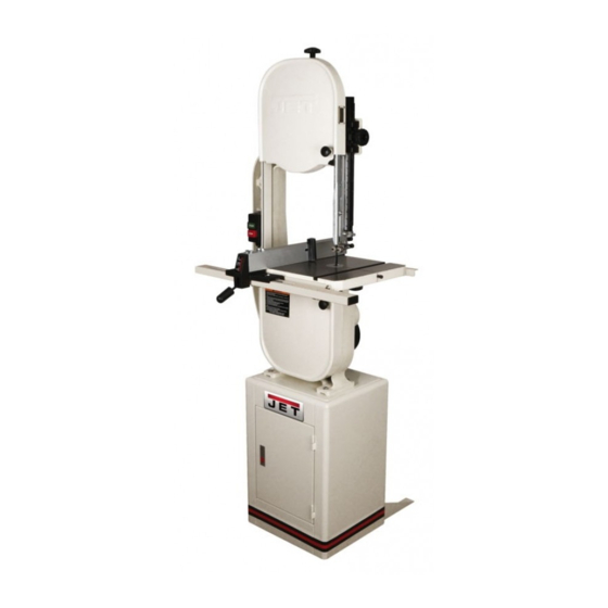
- Page 1 This .pdf document is bookmarked Operating Instructions and Parts Manual 14-inch Deluxe Pro Band Saw Models: JWBS-14DXPRO (Shown with optional Rip Fence) 427 New Sanford Road LaVergne, Tennessee 37086 Part No. M-710116 Ph.: 800-274-6848 Revision D 02/2017 www.jettools.com Copyright © 2017 JET...
-
Page 2: Warranty And Service
Accessories; Shop Tools; Warehouse & Dock products; Hand Tools; Air Tools NOTE: JET is a division of JPW Industries, Inc. References in this document to JET also apply to JPW Industries, Inc., or any of its successors in interest to the JET brand. -
Page 3: Table Of Contents
Troubleshooting ............................... 18 Parts ..................................18 Body Assembly (JWBS-14DXPRO) ........................19 Body Assembly (JWBS-14DXPRO) ........................20 Closed Stand Assembly (JWBS-14DXPRO) ....................... 24 Closed Stand Assembly (JWBS14-DXPRO) ....................... 25 Electrical Schematic – 115V ..........................26 Electrical Schematic – 230V ..........................27... - Page 4 5. Do not use this band saw for other than its intended use. If used for other purposes, JET disclaims any real or implied warranty and holds itself harmless from any injury that may result from that use.
- Page 5 25. Use the right tool at the correct speed and feed rate. Do not force a tool or attachment to do a job for which it was not designed. The right tool will do the job better and safer. 26. Use recommended accessories; improper accessories may be hazardous. 27.
- Page 6 Shipping Weight (approx.) ..........................258 lb. The specifications in this manual are given as general information and are not binding. JET reserves the right to effect, at any time and without prior notice, alterations to parts, fittings, and accessory equipment deemed...
-
Page 7: Shipping Contents
Warranty card Tools Required for Assembly (2) 10mm and (2)13mm open end wrenches or adjustable wrenches Fasteners for JWBS-14DXPRO 1 – M6x16 carriage bolt (4) 2 – M6x8 pan head screw (1) 3 – M6 hex nut (4) 4 – M8 lock washer (6) 5 –... -
Page 8: Assembly
3. With the aid of a second person, lift the saw body out of the shipping container and place Figure 1 onto stand top. Be sure front of saw (with JET logo) faces stand front (Door Side). 4. Line up holes in saw body with holes in the top of the stand. -
Page 9: Mounting The Trunnion Bracket To The Band Saw
Mounting the Trunnion Bracket to the Band Saw 1. Attach trunnion support to saw body with two M8 x 40 hex cap screws and two M8 lock washers. See Figure 2. 2. Thread nut on to table stop bolt (Fig. 2) and attach to trunnion support bracket as shown. -
Page 10: Grounding Instructions
21, if a properly grounded outlet is not available. The Grounding Instructions temporary adapter should only be used until a properly grounded outlet can be installed by a This Band must qualified electrician. This adapter is not applicable in grounded while in use to protect the operator Canada. -
Page 11: Extension Cords
230V operation, as shown in Figure 23. The smaller the gauge number, the heavier the cord. Contact your local authorized JET service center or Repair or replace a damaged or worn cord qualified electrician for proper procedures to install immediately. -
Page 12: Adjustments
Adjustments Tilting the Table Unplug the machine from the power source before making any repair or adjustment! Failure to comply may cause serious injury! 1. Loosen two lock knobs (Fig. 4). 2. Tilt table up to 45 degrees to the right or down 10 degrees to the left, using the scale mounted to the trunnion. -
Page 13: Changing Blades
Changing Blades Blade teeth are sharp! Use care when handling the saw blade. Failure to comply may cause serious injury! 1. Disconnect machine from power source. 2. Loosen blade tension by pushing up on the release lever (Fig. 6). 3. Remove the table insert and the table pin. 4. -
Page 14: Adjusting Blade Tension
Adjusting Blade Tension 1. Disconnect machine from power source. 2. Make sure the blade is tensioned with the release lever in the down position as seen in Fig. 7. 3. Turn blade tension knob (Fig. 6) clockwise to tension blade. The blade width gauge (D, Fig. 8) indicates the approximate tension according to the width of the blade. -
Page 15: Adjusting Blade Tracking
Adjusting Blade Tracking Disconnect machine from power source! Never adjust blade tracking with the machine running! Failure to comply may cause serious injury! “Tracking” refers to how the blade is situated upon the wheels while in motion. The blade should track in the center of both wheels. -
Page 16: Adjusting Upper Blade Guides And Thrust Bearings
Adjusting Upper Blade Guides and Thrust Bearings Blade guard has been removed for picture clarity. Never operate the bandsaw without all guards in place and in working order! Failure to comply may cause serious injury! 1. Disconnect machine from the power source. 2. -
Page 17: Adjusting Guide Post Parallel To Blade
Adjusting Guide Post Parallel To Blade 1. Verify guide post is parallel to blade by checking position of bearings with respect to blade when the guide post is raised all the way up and again in the lowest position. 2. If the bearings have shifted throughout the travel of the guide post then it needs to be adjusted. -
Page 18: Optional Accessories
Non-proprietary parts, such as fasteners, can be found at local hardware stores, or may be ordered from JET. Some parts are shown for reference only, and may not be available individually. -
Page 19: Body Assembly (Jwbs-14Dxpro)
Body Assembly (JWBS-14DXPRO) -
Page 20: Body Assembly (Jwbs-14Dxpro)
Body Assembly (JWBS-14DXPRO) Index No Part No Description Size 1 ....JWBS14DP-1 .....Upper Arm Frame ..................1 2 ....150037W ....Table................ 15”x15”......1 3 ....100038 .......Table Pin ....................... 1 4 ....JWBS14DP-4 .....Upper Support & Blade Guide Assembly ............1 4-1 ..... - Page 21 Index No Part No Description Size 21 ....JWBS14DP-21 ...Locking Knob ............M8x25 ......1 22 ....199037 .......Table Insert....................1 23 ....992311 .......Spring Pin ..............Ø3x8 ......1 24 ....TS-2248252 ....Button Head Socket Screw........M8x25 ......4 25 ....
- Page 22 Index No Part No Description Size 58 ....994542 .......Switch ......................1 59 ....JWBS14DP-59 ...Motor Cord..................... 1 60 ....JWBS14DP-60 ...Power Cord....................1 61 ....990814 .......Self Tapping Screw ..........M3.5x19 ......2 62 ....TS-1550021 ....Flat Washer ............M4 ......... 2 63 ....
- Page 23 Index No Part No Description Size 146 .... TS-2361081 ....Lock Washer............M8 ......... 2 147 .... TS-1550061 ....Flat Washer ............. M8 ......... 2 148 .... PWBS14-139 .....Wheel Brush ....................1 149 .... TS-1533042 ....Phillips Pan Head Machine Screw......M5x12 ......1 150 ....
-
Page 24: Closed Stand Assembly (Jwbs-14Dxpro)
Closed Stand Assembly (JWBS-14DXPRO) -
Page 25: Closed Stand Assembly (Jwbs14-Dxpro)
9 ....JWBS14DP-209 ..Hex Flange Nut* ............M6 ......... 4 10 ....JWBS14DP-210 ..Stand Support, Left..................1 11 ....PG-M02 ......JET Logo ....................... 1 12 ....TS-1550061 ....Flat Washer ............. M8 ......... 4 13 ....TS-2361081 ....Lock Washer............M8 ......... 4 14 .... -
Page 26: Electrical Schematic - 115V
Electrical Schematic – 115V... -
Page 27: Electrical Schematic - 230V
Electrical Schematic – 230V... - Page 28 427 New Sanford Road LaVergne, Tennessee 37086 Phone: 800-274-6848 www.jettools.com...