Table of Contents
Advertisement
Advertisement
Table of Contents

Related Manuals for RIDGID WL1200


Summary of Contents for RIDGID WL1200
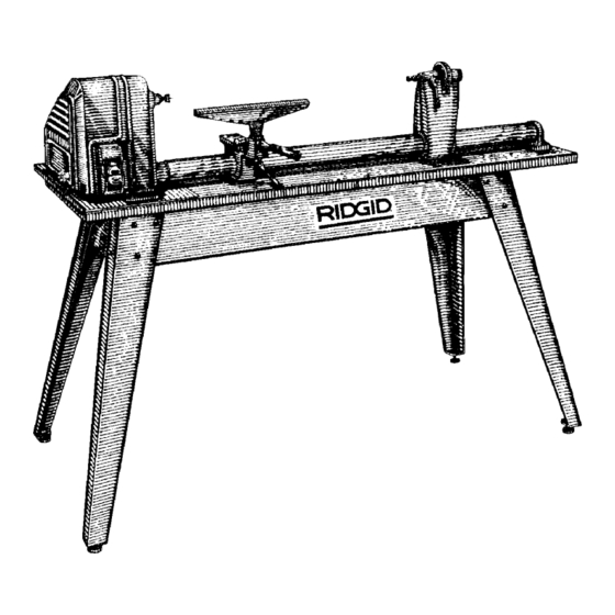
- Page 1 W L 1 2 0 0 O W N E R ’ S M A N U A L 1 2 I N C H W O O D T U R N I N G L A T H E F o r Y o u r S a f e t y : R e a d a l l i n s t r u c t i o n s c a r e f u l l y S a v e t h i s m a n u a l f o r f u t u r e r e f e r e n c e...
-
Page 2: Table Of Contents
When Installing Or Moving the Lathe ......3 Indexing ..............21 Before Each Use ............3 How To Use Your RIDGID Wood Lathe .....22 To Reduce the Risk of Injury From Jams, Slips Or Woodworking Chisels and How to Use Them ..22 Thrown Pieces (Kickbacks Or Throwbacks) .... -
Page 3: Safety Instructions For Wood Turning Lathe
Safety Instructions For Wood Turning Lathe Safety is a combination of common sense, staying alert and knowing how your lathe works. Read this manual to under- stand this tool. Safety Signal Words means if the safety information is not followed WARNING: someone could be seriously injured or killed. -
Page 4: To Reduce The Risk Of Injury From Jams, Slips Or Thrown Pieces (Kickbacks Or Throwbacks)
Safety Instructions For Wood Turning Lathe (continued) Use Recommended Accessories. • Follow the instructions that accompany the accessories. • To avoid injury from unsafe accessories, use only rec- WARNING: Use only accessories recommended for ommended accessories. this lathe. (Using other accessories may be danger- •... -
Page 5: Whenever Lathe Is Running
• Never attempt to remount a faceplate turning to the positive the lathe is set at the lowest speed before faceplate for any reason. Never attempt to remount a turning ON. between-centers turning if the original centers in the • Never mount a workpiece that contains any splits, turning have been altered or removed. -
Page 6: Wire Sizes
If the motor is turning counterclockwise, remove the plug from the power outlet and contact 1-800-4-RIDGID. Unpacking and Checking Contents Tools Needed Medium Screwdriver... -
Page 7: List Of Loose Parts
List of Loose Parts Item Description Qty. Item Description Qty. Belt Guard Assembly......... 1 Screw, Pan Hd. M8 x 1.25-45......1 Headstock ............1 Screw, Pan Hd. M5 x 0.8-12.......4 Motor Pulley ............1 Screw Socket Set M10 x 1.5-12 ......1 V-Belt.............. -
Page 8: Assembly
Assembly Assembling Steel Legset 1. Find the following legset pieces: 4 Legs Side Stiffener 2 Side Stiffeners 2 End Stiffeners End Stiffener 2. From the loose parts package find the following items: 24 Carriage Bolts M8 x 1.25-16 24 Lockwashers M8 External Type 24 Hex Nuts,M8 x 1.25 24 Washer M8 x 16 x 1.6 8 Hex Nuts, 3/8-16... -
Page 9: Holes Used For Mounting Boards And Wood Lathe To Leg Set
Holes Used for Mounting Boards and Wood Lathe to Leg Set A - Board/Side Support F - Bracket Plate/Plate Support/Board/Side Support B - Board/Side Support G - Belt Gaurd/Plate Support C - Plate Support/Board/End Support H - Motor/Plate Support D - Board/End Support J - Cord Clamps/Plate Support E - Headstock/Plate Support/Board K - Rear Foot/Board... -
Page 10: Mounting Right Side Table Top
Assembly (continued) Mounting Right Side Table Top 1. Find the following: Particle Board Table Top 2. From the loose parts package find the following: M6 x 1.0-45 Carriage Bolts M6 x 1.0 Hex Head Nuts 6.5 x 19 x 1.6 Flat Washers 6mm Lockwashers 3. -
Page 11: Mounting Headstock
Mounting Headstock 1. Find the following: Belt Guard Assembly Headstock Assembly Plate Bracket 2. From the loose parts package find the following: M6 x 1.0-65 Carriage Bolts Bracket Belt Guard M6 x 1.0-45 Carriage Bolt Plate Assembly Headstock M6 x 1.0-12 Hex Head Screw Assembly M6 x 1.0 Hex Nuts 6.5 x 19 x 1.6 Flat Washers... -
Page 12: Mounting The Motor
Assembly (continued) Mounting the Motor 1. Find the following: Motor Motor Pulley Motor Pulley Cord Clamp Cord Clamps Motor V-Belt 2. From the loose parts package find the following: M4 x 0.7-6 Pan Head Screws Pan Screw Carriage Bolt M6 x 1.0-16 Carriage Bolts M4 x 0.7-6 M6 x 1.0-16 V-Belt... -
Page 13: Headstock,Tailstock, And Tool Rest Assembly
Headstock,Tailstock, and Tool Rest Assem- 1. Find the following: Tube Lever Assembly Large Tool Rest Tube Tailstock Lever Assembly Socket Set Screw M10 x 1.5-12 Brass Shoe Lock Tool Rest Holder/Clamp Support Assembly Tailstock Brass Shoe Locks 5mm Hex “L” Wrench Large Tool Rest Socket Set Screw M10 x 1.5-12... -
Page 14: Mounting Rear Foot
Assembly (continued) 6. Slide tailstock assembly onto the tube and install tail- Tailstock Ram stock ram spindle lock lever. Be sure that the stud nut Spindle Lever engages the keyed way of the spindle. Assembly Keyed Way Headstock End Tailstock Assembly 7. -
Page 15: Spur And Cup Center Installation
Spur and Cup Center Installation 1. From the loose parts package find the following: 3/4-16 Hex Nut Spur Center Cup Center Hex Nut 3/4-16 2. Screw nut onto head stock spindle until finger tight. 3. To insert point into centers, place center between jaws of a vise. -
Page 16: Check Spindle Rotation
Assembly (continued) Check Spindle Rotation Rotation The lathe spindle must rotate counterclockwise when Terminal viewed from the spindle end. Cover NOTE: Make sure the spur center is removed from the spindle. 1. Plug the lathe power cord into a properly grounded outlet (See page 5) 2. -
Page 17: Getting To Know Your Wood Lathe
Getting To Know Your Wood Lathe Index Pin Tailstock Handwheel Cup Center Spindle Lock Hole Spur Tool Rest Tailstock Ram Center Lock Belt Guard Tool Rest Base Foot Spindle Speed Tailstock Chart Tool Rest Base Lock Belt Guard Tailstock Knob Lock Headstock Tool Rest... -
Page 18: On-Off Switch
Getting To Know Your Wood Lathe (continued) On-off Switch WARNING: Don't connect power cord to electrical outlet in your shop until you are sure that motor rotation is correct (see page 6). The On-Off Switch has a locking feature. This Feature Is Intended To Prevent Unauthorized And Possible Haz- ardous Use By Children And Others. -
Page 19: Basic Lathe Operations
Basic Lathe Operations WARNING: For your own safety, turn switch "OFF" Motor and remove plug from power source outlet before Pulley making any adjustments. Rotate Counterclockwise Changing Speeds The belt is shown positioned on the second steps from the outside end of the pulleys. This causes the lathe to run 2250 R.P.M. -
Page 20: Spindle Turning
Basic Lathe Operations (continued) Spindle Turning WARNING: For your own safety, turn switch "OFF" and remove switch key before mounting workpiece in lathe. If you have never done any amount of wood turning, we suggest that you practice using the various wood turning tools. -
Page 21: Indexing
Look at the speed chart. Notice that a 2" square turning up to 18" long should run at 875 R.P.M. for "roughing". Move the V- belt on the pulleys to the slowest speed as outlined under "Changing Speeds" section. WARNING: For your own safety rotate the wood by hand to make sure that the corners do not strike the tool rest or anything else before turning the lathe "ON". -
Page 22: How To Use Your Ridgid Wood Lathe
How To Use Your RIDGID Wood Lathe Woodworking Chisels and How to Use Them Gouge Skew Parting Tool Spear Point Flat Nose Round Nose The Six Commonly Used Chisel Types Selection Of Chisels Better chisels have handles approximately 10-in. long, to provide plenty of grip and leverage. - Page 23 Rest too Steady Force No support high - Thrust bevel Against Kickback Chatter point Hands Rest Bevel digging too low. against chisel Kickback work too high on work. Chisel Chisel Rest too low; too high. cutting chisel too horizontal. properly Small Handle Large...
-
Page 24: Using The Gouge
How to Use Your RIDGID Wood Lathe (continued) How to Position Tool Rest for Circumference Scraping Edge In scraping operations, the tool rest position is not as crit- Digging ical as it is for cutting operations. The chisel generally is held horizontally, though it can be held at an angle to reach into tight places. -
Page 25: Using The Parting Tool
Using The Parting Tool Cutting Scraping The parting tool has just one primary purpose: to cut straight into the workpiece as deep as desired, or all the way through to make a cut-off. It is therefore a very narrow tool - 1/8-in. wide - and is shaped to cut its own clearance so that the edge will not be burned. -
Page 26: Using Wood Rasps And Files
How to Use Your RIDGID Wood Lathe (continued) Using Wood Rasps And Files A wood rasp will remove stock quickly when held against the revolving workpiece. Care should be taken to support the rasp firmly against the tool rest, however, as it can tear the hands painfully if caught by a rough edge of the work- piece and kicked back. -
Page 27: Making Standard Cuts
Making Standard Cuts The Roughing-off Cut Reducing a square or odd-shaped workpiece down to a cylinder of approximate size for finish turning is called “Roughing-off”. Faceplate turning and large diameter spindles should first be partly reduced by sawing but small spindles are easily turned down entirely with the large (3/4-in.) gouge. - Page 28 How to Use Your RIDGID Wood Lathe (continued) Smoothing A Cylinder The final 1/8-in. can be removed in two ways. Either use the 1 -in. skew, working from center toward both ends and taking lighter and lighter cuts until finished.
- Page 29 Cutting Beads This requires considerable practice, First, make pencil lines to locate the tops (highest points) of two or more ad- joining beads. Then make a vee groove at the exact cen- ter between two lines - and down to the desired depth of the separation between the beads.
-
Page 30: How To Handle Spindle Turnings
How to Use Your RIDGID Wood Lathe (continued) Making Long Convex Cuts First turn work down to approximate size, using sizing cuts (as required) to determine various diameters. Finish cut can then be made with either skew or gouge. If the skew is used, the principles of the operation are the same as those employed in cutting a bead - except that curve is longer and may be irregular. -
Page 31: Duplicate Turnings
Duplicate Turnings Identical turnings require great accuracy when plotting the work and doing the various cuts. Many methods have been devised to aid in perfecting the work. Use of Patterns Professional workers generally use a pattern, or layout board. This is a thin piece of wood or cardboard on which is drawn a full- size half section of the turning. -
Page 32: Long Spindles
How to Use Your RIDGID Wood Lathe (continued) Long Spindles A long turning can be worked in short sections, with joints arranged to be at shoulders where they will not be noticed. Long thin work that is likely to whip while turning should be supported at one or two places by a backstick. -
Page 33: Miscellaneous Operations
Miscellaneous Operations Guide Blocks For Scraping Operations A guide block can be clamped to a chisel to limit the depth of cut and aid in the production of perfect cylinders, tapers and facings on faceplate turnings. Scraping methods must be used when the guide block is employed. Drilling Cross Drilling For cross drilling flat sided work, use a (metal-lathe) drill... -
Page 34: How To Make Fancy Faceplate Turnings
How To Use Your RIDGID Wood Lathe (continued) Deep Recesses The first step is to remove as much wood as possible by boring into the center with the largest wood bit available. This can be accomplished as illustrated. Be careful to measure in advance the depth to which drill can be al- lowed to go. - Page 35 Turning Cylinders Stock for cylinders should be mounted on the screw cen- ter or a small faceplate. The tailstock can be brought up to support the work while the circumference is being turned and finished. Afterwards, the tailstock is backed off and the outer end of the cylinder is recessed, using methods already described for making deep recesses.
- Page 36 How to Use Your RIDGID Wood Lathe (continued) Turning Balls Wooden balls of large size are first roughly turned be- tween centers, using standard procedures. Smaller balls can be mounted as faceplates on the small faceplate or screw center. Lines drawn to indicate the center and ends of the ball shape are helpful in plotting the curve.
- Page 37 Turned Boxes Turned boxes involve deep recessing together with a spe- cial system of working the lid and body of the box together as one unit. The inside of the lid is turned first. Next, the inside of the body is turned. A careful check must be made when turning the lip of the body portion so that the lid will be a tight press fit.
-
Page 38: How To Turn Plastics
How to Use Your RIDGID Wood Lathe (continued) How to Turn Plastics Types Of Plastics There are two general groups of plastics. The first in- cludes all phenol plastics molded under heat and pres- sure. Bakelite and Formica are examples. In the second... -
Page 39: Sanding, Buffing And Polishing
Sanding, Buffing And Polishing Using The Lathe To Sand Turnings Turnings should be sanded with the lathe running in sec- ond lowest speed. A large sheet of sandpaper is useful for smoothing cylinders. All other sanding operations are done with a narrow strip of abrasive paper. The best fin- ishing grit is 3/0 for softwoods, 4/0 for hardwoods. - Page 40 How to Use Your RIDGID Wood Lathe (continued) Use Of Sanding Drums Standard sanding drums are usually rubber cylinders which can be expanded to hold an abrasive sleeve in place. Similar cylinders turned on the lathe, and covered with abrasive paper glued or tacked in place, do satisfac- tory work.
-
Page 41: Wiring Diagram
WARNING: For Your Own Safety, Turn Switch 3. If disassembly of the motor is necessary, it should be "OFF" And Remove Plug From Power Source Outlet returned to your nearest RIDGID retail store in order Before Maintaining Or Lubricating Your Lathe. to prevent voiding the guarantee. -
Page 42: Troubleshooting
Troubleshooting General WARNING: For Your Own Safety, Turn Switch "OFF" And Remove Plug From Power Source Outlet Before Trouble Shooting. Trouble Probable Cause Remedy Motor will not run 1. Defective On-Off switch. 1. Replace defective parts before using lathe again. Defective switch cord. -
Page 43: Motor
Motor NOTE: Motors used on wood - working tools are particularly susceptible to the accumulation of sawdust and wood chips and should be blown out or “vacuumed” frequently to prevent interference with normal motor ventilation and proper op- eration of the centrifugally-operated starting switch. Trouble Probable Cause Remedy... -
Page 44: Motor Connections
Motor Connections WARNING: For Your Own Safety, Turn Switch Green Screw Terminal "OFF" And Remove Plug From Power Source Outlet Internal Before Proceeding. Lockwasher 1. Open motor connector box cover located on right end of motor (viewed from rear of motor) using a flat blade Black Wire to screwdriver. -
Page 45: Repair Parts
Repair Parts RIDGID 12" Wood Lathe Model No. WL12000 Figure 1 NOTE: Any attempt to repair this motor may create a hazard unless repair is done by qualified service technician. Repair service is available at an Authorized Service Center. Always order by Part Number -- Not by Key Number Part No. - Page 47 826593 Stud Nut 813317-8 Wrench Hex L M5 169123-11 Relief Strain 826570 Rest 6" Tool 826569 Bracket Plate 826601 Knob Guard * Standard Hardware Item - May Be Purchased Locally † This item is a RIDGID accessory available at Home-Depot...
- Page 48 Repair Parts RIDGID 12" Wood-Turning Lathe Model No. WL12000 Figure 3...
- Page 49 Repair Parts RIDGID 12" Wood-Turning Lathe Model No. WL12000 Figure 3 Always order by Part Number -- Not by Key Number Part No. Description 820377-1 Bolt Rd. Hd. Sq. Neck M6 x 1.0-45 826579 Plate Support 826619 Board Wood Lathe...
-
Page 50: Notes
Notes... - Page 51 Notes...
- Page 52 What is covered RIDGID® tools are warranted to be free of defects in workman- ship and material. How long coverage lasts This warranty lasts for the lifetime of the RIDGID® tool. Warranty coverage ends when the product becomes unusable for reasons other than defects in workmanship or material.