Table of Contents
Advertisement
USA
Security Division
Garrett Metal Detectors
1881 West State Street
Garland, Texas 75042-6797 USA
Phone:
(800) 234-6151
Fax:
(972) 494-1881
Email:
security@garrett.com
Website:
www.garrett.com
USER MANUAL
MODEL 11684xx
OUTSIDE USA
International Division
Garrett Metal Detectors
1881 West State Street
Garland, Texas 75042-6797 USA
Phone:
(972) 494-6151
Fax:
(972) 494-1881
Email:
international@garrett.com
Website:
www.garrett.com
PD 6500i
Advertisement
Table of Contents

Related Manuals for Garrett PD 6500i


Summary of Contents for Garrett PD 6500i
-
Page 1: User Manual
USER MANUAL PD 6500i MODEL 11684xx OUTSIDE USA Security Division International Division Garrett Metal Detectors Garrett Metal Detectors 1881 West State Street 1881 West State Street Garland, Texas 75042-6797 USA Garland, Texas 75042-6797 USA Phone: (800) 234-6151 Phone: (972) 494-6151... - Page 3 Maximum Altitude: 3000 meters Place the PD 6500i in an area where it is protected from direct rain, mist and / or condensation and position it on a level, stable floor free from vibration. CAUTION! PD 6500i may be firmly anchored to the floor or optional stabilizer base attached to reduce the risk of injury to persons or property damage due to accidental knock down.
-
Page 4: Table Of Contents
GARRETT PD 6500i USER MANUAL TABLE OF CONTENTS GENERAL DESCRIPTION OF PD 6500i TECHNICAL SPECIFICATIONS REGULATORY INFORMATION DESCRIPTION OF CONTROLS, DISPLAYS AND ALARMS INSTALLATION SITE SELECTION & REQUIREMENTS UNIT ASSEMBLY PLACEMENT PROCEDURE MULTIPLE WALK-THROUGH SITE INSTALLATION SETUP MENUS MENU TABLE... -
Page 5: General Description Of Pd 6500I
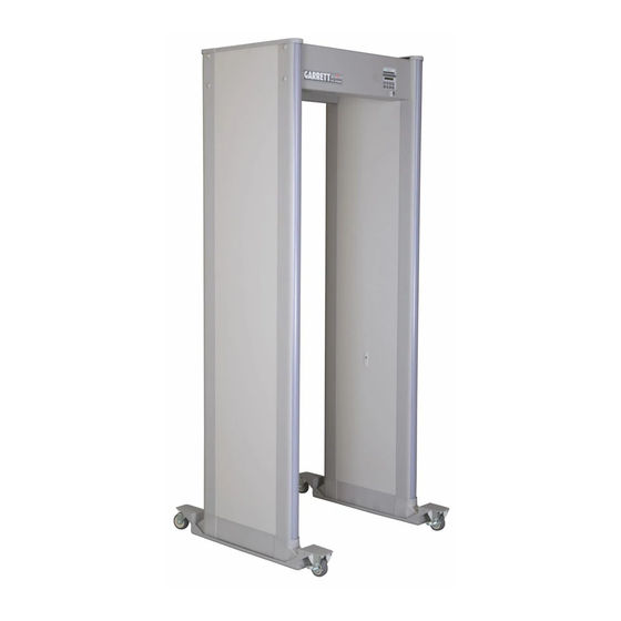
GARRETT PD 6500i USER MANUAL GENERAL DESCRIPTION OF PD 6500i Basic Description The Garrett PD 6500i (Model #11684xx) is a digitally controlled pulse induction metal detector. Memory All program selections and settings are maintained in electrically erasable non-volatile memory. The unit will maintain all settings even when disconnected from power. -
Page 6: Technical Specifications
(e.g., "hand wanding", "pat down", non-admittance, etc.) be a part of the overall security plan. The PD 6500i is made of scratch and mar resistant laminate with resilient end caps, a control panel and heavy-duty aluminum crosspiece. Smooth rounded corner design ensures no puncturing, cutting or tearing of the skin or clothing or otherwise causing bodily injury. - Page 7 • OSHA Regulation 1910.147 De-energizing Equipment. 1.2.2 MAGNETIC FIELD SAFETY The Garrett PD 6500i has been tested and found to comply with: • AICGH-0302 (1996), Sub-Radio Frequency (30 kHz and below) Magnetic Fields. • Institute of Electrical and Electronic Engineers (IEEE) C95.1-1999, "IEEE Standard for Safety Levels with Respect to Human Exposure to Radio Frequency Electromagnetic Fields, 3 kHz to 300 GHz.”...
-
Page 8: Description Of Controls, Displays And Alarms
1.3.1.2 READY LIGHT The green READY light appears when power is on and the PD 6500i is ready to detect metal. The ready light must be illuminated before a patron is permitted to enter the walk-through. - Page 9 Activate the manual self-test at any time by pressing OPERATE. 1.3.1.6.2 The OFF touchpad is used to turn the PD 6500i off, ensuring that all of the information and settings are stored in memory until the detector is ready to resume full operation.
- Page 10 GARRETT PD 6500i USER MANUAL 1.3.1.6.5 (+) and (–) The plus (+) and minus (–) touchpads are used to change numerical settings, activate certain on/off functions and adjust the volume of the audio alarm. 1.3.1.6.6 PROGRAM DISPLAY The PROGRAM DISPLAY touchpad enables the user to view the program and base sensitivity settings on the LCD.
-
Page 11: Installation
In all cases, the PD 6500i must be installed on a level, stable floor. The following site require- ments are provided as guidelines to a successful installation. - Page 12 This can be easily accomplished using power cords if existing power does not, or cannot, meet this requirement. Garrett metal detectors are very versatile and can be connected to power from either their top or bottom of either side. This makes connecting power very convenient and gives the user more options when designing their sites.
- Page 13 GARRETT PD 6500i USER MANUAL 2.1.3 SPACING AND CONFIGURATION A site must also allow for efficient spacing and configuration of metal detectors. If a site is too small the operation of the checkpoint becomes "choked" and "bottlenecks" form. This severely hampers the flow of "traffic"...
- Page 14 GARRETT PD 6500i USER MANUAL ONE LINE CONFIGURATION (40’x20’ TENT) ©2003 GARRETT METAL DETECTORS PN 1532010 REV A...
- Page 15 GARRETT PD 6500i USER MANUAL TWO LINE CONFIGURATION (40’x40’ TENT) ©2003 GARRETT METAL DETECTORS PN 1532010 REV A...
-
Page 16: Unit Assembly
GARRETT PD 6500i USER MANUAL 2.1.4 INTERFERENCE Many variables can potentially cause interference with any metal detector operation. However, there are some major variables to address. Electrical sources of interference, generators, transformers, electrical panels, etc., should be kept as far away as possible. Large metallic objects moving or stationary, revolving doors, elevators, garbage cans, barricades, etc.,... - Page 17 GARRETT PD 6500i USER MANUAL 3. Place any one of six packing inserts on floor as shown in Figure 2–2. Lay detection unit (with touchpad panel facing down) on packing insert. Connect detection unit to panels A and B using four screws and finishing washers.
- Page 18 7. If optional stabilizer mounts are to be used, attach stabilizer plates to side panels. Do not remove adhesive protectors at this time. 8. Use two or more people to lift PD 6500i to a vertical position and move to desired location. (See Figure 2–5) FIGURE 2-5 9.
-
Page 19: Placement Procedure
Anchor the unit to the floor, using the 1/4" mounting holes located at the base of each panel. Position the PD 6500i in the desired location. Using the panels as guides, mark and drill holes, then secure the walk-through using the appropriate mounting devices. -
Page 20: Multiple Walk-Through Site Installation Setup
Procedure: 1. Set all PD 6500i’s synchronization MASTER. 2. Set end unit (i.e., first or last in a series of PD 6500i 's) to CHANNEL 1. 3. Set next unit to CHANNEL 2. 4. Set next unit to CHANNEL 1. - Page 21 (See Figure 2-7) 6. Replace covers and reconnect power. 7. Set the end unit (i.e., first or last in a series of PD 6500i's) synchronization to MASTER CHANNEL 1 and make sure it is always connected to either AC power or battery power.
-
Page 22: Menus
USER MANUAL MENUS There are three access levels of security clearance (Operator, Supervisor and Administrator) for the PD 6500i. Operator: This access level has the ability to view and alter authorized Monitor Functions (see Table 3.1) of the walk-through. These Monitor Functions may be viewed by the Operator without a user login. -
Page 23: Menu Table
GARRETT PD 6500i USER MANUAL 3.1. MENU TABLE The following table lists access levels and menu functions. TABLE 3.1 Function Operator* Supervisor Administrator Default Access Code Not Required 1234 5678 Power Off / On Off / On Off / On... -
Page 24: Power On / Off
Each user may scroll through the menu items assigned to their particular level. Some menu items are available as "view only". The PD 6500i will not allow this user to change any of the "view only" items. To scroll the menu items, use the ACCESS touchpad;... - Page 25 GARRETT PD 6500i USER MANUAL 3.5.1 PROGRAM PROG: <current program set>, will appear on LCD. If user is authorized to change the program, the user may scroll the menu of programs using the + / - touchpads to find the new program. Stop scrolling when program desired appears on LCD.
- Page 26 GARRETT PD 6500i USER MANUAL 3.5.5 ALARM COUNT A built-in and user resettable alarm counter records the number of alarms that have occurred. This is a "view only" menu item. The alarm count is automatically reset to zero when the patron counter is reset.
- Page 27 GARRETT PD 6500i USER MANUAL PACE LIGHTS <ON / OFF>, appears on LCD. If user is authorized to change the pacing lights, the user may use the + (pacing lights on) / - (pacing lights off) touchpads to set pacing lights.
- Page 28 A number greater than 50 will elicit the message, RX BAL #, and the pinpoint lights within the problem zone will illuminate. Should this occur, ensure that there is no large metal object adjacent to the PD 6500i. Then, ensure that the balance number has fallen below 50 and the corresponding pinpoint lights are off.
- Page 29 Press ACCESS for the next adjustment or OPERATE to resume normal operation. CAUTION! When using any other Garrett walk-through metal detectors with PD 6500i’s, use channels A and B to coincide with other Garrett walk-through channels A and B. 3.5.18...
- Page 30 GARRETT PD 6500i USER MANUAL walk-through (alarms should occur with each pass), particularly in locations and orientations where you suspect detection is most difficult. Alarms will occur if sensitivity setting is correct. After choosing the base sensitivity, press ACCESS to make another adjustment or OPERATE to resume normal operation.
- Page 31 GARRETT PD 6500i USER MANUAL FIGURE 3-1 ©2003 GARRETT METAL DETECTORS PN 1532010 REV A...
- Page 32 GARRETT PD 6500i USER MANUAL ZONE 5-6 (ZONE 5=150+0%) The sensitivity of the last two zones can be adjusted from -63% to +192% of the base sensitivity. For example an adjustment of zero percent means that the sensitivity of a given zone is equal to the base sensitivity.
-
Page 33: Code Reset
Press ACCESS for the next adjustment or OPERATE to resume normal operation. CODE RESET Should the administrator access code be forgotten or misplaced, the PD 6500i has a mechanical method for resetting the administrator access code to factory preset code. -
Page 34: Programs
GARRETT PD 6500i USER MANUAL PROGRAMS The PD 6500i offers several programs designed to help meet specific security needs. TABLE 4.2 PROGRAM DESCRIPTION / USE(S) Airports Designed primarily for detection of guns and other such weapons. Exceeds Schools FAA detection requirements (i.e. FAA 3-gun test). Provides excellent... -
Page 35: Maintenance / Troubleshooting
GARRETT PD 6500i USER MANUAL Good Conductors (Aluminum, Fine Jewelry) Most Common Stainless Steel Detectability Poor Conductors (Foils, Costume Jewelry) Ferrous (Iron, Tools) Loss Prevention Program FIGURE 4-1 MAINTENANCE / TROUBLESHOOTING WARRANTY INFORMATION Garrett Electronics, Inc. ("Garrett") warrants that each piece of security equipment manufactured by Garrett is protected by the following limited parts and labor warranty for a period of 24 (twenty-four) months (the "Warranty"). -
Page 36: Repair
GARRETT PD 6500i USER MANUAL REPAIR The PD 6500i ’s modular design facilitates assembly and maintenance. If problems are site-related, see Section 2.1 or contact the factory for assistance. Often adjusting or relocating the equipment, or removing nearby objects resolves problems. - Page 37 GARRETT PD 6500i USER MANUAL FIGURE 5-2 FIGURE 5-3 FIGURE 5-4 ©2003 GARRETT METAL DETECTORS PN 1532010 REV A...
-
Page 38: Replacement Parts List
GARRETT PD 6500i USER MANUAL REPLACEMENT PARTS LIST TABLE 5-3 ITEM DESCRIPTION PART # Access Code Card 1562300 User’s Manual 1532010 VHS Video Tape 1678400 Detection Unit 2233450 Panel A Fin 2233200 Panel B Fin 2233300 TX/Controller Board Pcb Assembly... -
Page 39: Error Code Table-Diagnostics
When a critical failure occurs, the audio alarm sounds, the overhead display begins flashing and the message, SYSTEM FAILURE, appears on the LCD. A non-critical failure does not prevent the PD 6500i from operating; however, it should be corrected as soon as possible. - Page 40 Ensure no large metal object FAIL 2. Circuit Board Connects nearby. If necessary, move (# = zone with balance failure) object or relocate PD 6500i. RXB Zn # BAL 1. Cable and connectors to panel B Ensure no large metal object FAIL 2.
-
Page 41: Accessories
GARRETT PD 6500i USER MANUAL ACCESSORIES BATTERY PACK MODULE (OPTIONAL) The battery pack module is a field-installable assembly that provides approximately eight hours of uninterrupted operation. A monitoring circuit ensures that the two 12V batteries charge within 12 hours and then switch to trickle charge to ensure maximum charge without battery damage. - Page 42 GARRETT PD 6500i USER MANUAL FIGURE 6-2 Procedure: 1. Disconnect from AC power. 2. Open access door of detection unit. 3. Remove the three screws that hold controller cover. Remove the terminal connector. 4. Connect the relay or device to controller circuit board, as shown.
-
Page 43: Additional Information
GARRETT PD 6500i USER MANUAL ADDITIONAL INFORMATION SECURING THE POWER CORD Section 2 of this manual describes the connection of the power cord to either side of the base of the unit. This connection is made with an IEC rated connection that allows easy removal of the unit for maintenance, emergency, etc. - Page 44 Copyright ©2003 Garrett Metal Detectors. All Rights Reserved 1532010 REV. A ©2003 GARRETT METAL DETECTORS PN 1532010 REV A...