Table of Contents
Advertisement
Advertisement
Chapters
Table of Contents

Related Manuals for Asus H61M-PRO


Summary of Contents for Asus H61M-PRO
- Page 1 H61M-PRO...
- Page 2 Product warranty or service will not be extended if: (1) the product is repaired, modified or altered, unless such repair, modification of alteration is authorized in writing by ASUS; or (2) the serial number of the product is defaced or missing.
-
Page 3: Table Of Contents
Contents Safety information ...................... iv About this guide ......................iv Package contents ....................... vi H61M-PRO specifications summary ................. vi Product introduction Before you proceed ..................1-1 Motherboard overview ................. 1-1 Central Processing Unit (CPU) ..............1-3 System memory .................... 1-6 Expansion slots .................... -
Page 4: Safety Information
Safety information Electrical safety • To prevent electrical shock hazard, disconnect the power cable from the electrical outlet before relocating the system. • When adding or removing devices to or from the system, ensure that the power cables for the devices are unplugged before the signal cables are connected. If possible, disconnect all power cables from the existing system before you add a device. -
Page 5: Conventions Used In This Guide
Refer to the following sources for additional information and for product and software updates. ASUS websites The ASUS website provides updated information on ASUS hardware and software products. Refer to the ASUS contact information. Optional documentation Your product package may include optional documentation, such as warranty flyers, that may have been added by your dealer. -
Page 6: Package Contents
DDR3 1600 MHz and higher memory frequency is supported by Intel ® • 3rd generation processors. Refer to www.asus.com for the latest Memory QVL (Qualified Vendors • List). When you install a total memory of 4GB capacity or more, Windows ®... - Page 7 ® - 8 x USB 2.0/1.1 ports (4 ports at the mid-board, 4 ports at the back panel) ASMedia ASM1042 USB3.0 controller - support ASUS 3.0 Boost UASP ® Mode - 2 x USB 3.0 ports at mid-board Rear panel ports...
- Page 8 BIOS features 64 Mb Flash ROM, UEFI BIOS, PnP, DMI v2.0, WfM 2.0, ACPI v2.0a, SM BIOS v2.7, SLP 3.0, Multi-language BIOS, ASUS EZ Flash 2, ASUS CrashFree BIOS 3, F12 PrintScreen function, F3 Shortcut function, and ASUS DRAM SPD (Serial Presence Detect) memory information...
-
Page 9: Product Introduction
1.2.2 Screw holes Place six screws into the holes indicated by circles to secure the motherboard to the chassis. Do not overtighten the screws! Doing so can damage the motherboard. ASUS H61M-PRO... -
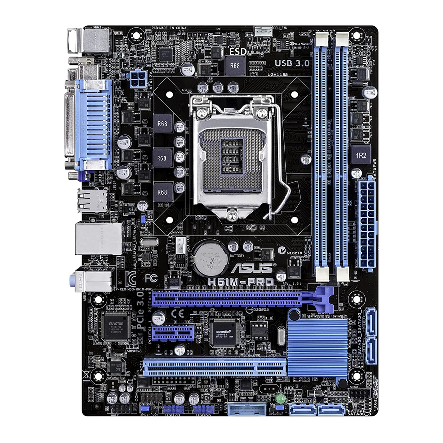
Page 10: Motherboard Layout
Place this side towards the rear of the chassis H61M-PRO 1.2.3 Motherboard layout 17.8cm(7.0in) KBMS CPU_FAN 8876 ATX12V USB34 CHA_FAN LAN_USB12 BATTERY 8111G AUDIO H61M-PRO PCIEX16 Super 64Mb PCIEX1_1 BIOS 1083 Intel ® PCI1 887-VD2 1042 SB_PWR AAFP USB3_E12 SATA3G_4... -
Page 11: Central Processing Unit (Cpu)
Contact your retailer immediately if the PnP cap is missing, or if you see any damage to the PnP cap/socket contacts/motherboard components. ASUS will shoulder the cost of repair only if the damage is shipment/ transit-related. -
Page 12: Cpu Installation
1.3.1 CPU installation The LGA1156 CPU is not compatible with the LGA1155 socket. DO NOT install an LGA1156 CPU on the LGA1155 socket. Chapter 1: Product introduction... -
Page 13: Cpu Heatsink And Fan Assembly Installation
1.3.2 CPU heatsink and fan assembly installation Apply the Thermal Interface Material to the CPU heatsink and CPU before you install the heatsink and fan if necessary. To install the CPU heatsink and fan assembly ASUS H61M-PRO... -
Page 14: System Memory
DDR2 DIMM socket. DDR3 modules are developed for better performance with less power consumption. The figure illustrates the location of the DDR3 DIMM sockets: Channel Sockets Channel A DIMM_A1 H61M-PRO Channel B DIMM_B1 H61M-PRO 240-pin DDR3 DIMM sockets Chapter 1: Product introduction... -
Page 15: Memory Configurations
2.4 Ai Tweaker menu for manual memory frequency adjustment. • For system stability, use a more efficient memory cooling system to support a full memory load (2 DIMMs) or overclocking condition. ASUS H61M-PRO... -
Page 16: Installing A Dimm
1.4.3 Installing a DIMM To remove a DIMM Chapter 1: Product introduction... -
Page 17: Expansion Slots
When using PCI cards on shared slots, ensure that the drivers support “Share IRQ” or that the cards do not need IRQ assignments. Otherwise, conflicts will arise between the two PCI groups, making the system unstable and the card inoperable. ASUS H61M-PRO... -
Page 18: Pci Slot
1.5.3 PCI slot The PCI slot supports cards such as a LAN card, SCSI card, USB card, and other cards that comply with PCI specifications. 1.5.4 PCI Express 2.0 x1 slot This motherboard supports PCI Express 2.0 x1 network cards, SCSI cards, and other cards that comply with the PCI Express specifications. -
Page 19: Jumpers
H61M-PRO Normal Clear RTC (Default) H61M-PRO Clear RTC RAM To erase the RTC RAM: Turn OFF the computer and unplug the power cord. Move the jumper cap from pins 1-2 (default) to pins 2-3. Keep the cap on pins 2-3 for about 5~8 seconds, then move the cap back to pins 1-2. -
Page 20: Ps2 And Usb Device Wake-Up (3-Pin Ps2_Usbpw1~4)
DRAM in slow refresh, power supply in reduced power mode). USBPW5-8 H61M-PRO +5VSB (Default) H61M-PRO USB Device Wake Up • The USB device wake-up feature requires a power supply that can provide 500mA on the +5VSB lead for each USB port; otherwise, the system would not power up. •... -
Page 21: Rear Panel Ports
Rear Speaker Out Rear Speaker Out Lime (Rear panel) Line Out Front Speaker Out Front Speaker Out Front Speaker Out Pink (Rear panel) Mic In Mic In Bass/Center Bass/Center Lime (Front panel) – – – Side Speaker Out ASUS H61M-PRO 1-13... -
Page 22: Internal Connectors
H61M-PRO HD-audio-compliant Legacy AC’97 pin definition compliant definition H61M-PRO Front panel audio connector • We recommend that you connect a high-definition front panel audio module to this connector to avail of the motherboard’s high-definition audio capability. • If you want to connect a high-definition front panel audio module to this connector, set the Front Panel Type item in the BIOS setup to [HD]. -
Page 23: Atx Power Connectors (24-Pin Eatxpwr, 4-Pin Atx12V)
• If you are uncertain about the minimum power supply requirement for your system, refer to the Recommended Power Supply Wattage Calculator at http://support.asus. com/PowerSupplyCalculator/PSCalculator.aspx?SLanguage=en-us for details. Digital audio connector (4-1 pin SPDIF_OUT) This connector is for an additional Sony/Philips Digital Interface (S/PDIF) port. -
Page 24: Usb 3.0 Connector (20-1 Pin Usb3_E12)
USB 3.0 including faster data transfer speeds of up to 5Gbps, faster charging time for USB-chargeable devices, optimized power efficiency, and backward compatibility with USB 2.0. USB3_E12 PIN 1 H61M-PRO H61M-PRO USB3.0 Front panel connector The USB 3.0 module is purchased separately. 1-16 Chapter 1: Product introduction... -
Page 25: Cpu And Chassis Fan Connectors (4-Pin Cpu_Fan, 4-Pin Cha_Fan)
The two fan connectors support fans of maximum 2A (24 W) fan power. • Only the 4-pin CPU fan and 4-pin chassis fan support the ASUS Fan Xpert feature. USB connectors (10-1 pin USB56, USB78) These connectors are for USB 2.0 ports. Connect the USB module cable to any of these connectors, then install the module to a slot opening at the back of the system chassis. -
Page 26: System Panel Connector (10-1 Pin F_Panel)
PIN 1 H61M-PRO +HDD_LED- RESET H61M-PRO System panel connector • System power LED (2-pin PWR_LED) This 2-pin connector is for the system power LED. Connect the chassis power LED cable to this connector. The system power LED lights up when you turn on the system power, and blinks when the system is in sleep mode. -
Page 27: Onboard Leds
This connector is for a serial (COM) port. Connect the serial port module cable to this connector, then install the module to a slot opening at the back of the system chassis. PIN 1 H61M-PRO H61M-PRO Serial port (COM) Connector The COM module is purchased separately. Onboard LEDs Standby Power LED The motherboard comes with a standby power LED that lights up to indicate that the system is ON, in sleep mode, or in soft-off mode. -
Page 28: Software Support
The contents of the Support DVD are subject to change at any time without notice. Visit the ASUS website at www.asus.com for updates. To run the Support DVD Place the Support DVD into the optical drive. -
Page 29: Bios Information
Managing and updating your BIOS Save a copy of the original motherboard BIOS file to a USB flash disk in case you need to restore the BIOS in the future. Copy the original motherboard BIOS using the ASUS Update utility. -
Page 30: Asus Ez Flash
2.1.3 ASUS CrashFree BIOS 3 utility The ASUS CrashFree BIOS 3 is an auto recovery tool that allows you to restore the BIOS file when it fails or gets corrupted during the updating process. You can restore a corrupted BIOS file using the motherboard support DVD or a USB flash drive that contains the updated BIOS file. -
Page 31: Recovering The Bios
2.1.4 ASUS BIOS Updater The ASUS BIOS Updater allows you to update BIOS in DOS environment. This utility also allows you to copy the current BIOS file that you can use as a backup when the BIOS fails or gets corrupted during the updating process. -
Page 32: Updating The Bios File
To update the BIOS file using BIOS Updater: At the FreeDOS prompt, type bupdater /pc /g and press <Enter>. The BIOS Updater screen appears as below. ASUSTek BIOS Updater for DOS V1.30 Current ROM Update ROM BOARD: H61M-PRO BOARD: Unknown VER: 0205 VER: Unknown... -
Page 33: Bios Setup Program
The BIOS setup screens shown in this section are for reference purposes only, and may not exactly match what you see on your screen. • Visit the ASUS website at www.asus.com to download the latest BIOS file for this motherboard. •... - Page 34 EZ Mode By default, the EZ Mode screen appears when you enter the BIOS setup program. The EZ Mode provides you an overview of the basic system information, and allows you to select the display language, system performance mode and boot device priority. To access the Advanced Mode, click Exit/Advanced Mode, then select Advanced Mode or press F7 hot key for the advanced BIOS settings.
-
Page 35: Advanced Mode
The Advanced Mode provides advanced options for experienced end-users to configure the BIOS settings. The figure below shows an example of the Advanced Mode. Refer to the following sections for the detailed configurations. To access the EZ Mode, click Exit, then select ASUS EZ Mode. Back button Menu items... -
Page 36: Menu Items
Menu items The highlighted item on the menu bar displays the specific items for that menu. For example, selecting Main shows the Main menu items. The other items (Ai Tweaker, Advanced, Monitor, Boot, Tool, and Exit) on the menu bar have their respective menu items. -
Page 37: Main Menu
RAM to clear the BIOS password. See section 1.7 Jumpers for information on how to erase the RTC RAM. • The Administrator or User Password items on top of the screen show the default Not Installed. After you set a password, these items show Installed. ASUS H61M-PRO... -
Page 38: Administrator Password
Administrator Password If you have set an administrator password, we recommend that you enter the administrator password for accessing the system. Otherwise, you might be able to see or change only selected fields in the BIOS setup program. To set an administrator password: Select the Administrator Password item and press <Enter>. -
Page 39: Ai Tweaker Menu
<-> keys to adjust the value. To restore the default setting, type [auto] using the keyboard and press <Enter>. Changing the values in this menu may cause the system to become unstable! If this happens, revert to the default settings. ASUS H61M-PRO 2-11... -
Page 40: Cpu Power Management
2.4.4 CPU Power Management The sub-items in this menu allow you to set the CPU ratio and features. CPU Ratio [Auto] Allows you to manually adjust the maximum non-turbo CPU ratio. Use <+> and <-> keys or the numeric keypad to adjust the value. The valid value ranges vary according to your CPU model. -
Page 41: Advanced Menu
The Intel Hyper-Threading Technology allows a hyper-threading processor to appear as two logical processors to the operating system, allowing the operating system to schedule two threads or processes simultaneously. [Enabled] Two threads per activated core are enabled. [Disabled] Only one thread per activated core is enabled. ASUS H61M-PRO 2-13... - Page 42 Active Processor Cores [All] Allows you to choose the number of CPU cores to activate in each processor package. Configuration options: [All] [1] [2] [3] Limit CPUID Maximum [Disabled] [Enabled] Allows legacy operating systems to boot even without support for CPUs with extended CPUID functions.
-
Page 43: Pch Configuration
Active Page Threshold size, the system will try to support the Intel(R) Rapid Start Technology. When the item is set to zero, the system automatically checks whether the partition size is enough at S3 entry. Key in the desired value using the numeric keypad. ASUS H61M-PRO 2-15... -
Page 44: Sata Configuration
Intel(R) Smart Connect Technology ISCT Configuration [Disabled] Allows you to enable or disable the ISCT configuration. Configuration options: [Enabled] [Disabled] 2.5.3 SATA Configuration While entering Setup, the BIOS automatically detects the presence of SATA devices. The SATA Port items show Not Present if no SATA device is installed to the corresponding SATA port. -
Page 45: Usb Configuration
Allows you to enable or disable an individual USB port. Refer to the section 1.2.3 Motherboard layout in this user manual for the locations of the USB ports. The USB port numbers may not be arranged in a consecutive order. ASUS H61M-PRO 2-17... -
Page 46: Onboard Devices Configuration
2.5.6 Onboard Devices Configuration HD Audio Controller [Enabled] [Enabled] Enables the High Definition Audio Controller. [Disabled] Disables the controller. The following two items appear only when you set the HD Audio Controller item to [Enabled]. Front Panel Type [HD] Allows you to set the front panel audio connector (AAFP) mode to legacy AC’97 or high- definition audio depending on the audio standard that the front panel audio module supports. -
Page 47: Parallel Port Configuration
Power On By PCIE/PCI [Disabled] [Disabled] Disables the PCIE/PCI devices to generate a wake event. [Enabled] Enables the PCIE/PCI devices to generate a wake event. Power On By Ring [Disabled] [Disabled] Disables Ring to generate a wake event. ASUS H61M-PRO 2-19... -
Page 48: Network Stack
[Enabled] Enables Ring to generate a wake event. Power On By RTC [Disabled] [Disabled] Disables RTC to generate a wake event. [Enabled] When set to [Enabled], the items RTC Alarm Date (Days) and Hour/ Minute/Second will become user-configurable with set values. RTC Alarm Date (Days) This item appears only when you set the previous item to [Enabled] and allows you to select RTC alarm time (days). -
Page 49: Monitor Menu
The onboard hardware monitor automatically detects and displays the CPU and chassis fan speeds in rotations per minute (RPM). If the fan is not connected to the motherboard, the field shows N/A. Select Ignore if you do not wish to display the detected speed. ASUS H61M-PRO 2-21... - Page 50 2.6.3 CPU Voltage, 3.3V Voltage, 5V Voltage, 12V Voltage The onboard hardware monitor automatically detects the voltage output through the onboard voltage regulators. Select Ignore if you do not want to detect this item. 2.6.4 CPU Q-Fan Control [Enabled] [Disabled] Disables the CPU Q-Fan control feature.
- Page 51 60% to 100%. When the chassis temperature is under 40ºC, the chassis fan will operate at the minimum duty cycle. 2.6.6 Anti Surge Support [Enabled] This item allows you to enable or disable the Anti Surge function. Configuration options: [Disabled] [Enabled] ASUS H61M-PRO 2-23...
-
Page 52: Boot Menu
Boot menu The Boot menu items allow you to change the system boot options. Scroll down to display the following items: 2-24 Chapter 2: Getting started... - Page 53 [Disabled] Disables the full screen logo display feature. Set this item to [Enabled] to use the ASUS MyLogo 2™ feature. POST Delay Time [3 sec] This item appears only when you set Full Screen Logo to [Enabled]. This item allows you to select the desired additional POST waiting time to easily enter the BIOS setup.
- Page 54 This feature will only work under normal boot. Post Report [5 sec] This item appears only when you set Full Screen Logo to [Disabled]. This item allows you to select a desired post report waiting time. The values range from 1 to 10 seconds. 2.7.3 Bootup NumLock State [On] [On]...
-
Page 55: Security Boot
Key-exchange Key (KEK) refers to Microsoft Secure Boot Key database (KEK). ® Clear Secure Boot keys This item appears only when you load the default Secure Boot keys. This item allows you to clear all default Secure Boot keys. ASUS H61M-PRO 2-27... - Page 56 Save Secure Boot Keys Allows you to save the PK (Platform Keys) to a USB storage device. PK Management The Platform Key (PK) locks and secures the firmware from any non-permissible changes. The system verifies the PK before your system enters the OS. Delete PK Allows you to delete the PK from your system.
-
Page 57: Boot Option Priorities
• To select the boot device during system startup, press <F8> when ASUS Logo appears. • To access Windows OS in Safe Mode, press <F8> after POST. -
Page 58: Tools Menu
<Enter> to display the submenu. 2.8.1 ASUS EZ Flash 2 Utility Allows you to run ASUS EZ Flash 2. Press [Enter] to launch the ASUS EZ Flash 2 screen. For more details, see section 2.1.2 ASUS EZ Flash 2. 2.8.2... -
Page 59: Exit Menu
This option allows you to exit the Setup program without saving your changes. When you select this option or if you press <Esc>, a confirmation window appears. Select Yes to discard changes and exit. ASUS EZ Mode This option allows you to enter the EZ Mode screen. Launch EFI Shell from filesystem device This option allows you to attempt to launch the EFI Shell application (shellx64.efi) from one of... - Page 60 2-32 Chapter 2: Getting started...
-
Page 61: Appendices
Cet appareil est conforme aux normes CNR exemptes de licence d’Industrie Canada. Le fonctionnement est soumis aux deux conditions suivantes : (1) cet appareil ne doit pas provoquer d’interférences et (2) cet appareil doit accepter toute interférence, y compris celles susceptibles de provoquer un fonctionnement non souhaité de l’appareil. ASUS H61M-PRO... -
Page 62: Canadian Department Of Communications Statement
ASUS Recycling/Takeback Services ASUS recycling and takeback programs come from our commitment to the highest standards for protecting our environment. We believe in providing solutions for you to be able to responsibly recycle our products, batteries, other components as well as the packaging materials. -
Page 63: Asus Contact Information
+1-812-282-3777 +1-510-608-4555 Web site usa.asus.com Technical Support Telephone +1-812-282-2787 Support fax +1-812-284-0883 Online support support.asus.com ASUS COMPUTER GmbH (Germany and Austria) Address Harkort Str. 21-23, D-40880 Ratingen, Germany +49-2102-959911 Web site www.asus.de Online contact www.asus.de/sales Technical Support Telephone +49-1805-010923* Support Fax... - Page 64 Appendices...