Table of Contents
Advertisement
Quick Links
Advertisement
Chapters
Table of Contents

Related Manuals for Asus H61M-G


Summary of Contents for Asus H61M-G
- Page 1 H61M-G E8188_H61M_G_manual.indb 1 2/12/14 2:56:51 PM...
- Page 2 Product warranty or service will not be extended if: (1) the product is repaired, modified or altered, unless such repair, modification of alteration is authorized in writing by ASUS; or (2) the serial number of the product is defaced or missing.
-
Page 3: Table Of Contents
Contents Safety information ...................... iv About this guide ......................iv Package contents ....................... vi H61M-G specifications summary ................vi Product introduction Before you proceed ..................1-1 Motherboard overview ................. 1-1 Central Processing Unit (CPU) ..............1-3 System memory .................... 1-7 Expansion slots .................... -
Page 4: Safety Information
Safety information Electrical safety • To prevent electrical shock hazard, disconnect the power cable from the electrical outlet before relocating the system. • When adding or removing devices to or from the system, ensure that the power cables for the devices are unplugged before the signal cables are connected. If possible, disconnect all power cables from the existing system before you add a device. -
Page 5: Conventions Used In This Guide
Refer to the following sources for additional information and for product and software updates. ASUS websites The ASUS website provides updated information on ASUS hardware and software products. Refer to the ASUS contact information. Optional documentation Your product package may include optional documentation, such as warranty flyers, that may have been added by your dealer. -
Page 6: Package Contents
2 x DIMMs, max. 16GB, DDR3 1600 / 1333 / 1066 MHz, non-ECC, un- buffered memory Dual-channel memory architecture Refer to www.asus.com for the latest Memory QVL (Qualified Vendors • List). When you install a total memory of 4GB capacity or more, Windows •... - Page 7 H61M-G specifications summary Audio Realtek ALC887 8-channel High Definition Audio CODEC ® Use a chassis with HD audio module in the front panel to support an • 8-channel audio output. Intel H61 Express Chipset: ® - 8 x USB 2.0/1.1 ports (4 ports at the mid-board, 4 ports at the back...
- Page 8 viii E8188_H61M_G_manual.indb 8 2/12/14 2:56:57 PM...
-
Page 9: Product Introduction
1.2.2 Screw holes Place six screws into the holes indicated by circles to secure the motherboard to the chassis. Do not overtighten the screws! Doing so can damage the motherboard. ASUS H61M-G E8188_H61M_G_manual.indb 1 2/12/14 2:56:59 PM... -
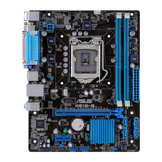
Page 10: Motherboard Layout
Place this side towards the rear of the chassis H61M-G 1.2.3 Motherboard layout 17.8cm(7.0in) KBMS CPU_FAN 8876 ATX12V USB34 CHA_FAN LAN_USB12 8111G AUDIO H61M-G PCIEX16 Super BATTERY SB_PWR Intel ® PCIEX1_1 887- VD2 AAFP USB56 USB78 BIOS SPEAKER F_PANEL Chapter 1: Product introduction E8188_H61M_G_manual.indb 2... -
Page 11: Central Processing Unit (Cpu)
The motherboard comes with a surface mount LGA1155 socket designed for the Intel 3rd / ® 2nd Generation Core™ i7, i5, i3, Pentium , and Celeron processors. ® ® H61M-G H61M-G CPU socket LGA1155 ASUS H61M-G E8188_H61M_G_manual.indb 3 2/12/14 2:57:01 PM... -
Page 12: Cpu Installation
Contact your retailer immediately if the PnP cap is missing, or if you see any damage to the PnP cap/socket contacts/motherboard components. ASUS will shoulder the cost of repair only if the damage is shipment/ transit-related. -
Page 13: Cpu Heatsink And Fan Assembly Installation
1.3.2 CPU heatsink and fan assembly installation Apply the Thermal Interface Material to the CPU heatsink and CPU before you install the heatsink and fan if necessary. ASUS H61M-G E8188_H61M_G_manual.indb 5 2/12/14 2:57:05 PM... - Page 14 To install the CPU heatsink and fan assembly To uninstall the CPU heatsink and fan assembly Chapter 1: Product introduction E8188_H61M_G_manual.indb 6 2/12/14 2:57:07 PM...
-
Page 15: System Memory
Sockets Channel A DIMM_A1 Channel B DIMM_B1 H61M-G H61M-G 240-pin DDR3 DIMM sockets 1.4.2 Memory configurations You may install 1GB, 2GB, 4GB, and 8GB unbuffered non-ECC DDR3 DIMMs into the DIMM sockets. • You may install varying memory sizes in Channel A and Channel B. The system maps the total size of the lower-sized channel for the dual-channel configuration. -
Page 16: Installing A Dimm
For system stability, use a more efficient memory cooling system to support a full memory load (2 DIMMs) or overclocking condition. • Visit the ASUS website at www.asus.com for the latest Memory QVL (Qualified Vendors List). 1.4.3 Installing a DIMM Chapter 1: Product introduction E8188_H61M_G_manual.indb 8... -
Page 17: Expansion Slots
Turn on the system and change the necessary BIOS settings, if any. See Chapter 2 for information on BIOS setup. Assign an IRQ to the card. Install the software drivers for the expansion card. ASUS H61M-G E8188_H61M_G_manual.indb 9 2/12/14 2:57:12 PM... -
Page 18: Irq Assignments For This Motherboard
When using PCI cards on shared slots, ensure that the drivers support “Share IRQ” or that the cards do not need IRQ assignments. Otherwise, conflicts will arise between the two PCI groups, making the system unstable and the card inoperable. 1.5.3 PCI Express 2.0 x1 slot This motherboard supports PCI Express 2.0 x1 network cards, SCSI cards, and other cards... -
Page 19: Jumpers
H61M-G Normal Clear RTC (Default) H61M-G Clear RTC RAM To erase the RTC RAM: Turn OFF the computer and unplug the power cord. Move the jumper cap from pins 1-2 (default) to pins 2-3. Keep the cap on pins 2-3 for about 5~10 seconds, then move the cap back to pins 1-2. -
Page 20: Usb Device Wake-Up (Usbpw5~8)
PS/2_USBPW1-4 H61M-G +5VSB (Default) H61M-G PS/2 and USB Device Wake-up • The USB device wake-up feature requires a power supply that can provide 500mA on the +5VSB lead for each USB port; otherwise, the system would not power up. •... -
Page 21: Connectors
Lime (Rear panel) Line Out Front Speaker Out Front Speaker Out Front Speaker Out Pink (Rear panel) Mic In Mic In Bass/Center Bass/Center Lime (Front panel) – – – Side Speaker Out ASUS H61M-G 1-13 E8188_H61M_G_manual.indb 13 2/12/14 2:57:22 PM... -
Page 22: Front Panel Audio Connector (10-1 Pin Aafp)
H61M-G HD-audio-compliant Legacy AC’97 pin definition compliant definition H61M-G Front panel audio connector • We recommend that you connect a high-definition front panel audio module to this connector to avail of the motherboard’s high-definition audio capability. • If you want to connect a high-definition front panel audio module to this connector, set the Front Panel Type item in the BIOS setup to [HD]. -
Page 23: Atx Power Connectors (24-Pin Eatxpwr, 4-Pin Atx12V)
• If you are uncertain about the minimum power supply requirement for your system, refer to the Recommended Power Supply Wattage Calculator at http://support.asus. com/PowerSupplyCalculator/PSCalculator.aspx?SLanguage=en-us for details. Speaker connector (4-pin SPEAKER) The 4-pin connector is for the chassis-mounted system warning speaker. - Page 24 480 Mbps connection speed. USB56 USB78 H61M-G PIN 1 PIN 1 H61M-G USB2.0 connectors Never connect a 1394 cable to the USB connectors. Doing so will damage the motherboard! The USB module cable is purchased separately. 1-16 Chapter 1: Product introduction E8188_H61M_G_manual.indb 16...
-
Page 25: Cpu And Chassis Fan Connectors (4-Pin Cpu_Fan, 4-Pin Cha_Fan)
• The two fan connectors support fans of maximum 2A (24 W) fan power. • Both the 4-pin CPU fan and 4-pin chassis fan are supported by the ASUS Fan Xpert feature. ASUS H61M-G 1-17 E8188_H61M_G_manual.indb 17... -
Page 26: Onboard Leds
PIN 1 H61M-G +HDD_LED RESET H61M-G System panel connector • System power LED (2-pin PWR_LED) This 2-pin connector is for the system power LED. Connect the chassis power LED cable to this connector. The system power LED lights up when you turn on the system power, and blinks when the system is in sleep mode. -
Page 27: Software Support
The contents of the Support DVD are subject to change at any time without notice. Visit the ASUS website at www.asus.com for updates. To run the Support DVD Place the Support DVD into the optical drive. - Page 28 1-20 Chapter 1: Product introduction E8188_H61M_G_manual.indb 20 2/12/14 2:57:33 PM...
-
Page 29: Bios Information
Managing and updating your BIOS Save a copy of the original motherboard BIOS file to a USB flash disk in case you need to restore the BIOS in the future. Copy the original motherboard BIOS using the ASUS Update utility. -
Page 30: Asus Ez Flash
2.1.2 ASUS EZ Flash 2 The ASUS EZ Flash 2 feature allows you to update the BIOS without using an OS-based utility. Before you start using this utility, download the latest BIOS file from the ASUS website at www.asus.com. To update the BIOS using EZ Flash 2: Insert the USB flash disk that contains the latest BIOS file to the USB port. -
Page 31: Asus Crashfree Bios 3 Utility
2.1.3 ASUS CrashFree BIOS 3 utility The ASUS CrashFree BIOS 3 is an auto recovery tool that allows you to restore the BIOS file when it fails or gets corrupted during the updating process. You can restore a corrupted BIOS file using the motherboard support DVD or a USB flash drive that contains the updated BIOS file. - Page 32 Insert the USB flash drive with the latest BIOS file and BIOS Updater to the USB port. Boot your computer. When the ASUS Logo appears, press <F8> to show the BIOS Boot Device Select Menu. Insert the support DVD into the optical drive and select the optical drive as the boot device.
- Page 33 Select the Load Optimized Defaults item under the Exit menu. Refer to section 2.8 Exit menu for details. • Ensure to connect all SATA hard disk drives after updating the BIOS file if you have disconnected them. ASUS H61M-G E8188_H61M_G_manual.indb 5 2/12/14 2:57:41 PM...
-
Page 34: Bios Setup Program
The BIOS setup screens shown in this section are for reference purposes only, and may not exactly match what you see on your screen. • Visit the ASUS website at www.asus.com to download the latest BIOS file for this motherboard. •... - Page 35 • The boot device options vary depending on the devices you installed to the system. • The Boot Menu(F8) button is available only when the boot device is installed to the system. ASUS H61M-G E8188_H61M_G_manual.indb 7 2/12/14 2:57:44 PM...
- Page 36 The Advanced Mode provides advanced options for experienced end-users to configure the BIOS settings. The figure below shows an example of the Advanced Mode. Refer to the following sections for the detailed configurations. To access the EZ Mode, click Exit, then select ASUS EZ Mode. Back button Menu items...
-
Page 37: Navigation Keys
You cannot select an item that is not user-configurable. A configurable field is highlighted when selected. To change the value of a field, select it and press <Enter> to display a list of options. ASUS H61M-G E8188_H61M_G_manual.indb 9 2/12/14 2:57:46 PM... -
Page 38: Main Menu
Main menu The Main menu screen appears when you enter the Advanced Mode of the BIOS Setup program. The Main menu provides you an overview of the basic system information, and allows you to set the system date, time, language, and security settings. 2.3.1 System Language [English] Allows you to choose the BIOS language version from the options. -
Page 39: Administrator Password
To clear the user password, follow the same steps as in changing a user password, but press <Enter> when prompted to create/confirm the password. After you clear the password, the User Password item on top of the screen shows Not Installed. ASUS H61M-G 2-11 E8188_H61M_G_manual.indb 11... -
Page 40: Ai Tweaker Menu
Ai Tweaker menu The Ai Tweaker menu items allow you to configure overclocking-related items. Be cautious when changing the settings of the Ai Tweaker menu items. Incorrect field values can cause the system to malfunction. The configuration options for this section vary depending on the CPU and DIMM model you installed on the motherboard. -
Page 41: Dram Timing Control
0.125A increment. Secondary Plane Current Limit [Auto] Maximum instantaneous current allowed at any given time for Internal Graphics cores. Use <+> and <-> key to adjust the value at 0.125A increment. ASUS H61M-G 2-13 E8188_H61M_G_manual.indb 13 2/12/14 2:57:51 PM... -
Page 42: Advanced Menu
Advanced menu The Advanced menu items allow you to change the settings for the CPU and other system devices. Be cautious when changing the settings of the Advanced menu items. Incorrect field values can cause the system to malfunction. 2.5.1 CPU Configuration The items in this menu show the CPU-related information that the BIOS automatically detects. - Page 43 Allows you to enable or disable the CPU C1E. [Auto] Set this item automatically. [Disabled] Disables this function. [Enabled] Enables the C1E support function. This item should be enabled in order to enable the Enhanced Halt State. ASUS H61M-G 2-15 E8188_H61M_G_manual.indb 15 2/12/14 2:57:53 PM...
-
Page 44: Pch Configuration
CPU C3 Report [Auto] Allows you to disable or enable the CPU C3 report to OS. [Auto] Set this item automatically. [Disabled] Disables this function. [Enabled] Enables the C3 report function. This item should be enabled in order to enable the Enhanced Halt State. CPU C6 Report [Auto] Allows you to disable or enable the CPU C6 report to OS. -
Page 45: Sata Configuration
Allow you to enable remapping the memory above 4GB. [Disabled] Disables this function. Graphics Configuration Primary Display [Auto] Allows you to decide which graphics controller to use as the primary boot device. Configuration options: [Auto] [iGPU] [PCIE] ASUS H61M-G 2-17 E8188_H61M_G_manual.indb 17 2/12/14 2:57:54 PM... -
Page 46: Usb Configuration
iGPU Memory [Auto] Allows you to select the amount of system memory allocated to DVMT 5.0 used by the iGPU. Configuration options: [Auto] [32M]~[1024M] Render Standby [Enabled] Allows you to enable the Intel Graphics Render Standby support to reduce the iGPU ®... -
Page 47: Onboard Devices Configuration
Allows you to select the Printer Port mode. Configuration options: [STD Printer Mode] [SPP Mode] [EPP-1.9 and SPP Mode] [EPP-1.7 and SPP Mode] [ECP Mode] [ECP and EPP 1.9 Mode] [ECP and EPP 1.7 Mode] ASUS H61M-G 2-19 E8188_H61M_G_manual.indb 19... -
Page 48: Network Stack
2.5.7 Restore AC Power Loss [Power Off] [Power On] The system goes into on state after an AC power loss. [Power Off] The system goes into off state after an AC power loss. [Last State] The system goes into either off or on state, whatever the system state was before the AC power loss. -
Page 49: Monitor Menu
This item allows user to disable or enable the Ipv6 PXE Boot support. Configuration options: [Disabled] [Enable] Monitor menu The Monitor menu displays the system temperature/power status, and allows you to change the fan settings. Scroll down to display the following items: ASUS H61M-G 2-21 E8188_H61M_G_manual.indb 21 2/12/14 2:57:56 PM... - Page 50 2.6.1 CPU Temperature / MB Temperature [xxx�C/xxx�F] [xxx�C/xxx�F] The onboard hardware monitor automatically detects and displays the CPU and motherboard temperatures. Select Ignore if you do not wish to display the detected temperatures. 2.6.2 CPU / Chassis Fan Speed [xxxx RPM] or [Ignore] / [N/A] The onboard hardware monitor automatically detects and displays the CPU and chassis fan speeds in rotations per minute (RPM).
- Page 51 60% to 100%. When the chassis temperature is under 40ºC, the chassis fan will operate at the minimum duty cycle. 2.6.6 Anti Surge Support [Enabled] This item allows you to enable or disable the Anti Surge function. Configuration options: [Disabled] [Enabled] ASUS H61M-G 2-23 E8188_H61M_G_manual.indb 23 2/12/14 2:57:58 PM...
-
Page 52: Boot Menu
Boot menu The Boot menu items allow you to change the system boot options. Scroll down to display the following items: 2-24 Chapter 2: Getting started E8188_H61M_G_manual.indb 24 2/12/14 2:57:59 PM... - Page 53 [Disabled] Disables the full screen logo display feature. Set this item to [Enabled] to use the ASUS MyLogo 2™ feature. POST Delay Time [3 sec] This item appears only when you set Full Screen Logo to [Enabled]. This item allows you to select the desired additional POST waiting time to easily enter the BIOS setup.
- Page 54 This feature will only work under normal boot. Post Report [5 sec] This item appears only when you set Full Screen Logo to [Disabled]. This item allows you to select a desired post report waiting time. The values range from 1 to 10 seconds. 2.7.3 Bootup NumLock State [On] [On]...
-
Page 55: Secure Boot
Platform Key (PK) state will change from Unloaded mode to Loaded mode. The settings are applied after reboot or at the next reboot. Key-exchange Key (KEK) refers to Microsoft Secure Boot Key database (KEK). ® ASUS H61M-G 2-27 E8188_H61M_G_manual.indb 27 2/12/14 2:58:01 PM... - Page 56 Clear Secure Boot keys This item appears only when you load the default Secure Boot keys. This item allows you to clear all default Secure Boot keys. Save Secure Boot Keys Allows you to save the PK (Platform Keys) to a USB storage device. PK Management The Platform Key (PK) locks and secures the firmware from any non-permissible changes.
-
Page 57: Boot Option Priorities
• To select the boot device during system startup, press <F8> when ASUS Logo appears. • To access Windows OS in Safe Mode, press <F8> after POST. -
Page 58: Tools Menu
<Enter> to display the submenu. 2.8.1 ASUS EZ Flash 2 Utility Allows you to run ASUS EZ Flash 2. Press [Enter] to launch the ASUS EZ Flash 2 screen. For more details, see section 2.1.2 ASUS EZ Flash 2. 2.8.2... -
Page 59: Exit Menu
This option allows you to exit the Setup program without saving your changes. When you select this option or if you press <Esc>, a confirmation window appears. Select Yes to discard changes and exit. ASUS EZ Mode This option allows you to enter the EZ Mode screen. Launch EFI Shell from filesystem device This option allows you to attempt to launch the EFI Shell application (shellx64.efi) from one of... - Page 60 2-32 Chapter 2: Getting started E8188_H61M_G_manual.indb 32 2/12/14 2:58:05 PM...
-
Page 61: Appendices
: (1) cet appareil ne doit pas provoquer d’interférences et (2) cet appareil doit accepter toute interférence, y compris celles susceptibles de provoquer un fonctionnement non souhaité de l’appareil. ASUS H61M-G E8188_H61M_G_manual.indb 1 2/12/14 2:58:06 PM... -
Page 62: Canadian Department Of Communications Statement
ASUS Recycling/Takeback Services ASUS recycling and takeback programs come from our commitment to the highest standards for protecting our environment. We believe in providing solutions for you to be able to responsibly recycle our products, batteries, other components as well as the packaging materials. -
Page 63: Asus Contact Information
+1-812-282-3777 +1-510-608-4555 Web site usa.asus.com Technical Support Telephone +1-812-282-2787 Support fax +1-812-284-0883 Online support support.asus.com ASUS COMPUTER GmbH (Germany and Austria) Address Harkort Str. 21-23, D-40880 Ratingen, Germany +49-2102-959911 Web site www.asus.de Online contact www.asus.de/sales Technical Support Telephone +49-1805-010923* Support Fax... - Page 64 Appendices E8188_H61M_G_manual.indb 4 2/12/14 2:58:09 PM...