Table of Contents
Advertisement
Quick Links
Advertisement
Table of Contents

Related Manuals for Asus H61-PLUS


Summary of Contents for Asus H61-PLUS
- Page 1 H61-PLUS...
- Page 2 Product warranty or service will not be extended if: (1) the product is repaired, modified or altered, unless such repair, modification of alteration is authorized in writing by ASUS; or (2) the serial number of the product is defaced or missing.
-
Page 3: Table Of Contents
Contents Safety information ...................... vi About this guide ......................vii H61-PLUS specifications summary ................ix Package contents ...................... xii Chapter 1: Product introduction Special features .................... 1-1 1.1.1 Product highlights ................1-1 1.1.2 ASUS DIGI+ VRM ................1-2 1.1.3 ASUS Exclusive Features ............... 1-3 Before you proceed .................. - Page 4 2.1.2 ASUS EZ Flash 2 ................2-2 2.1.3 ASUS CrashFree BIOS 3 utility ............2-3 2.1.4 ASUS BIOS Updater ............... 2-4 BIOS setup program ..................2-6 Main menu ....................2-10 2.3.1 System Language [English] ............2-10 2.3.2 System Date [Day xx/xx/xxxx] ............2-10 2.3.3...
- Page 5 2.7.10 Boot Option Priorities ..............2-33 2.7.11 Boot Override ................2-34 Tools menu ....................2-35 2.8.1 ASUS EZ Flash 2 Utility ..............2-35 2.8.2 ASUS SPD Information ..............2-35 2.8.3 ASUS O.C. Profile ................. 2-35 Exit menu ....................2-36 Appendices Notices ........................
-
Page 6: Safety Information
Safety information Electrical safety • To prevent electrical shock hazard, disconnect the power cable from the electrical outlet before relocating the system. • When adding or removing devices to or from the system, ensure that the power cables for the devices are unplugged before the signal cables are connected. If possible, disconnect all power cables from the existing system before you add a device. -
Page 7: About This Guide
Refer to the following sources for additional information and for product and software updates. ASUS websites The ASUS website provides updated information on ASUS hardware and software products. Refer to the ASUS contact information. Optional documentation Your product package may include optional documentation, such as warranty flyers, that may have been added by your dealer. -
Page 8: Conventions Used In This Guide
Conventions used in this guide To ensure that you perform certain tasks properly, take note of the following symbols used throughout this manual. DANGER/WARNING: Information to prevent injury to yourself when trying to complete a task. CAUTION: Information to prevent damage to the components when trying to complete a task IMPORTANT: Instructions that you MUST follow to complete a task. -
Page 9: H61-Plus Specifications Summary
DDR3 1600 MHz and higher memory frequency is supported by Intel • ® 3rd generation processors. Refer to www.asus.com for the latest Memory QVL (Qualified Vendors • List). When you install a total memory of 4GB capacity or more, Windows •... - Page 10 ASUS Quiet Thermal Solution - ASUS Fan Xpert - ASUS Fanless Design: Stylish Heatsink solution ASUS EZ DIY - ASUS UEFI BIOS featuring friendly graphics user interface - ASUS CrashFree BIOS 3 - ASUS EZ Flash 2 - ASUS MyLogo 2™...
- Page 11 BIOS features 64 Mb Flash ROM, UEFI BIOS, PnP, DMI v2.0, WfM 2.0, ACPI v2.0a, SM BIOS v2.7, SLP 3.0, Multi-language BIOS, ASUS EZ Flash 2, ASUS CrashFree BIOS 3, F12 PrintScreen function, F3 Shortcut function, and ASUS DRAM SPD (Serial Presence Detect) memory information Manageability WfM 2.0, DMI v2.0, WOR by PME, PXE...
-
Page 12: Package Contents
USB78 USB910 SATA3G_2 SATA3G_1 SPEAKER F_PANEL AAFP ASUS H61-PLUS motherboard 2 x Serial ATA 3 Gb/s cables 1 x I/O Shield User Guide Support DVD • If any of the above items is damaged or missing, contact your retailer. •... -
Page 13: Chapter 1: Product Introduction
1.0 and PCIe 2.0 devices. PCIe 3.0 will become a must-have feature for users who wish to improve and optimize graphic performance, as well as have the latest technology available to them. ® * PCI 3.0 speed is supported by Intel 3rd generation Core™ processors. ASUS H61-PLUS... -
Page 14: Asus Digi+ Vrm
The effect is that DIGI+ VRM technology ensures greater energy efficiency and the best possible PC stability. Engineered and tested to assure unmitigated performance, ASUS H61 boards with DIGI+ VRM remain efficient and stability, for reliable application in every scenario. -
Page 15: Asus Exclusive Features
(PSU). ASUS Fan Xpert ASUS Fan Xpert intelligently allows you to adjust the CPU fan and chassis fan speeds according to different ambient temperatures caused by different climate conditions in different geographic regions and your PC’s loading. The built-in variety of useful profiles offer flexible controls of fan speed to achieve a quiet and cool environment. -
Page 16: Asus Mylogo2
DVD or a USB flash disk that contains the BIOS file. ASUS EZ Flash 2 ASUS EZ Flash 2 is a user-friendly utility that allows you to update the BIOS without using a bootable floppy disk or an OS-based utility. -
Page 17: Before You Proceed
ON, in sleep mode, or in soft-off mode. This is a reminder that you should shut down the system and unplug the power cable before removing or plugging in any motherboard component. The illustration below shows the location of the onboard LED. SB_PWR H61-PLUS Standby Power Powered Off H61-PLUS Onboard LED ASUS H61-PLUS... -
Page 18: Motherboard Overview
Place six screws into the holes indicated by circles to secure the motherboard to the chassis. DO NOT overtighten the screws! Doing so can damage the motherboard. Place this side towards the rear of the chassis H61-PLUS Chapter 1: Product introduction... -
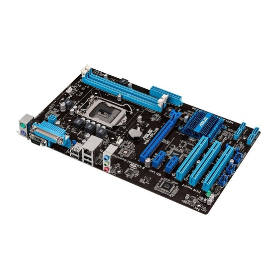
Page 19: Motherboard Layout
CPU_FAN DIGI +VRM ATX12V KB_USBPWB USB34 LAN_USB12 CHA_FAN BATTERY AUDIO H61-PLUS 64Mb BIOS 8111F PCIEX16 PCIEX1_1 1083 Intel ® PCIEX1_2 Super PCI1 PCI2 CLRTC PCI3 SATA3G_4 SATA3G_3 USBPWF SPDIF_OUT SB_PWR SATA3G_2 SATA3G_1 USB56 USB78 USB910 SPEAKER F_PANEL AAFP ASUS H61-PLUS... -
Page 20: Layout Contents
Contact your retailer immediately if the PnP cap is missing, or if you see any damage to the PnP cap/socket contacts/motherboard components. ASUS will shoulder the cost of repair only if the damage is shipment/ transit-related. -
Page 21: Cpu Installation
1.4.1 CPU installation The LGA1156 CPU is not compatible with the LGA1155 socket. DO NOT install an LGA1156 CPU on the LGA1155 socket. ASUS H61-PLUS... - Page 22 Chapter 1: Product introduction 1-10...
-
Page 23: Cpu Heatsink And Fan Assembly Installation
1.4.2 CPU heatsink and fan assembly installation Apply the Thermal Interface Material to the CPU heatsink and CPU before you install the heatsink and fan if necessary. To install the CPU heatsink and fan assembly ASUS H61-PLUS 1-11... - Page 24 To uninstall the CPU heatsink and fan assembly Chapter 1: Product introduction 1-12...
-
Page 25: System Memory
DDR2 DIMM socket. DDR3 modules are developed for better performance with less power consumption. The figure illustrates the location of the DDR3 DIMM sockets: Channel Sockets Channel A DIMM_A1 H61-PLUS Channel B DIMM_B1 H61-PLUS 240-pin DDR3 DIMM sockets ASUS H61-PLUS 1-13... -
Page 26: Memory Configurations
• For system stability, use a more efficient memory cooling system to support a full memory load (2 DIMMs) or overclocking condition. H61-PLUS Motherboard Qualified Vendors Lists (QVL) DDR3 2400 (O.C.) MHz capability DIMM socket Chip support (Optional) Vendors Part No. - Page 27 1.5V • • G.SKILL F3-14900CL9Q-8GBXL(XMP) 8GB(2GB x 4) 9-9-9-24 1.6V • • KINGSTON KHX1866C9D3T1K3/3GX(XMP) 3GB(3 x 1GB) 1.65V • • KINGSTON KHX1866C9D3K4/16GX(XMP) 16GB(4GB x 4) DS 1.65V • • KINGSTON KHX1866C9D3T1K3/6GX(XMP) 6GB(3 x 2GB) 1.65V • • ASUS H61-PLUS 1-15...
- Page 28 DDR3-1600 MHz capability DIMM socket Chip support (Optional) Vendors Part No. Size Chip NO. Timing Voltage Brand 1 DIMM 2 DIMMs 3CCD-1509A A-DATA AM2U16BC2P1 A-DATA • • EL1126T A-DATA AD31600E001GM(O)U3K 3GB(3 x 1GB) 8-8-8-24 1.65V-1.85V • 3CCD-1509A A-DATA AM2U16BC4P2 DS A-DATA •...
- Page 29 • • OCZ3X13334GK(XMP) 4GB(2 x 2GB) DS - 7-7-7-20 1.75V • • OCZ3G1333LV6GK 6GB(3 x 2GB) DS - 9-9-9-20 1.65V • • OCZ3P1333LV6GK 6GB(3 x 2GB) DS - 7-7-7-20 1.65V • • (continued on the next page) ASUS H61-PLUS 1-17...
- Page 30 DDR3-1333 MHz capability DIMM socket support Chip (Optional) Vendors Part No. Size Chip NO. Timing Voltage Brand 1 DIMM 2 DIMMs OCZ3X1333LV6GK(XMP) 6GB(3 x 2GB) DS - 8-8-8-20 1.60V • • OCZ3G1333LV8GK 8GB(2x 4GB) DS - 9-9-9-20 1.65V • • OCZ3RPR1333C9LV8GK 8GB(2x 4GB) DS -...
- Page 31 1 DIMM: Supports one module inserted into either slot as single-channel memory configuration. • 2 DIMMs: Supports one pair of modules inserted into both the blue slots as one pair of dual-channel memory configuration. Visit the ASUS website at www.asus.com for the latest QVL. ASUS H61-PLUS 1-19...
-
Page 32: Installing A Dimm
1.5.3 Installing a DIMM To remove a DIMM Chapter 1: Product introduction 1-20... -
Page 33: Expansion Slots
The PCI slot supports cards such as a LAN card, SCSI card, USB card, and other cards that comply with PCI specifications. 1.6.4 PCI Express 2.0 x1 slot This motherboard supports PCI Express 2.0 x1 network cards, SCSI cards, and other cards that comply with the PCI Express specifications. ASUS H61-PLUS 1-21... -
Page 34: Pci Express 3.0/2.0 X16 Slot
1.6.5 PCI Express 3.0/2.0 x16 slot This motherboard has a PCI Express 3.0/2.0 x16 slot that supports PCI Express 3.0/2.0 x16 graphic cards complying with the PCI Express specifications. PCIe 3.0 speed is supported by Intel 3rd generation Core™ processors. ®... -
Page 35: Jumpers
CLRTC Normal Clear RTC (Default) H61-PLUS Clear RTC RAM To erase the RTC RAM: Turn OFF the computer and unplug the power cord. Move the jumper cap from pins 1-2 (default) to pins 2-3. Keep the cap on pins 2-3 for about 5~10 seconds, then move the cap back to pins 1-2. - Page 36 H61-PLUS +5VSB (Default) H61-PLUS Keyboard and USB device wake-up USB device wake-up (3-pin USBPWF) Set this jumper to +5V to wake up the computer from S1 sleep mode (CPU stopped, DRAM refreshed, system running in low power mode) using the connected USB devices.
-
Page 37: Connectors
Rear Speaker Out Rear Speaker Out Lime (Rear panel) Line Out Front Speaker Out Front Speaker Out Front Speaker Out Pink (Rear panel) Mic In Mic In Bass/Center Bass/Center Lime (Front panel) – – – Side Speaker Out ASUS H61-PLUS 1-25... -
Page 38: Internal Connectors
H61-PLUS HD-audio-compliant Legacy AC’97 pin definition compliant definition H61-PLUS Front panel audio connector • We recommend that you connect a high-definition front panel audio module to this connector to avail of the motherboard’s high-definition audio capability. • If you want to connect a high-definition front panel audio module to this connector, set the Front Panel Type item in the BIOS setup to [HD]. - Page 39 The system may become unstable or may not boot up if the power is inadequate. • If you are uncertain about the minimum power supply requirement for your system, refer to the Recommended Power Supply Wattage Calculator at http://support.asus. com/PowerSupplyCalculator/PSCalculator.aspx?SLanguage=en-us for details. ASUS H61-PLUS 1-27...
- Page 40 S/PDIF Out module cable to this connector, then install the module to a slot opening at the back of the system chassis. H61-PLUS SPDIF_OUT H61-PLUS Digital audio connector The S/PDIF module is purchased separately. Chapter 1: Product introduction 1-28...
-
Page 41: Cpu And Chassis Fan Connectors
The two fan connectors support fans of maximum 2A (24 W) fan power. • Only the 4-pin CPU fan and 4-pin chassis fan support the ASUS Fan Xpert feature. USB connectors (10-1 pin USB56, USB78, USB910) These connectors are for USB 2.0 ports. Connect the USB module cable to any of these connectors, then install the module to a slot opening at the back of the system chassis. -
Page 42: System Panel Connector
PWR_BTN H61-PLUS PIN 1 +HDD_LED- RESET H61-PLUS System panel connector • System power LED (2-pin +PWR_LED-) This 2-pin connector is for the system power LED. Connect the chassis power LED cable to this connector. The system power LED lights up when you turn on the system power, and blinks when the system is in sleep mode. -
Page 43: Software Support
The contents of the Support DVD are subject to change at any time without notice. Visit the ASUS website at www.asus.com for updates. To run the Support DVD Place the Support DVD into the optical drive. - Page 44 Chapter 1: Product introduction 1-32...
-
Page 45: Chapter 2: Bios Information
BIOS in the future. Copy the original motherboard BIOS using the ASUS Update utility. 2.1.1 ASUS Update utility The ASUS Update is a utility that allows you to manage, save, and update the motherboard BIOS in Windows environment. ®... -
Page 46: Asus Ez Flash 2
Follow the onscreen instructions to complete the updating process. 2.1.2 ASUS EZ Flash 2 The ASUS EZ Flash 2 feature allows you to update the BIOS without using an OS-based utility. Before you start using this utility, download the latest BIOS file from the ASUS website at www.asus.com. -
Page 47: Asus Crashfree Bios 3 Utility
2.1.3 ASUS CrashFree BIOS 3 utility The ASUS CrashFree BIOS 3 is an auto recovery tool that allows you to restore the BIOS file when it fails or gets corrupted during the updating process. You can restore a corrupted BIOS file using the motherboard support DVD or a USB flash drive that contains the updated BIOS file. -
Page 48: Asus Bios Updater
2.1.4 ASUS BIOS Updater ASUS BIOS Updater allows you to update BIOS in DOS environment. This utility also allows you to copy the current BIOS file that you can use as a backup when the BIOS fails or gets corrupted during the updating process. -
Page 49: Updating The Bios File
Ensure to load the BIOS default settings to ensure system compatibility and stability. Select the Load Optimized Defaults item under the Exit menu. Refer to section 2.9 Exit menu for details. • Ensure to connect all SATA hard disk drives after updating the BIOS file if you have disconnected them. ASUS H61-PLUS... -
Page 50: Bios Setup Program
The BIOS setup screens shown in this section are for reference purposes only, and may not exactly match what you see on your screen. Visit the ASUS website at www.asus.com to download the latest BIOS file for this • motherboard. - Page 51 Advanced mode right hand side functions • The boot device options vary depending on the devices you installed to the system. The Boot Menu(F8) button is available only when the boot device is installed to the • system. ASUS H61-PLUS...
-
Page 52: Advanced Mode
The Advanced Mode provides advanced options for experienced end-users to configure the BIOS settings. The figure below shows an example of the Advanced Mode. Refer to the following sections for the detailed configurations. To access the EZ Mode, click Exit, then select ASUS EZ Mode. Back button Menu items... -
Page 53: Menu Items
You cannot select an item that is not user-configurable. A configurable field is highlighted when selected. To change the value of a field, select it and press <Enter> to display a list of options. ASUS H61-PLUS... -
Page 54: Main Menu
Main menu The Main menu screen appears when you enter the Advanced Mode of the BIOS Setup program. The Main menu provides you an overview of the basic system information, and allows you to set the system date, time, language, and security settings. 2.3.1 System Language [English] Allows you to choose the BIOS language version from the options. -
Page 55: Administrator Password
To clear the user password, follow the same steps as in changing a user password, but press <Enter> when prompted to create/confirm the password. After you clear the password, the User Password item on top of the screen shows Not Installed. ASUS H61-PLUS 2-11... -
Page 56: Ai Tweaker Menu
Ai Tweaker menu The Ai Tweaker menu items allow you to configure overclocking-related items. Be cautious when changing the settings of the Ai Tweaker menu items. Incorrect field values can cause the system to malfunction. The configuration options for this section vary depending on the CPU and DIMM model you installed on the motherboard. -
Page 57: Memory Frequency [Auto]
Allows you to enable or disable the Enhanced Intel SpeedStep Technology (EIST). ® [Disabled] Disables this function. [Enabled] The operating system dynamically adjusts the processor voltage and core frequency which may result in decreased average consumption and decreased average heat production. ASUS H61-PLUS 2-13... -
Page 58: Digi+ Vrm
Turbo Mode [Enabled] [Enabled] Allows processor cores to run faster than marked frequency in specific conditions. [Disabled] Disables this function. The first three items appear only when you set the Turbo Mode items to [Enabled]. Long Duration Power Limit [Auto] Allows you to limit the turbo ratio’s long duration power. -
Page 59: Cpu Voltage [Offset Mode]
To offset the voltage by a positive value. [–] To offset the voltage by a negative value. CPU Offset Voltage [Auto] Allows you to set the CPU Offset voltage. The values range from 0.005V to 0.635V with a 0.005V interval. ASUS H61-PLUS 2-15... -
Page 60: Dram Voltage [Auto]
CPU Manual Voltage [Auto] This item appears only when you set the CPU Voltage item to [Manual Mode] and allows you to set a fixed CPU voltage. The values range from 0.800V to 1.990V with a 0.005V interval. Refer to the CPU documentation before setting the CPU voltage. Setting a high voltage may damage the CPU permanently, and setting a low voltage may make the system unstable. -
Page 61: Advanced Menu
The Intel Hyper-Threading Technology allows a hyper-threading processor to appear as two logical processors to the operating system, allowing the operating system to schedule two threads or processes simultaneously. [Enabled] Two threads per activated core are enabled. [Disabled] Only one thread per activated core is enabled. ASUS H61-PLUS 2-17... - Page 62 Active Processor Cores [All] Allows you to choose the number of CPU cores to activate in each processor package. Configuration options: [All] [1] [2] [3] Limit CPUID Maximum [Disabled] [Enabled] Allows legacy operating systems to boot even without support for CPUs with extended CPUID functions.
-
Page 63: Pch Configuration
RTC wake timer at S3 entry. Configuration options: [Immediately] [1 minute] [2 minutes] [5 minutes] [10 minutes] [15 minutes] [30 minutes] [1 hour] [2 hours] Active Page Threshold Support [Disabled] Allows you to enable or disable the Active Page Threshold Support. Configuration options: [Enabled] [Disabled] ASUS H61-PLUS 2-19... -
Page 64: Sata Configuration
Active Memory Threshold [x] This item appears only when you set the Active Page Threshold Support to [Enabled] and allows you to set the Active Memory Threshold. When the partition size is larger than the Active Page Threshold size, the system will try to support the Intel(R) Rapid Start Technology. -
Page 65: Usb Configuration
Motherboard layout in this user manual for the locations of the USB ports. The USB port numbers may not be arranged in a consecutive order. 2.5.6 Onboard Devices Configuration HD Audio Controller [Enabled] [Enabled] Enables the High Definition Audio Controller. [Disabled] Disables the controller. ASUS H61-PLUS 2-21... -
Page 66: Serial Port Configuration
The following two items appear only when you set the HD Audio Controller item to [Enabled]. Front Panel Type [HD] Allows you to set the front panel audio connector (AAFP) mode to legacy AC’97 or high- definition audio depending on the audio standard that the front panel audio module supports. [HD] Sets the front panel audio connector (AAFP) mode to high definition audio. -
Page 67: Apm
<-> keys to adjust the time. - Hour / - Mimute / - Second Allows you to set the RTC alarm time. Use <+> and <-> keys to adjust the time. Use <+> and <-> keys to adjust the time. ASUS H61-PLUS 2-23... -
Page 68: Network Stack
2.5.8 Network Stack Network Stack [Disabled] This item allows user to disable or enable the UEFI network stack. Configuration options: [Disabled] [Enabled] The following two items appear only when you set the previous item to [Enabled]. Ipv4 PXE Support [Enabled] This item allows user to disable or enable the Ipv4 PXE Boot support. -
Page 69: Monitor Menu
The onboard hardware monitor automatically detects and displays the CPU and chassis fan speeds in rotations per minute (RPM). If the fan is not connected to the motherboard, the field shows N/A. Select Ignore if you do not wish to display the detected speed. ASUS H61-PLUS 2-25... -
Page 70: Cpu Q-Fan Control [Enabled]
2.6.3 CPU Q-Fan Control [Enabled] [Disabled] Disables the CPU Q-Fan control feature. [Enabled] Enables the CPU Q-Fan control feature. CPU Fan Speed Low Limit [200 RPM] This item appears only when you enable the CPU Q-Fan Control feature and allows you to disable or set the CPU fan warning speed. -
Page 71: Cpu Voltage, 3.3V Voltage, 5V Voltage, 12V Voltage
The onboard hardware monitor automatically detects the voltage output through the onboard voltage regulators. Select Ignore if you do not want to detect this item. 2.6.6 Anti Surge Support [Enabled] This item allows you to enable or disable the Anti Surge function. Configuration options: [Disabled] [Enabled] ASUS H61-PLUS 2-27... -
Page 72: Boot Menu
Boot menu The Boot menu items allow you to change the system boot options. Scroll down to display the following items: Chapter 2: Getting started 2-28... -
Page 73: Fast Boot [Enabled]
Accelerates the boot speed on the next boot after AC power loss. 2.7.2 Full Screen Logo [Enabled] [Enabled] Enables the full screen logo display feature. [Disabled] Disables the full screen logo display feature. Set this item to [Enabled] to use the ASUS MyLogo 2™ feature. ASUS H61-PLUS 2-29... -
Page 74: Bootup Numlock State [On]
POST Delay Time [3 sec] This item appears only when you set Full Screen Logo to [Enabled]. This item allows you to select the desired additional POST waiting time to easily enter the BIOS setup. You can only execute the POST delay time during Normal Boot. The values range from 0 to 10 seconds. This feature will only work under normal boot. -
Page 75: Security Boot
Allows you to immediately load the default Security Boot keys, Platform key (PK), Key- exchange Key (KEK), Signature database (db), and Revoked Signatures (dbx). The Platform Key (PK) state will change from Unloaded mode to Loaded mode. The settings are applied after reboot or at the next reboot. ASUS H61-PLUS 2-31... - Page 76 Key-exchange Key (KEK) refers to Microsoft Secure Boot Key database (KEK). ® Clear Secure Boot keys This item appears only when you load the default Secure Boot keys. This item allows you to clear all default Secure Boot keys. PK Management The Platform Key (PK) locks and secures the firmware from any non-permissible changes.
-
Page 77: Boot Option Priorities
• To select the boot device during system startup, press <F8> when ASUS Logo appears. • To access Windows OS in Safe Mode, press <F8> after POST. -
Page 78: Boot Override
2.7.11 Boot Override These items displays the available devices. The number of device items that appears on the screen depends on the number of devices installed in the system. Click an item to start booting from the selected device. Chapter 2: Getting started 2-34... -
Page 79: Tools Menu
<Enter> to display the submenu. 2.8.1 ASUS EZ Flash 2 Utility Allows you to run ASUS EZ Flash 2. Press [Enter] to launch the ASUS EZ Flash 2 screen. For more details, see section 2.1.2 ASUS EZ Flash 2. 2.8.2... -
Page 80: Exit Menu
This option allows you to exit the Setup program without saving your changes. When you select this option or if you press <Esc>, a confirmation window appears. Select Yes to discard changes and exit. ASUS EZ Mode This option allows you to enter the EZ Mode screen. Launch EFI Shell from filesystem device This option allows you to attempt to launch the EFI Shell application (shellx64.efi) from one of... -
Page 81: Appendices
Cet appareil est conforme aux normes CNR exemptes de licence d’Industrie Canada. Le fonctionnement est soumis aux deux conditions suivantes : (1) cet appareil ne doit pas provoquer d’interférences et (2) cet appareil doit accepter toute interférence, y compris celles susceptibles de provoquer un fonctionnement non souhaité de l’appareil. ASUS H61-PLUS... -
Page 82: Canadian Department Of Communications Statement
ASUS Recycling/Takeback Services ASUS recycling and takeback programs come from our commitment to the highest standards for protecting our environment. We believe in providing solutions for you to be able to responsibly recycle our products, batteries, other components as well as the packaging materials. -
Page 83: Asus Contact Information
+1-812-282-3777 +1-510-608-4555 Web site usa.asus.com Technical Support Telephone +1-812-282-2787 Support fax +1-812-284-0883 Online support support.asus.com ASUS COMPUTER GmbH (Germany and Austria) Address Harkort Str. 21-23, D-40880 Ratingen, Germany +49-2102-959911 Web site www.asus.de Online contact www.asus.de/sales Technical Support Telephone +49-1805-010923* Support Fax... - Page 84 Appendices...