Table of Contents
Advertisement
Quick Links
Advertisement
Table of Contents

Related Manuals for Asus H61M-C/SI


Summary of Contents for Asus H61M-C/SI
- Page 1 H61M-C...
- Page 2 INCIDENTAL, OR CONSEQUENTIAL DAMAGES (INCLUDING DAMAGES FOR LOSS OF PROFITS, LOSS OF BUSINESS, LOSS OF USE OR DATA, INTERRUPTION OF BUSINESS AND THE LIKE), EVEN IF ASUS HAS BEEN ADVISED OF THE POSSIBILITY OF SUCH DAMAGES ARISING FROM ANY DEFECT OR ERROR IN THIS MANUAL OR PRODUCT.
-
Page 3: Table Of Contents
Package contents ....................... xi Chapter 1: Product introduction Special features .................... 1-1 1.1.1 Product highlights ................1-1 1.1.2 ASUS Exclusive Features ............... 1-2 Before you proceed ..................1-4 Motherboard overview ................. 1-5 1.3.1 Placement direction ................ 1-5 1.3.2 Screw holes ..................1-5 1.3.3... - Page 4 Setup Mode [EZ Mode] ..............2-25 2.7.8 CSM (Compatibility Support Module) ..........2-25 2.7.9 Security Boot .................2-26 2.7.10 Boot Option Priorities ..............2-29 2.7.11 Boot Override ................2-29 Tools menu ....................2-30 2.8.1 ASUS EZ Flash 2 Utility ..............2-30 2.8.2 ASUS SPD Information ..............2-30...
- Page 5 ................. 2-30 Exit menu ....................2-31 Appendices Notices ........................A-1 ASUS contact information ..................A-3...
-
Page 6: Safety Information
Safety information Electrical safety • before relocating the system. • When adding or removing devices to or from the system, ensure that the power cables for the devices are unplugged before the signal cables are connected. If possible, disconnect all power cables from the existing system before you add a device. •... -
Page 7: About This Guide
Refer to the following sources for additional information and for product and software updates. ASUS websites The ASUS website provides updated information on ASUS hardware and software products. Refer to the ASUS contact information. Optional documentation that may have been added by your dealer. These documents are not part of the... - Page 8 Conventions used in this guide To ensure that you perform certain tasks properly, take note of the following symbols used throughout this manual. DANGER/WARNING: Information to prevent injury to yourself when trying to complete a task. CAUTION: Information to prevent damage to the components when trying to complete a task IMPORTANT: Instructions that you MUST follow to complete a task.
- Page 9 ® Turbo Boost Technology 2.0 The Intel ® Turbo Boost Technology 2.0 support depends on the CPU • types. ® Refer to www.asus.com for Intel CPU support list. • ® Chipset Intel H61 Express Chipset Memory 2 x DIMMs, max. 16GB, DDR3 2200 (O.C.) / 2133 (O.C.) / 2000 (O.C.) /...
- Page 10 BIOS features 64 Mb Flash ROM, UEFI BIOS, PnP, DMI v2.0, WfM 2.0, ACPI v2.0a, SM BIOS v2.7, SLP 3.0, Multi-language BIOS, ASUS EZ Flash 2, ASUS CrashFree BIOS 3, F12 PrintScreen function, F3 Shortcut function, and ASUS DRAM SPD (Serial Presence Detect) memory information...
-
Page 11: Package Contents
SATA3G_4 SATA3G_3 USB56 SPDIF_OUT USB78 USB910 SPEAKER AAFP ASUS H61M-C motherboard 2 x Serial ATA 3 Gb/s cables 1 x I/O Shield User Guide Support DVD • If any of the above items is damaged or missing, contact your retailer. -
Page 13: Chapter 1: Product Introduction
PCIe 1.0 and PCIe 2.0 devices. PCIe 3.0 will become a must-have feature for users who wish to them. ® * PCI 3.0 speed is supported by Intel 3rd generation Core™ processors. ASUS H61M-C... -
Page 14: Asus Exclusive Features
XP/Vista operating systems. Ai Charger Ai Charger is ASUS fast-charging software that supports iPod, iPhone, and iPad. * Check your USB mobile device if it fully supports the BC 1.1 function. ** The actual charging speed may vary with your USB device’s conditions. - Page 15 ASUS CrashFree BIOS 3 is an auto-recovery tool that allows you to restore a corrupted BIOS ASUS EZ Flash 2 ASUS EZ Flash 2 is a user-friendly utility that allows you to update the BIOS without using a C.P.R. (CPU Parameter Recall) The BIOS C.P.R.
-
Page 16: Before You Proceed
Before you proceed Take note of the following precautions before you install motherboard components or change any motherboard settings. • Unplug the power cord from the wall socket before touching any component. • Before handling components, use a grounded wrist strap or touch a safely grounded object or a metal object, such as the power supply case, to avoid damaging them due to static electricity. -
Page 17: Motherboard Overview
Screw holes Place six screws into the holes indicated by circles to secure the motherboard to the chassis. DO NOT overtighten the screws! Doing so can damage the motherboard. Place this side towards the rear of the chassis H61M-C ASUS H61M-C... -
Page 18: Motherboard Layout
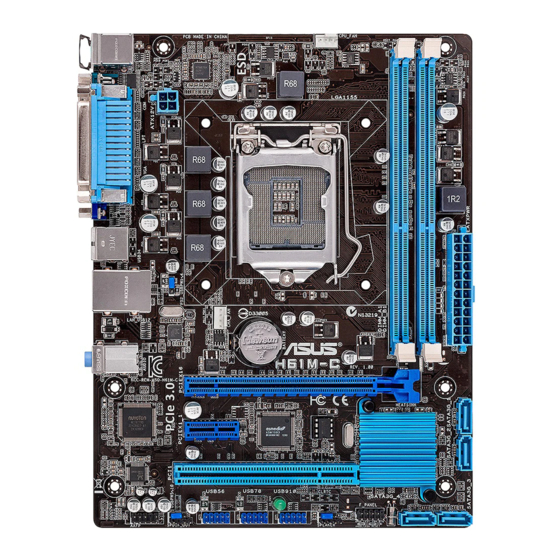
1.3.3 Motherboard layout 17.8cm(7.0in) KBMS CPU_FAN 8876 ATX12V USB34 LAN_USB12 CHA_FAN 8111F BATTERY AUDIO H61M-C PCIEX16 Super 64Mb PCIEX1_1 BIOS 1083 ® Intel PCI1 SB_PWR F_PANEL SATA3G_4 SATA3G_3 USB56 USB78 USB910 SPDIF_OUT SPEAKER AAFP 13 12 10 9 Chapter 1: Product introduction... -
Page 19: Layout Contents
Contact your retailer immediately if the PnP cap is missing, or if you see any damage to the PnP cap/socket contacts/motherboard components. ASUS will shoulder the cost of repair only if the damage is shipment/ transit-related. -
Page 20: Cpu Installation
1.4.1 CPU installation The LGA1156 CPU is not compatible with the LGA1155 socket. DO NOT install an LGA1156 CPU on the LGA1155 socket. Chapter 1: Product introduction... - Page 21 ASUS H61M-C...
-
Page 22: Cpu Heatsink And Fan Assembly Installation
1.4.2 CPU heatsink and fan assembly installation Apply the Thermal Interface Material to the CPU heatsink and CPU before you install the heatsink and fan if necessary. To install the CPU heatsink and fan assembly 1-10 Chapter 1: Product introduction... - Page 23 To uninstall the CPU heatsink and fan assembly ASUS H61M-C 1-11...
-
Page 24: System Memory
System memory 1.5.1 Overview This motherboard comes with two Double Data Rate 3 (DDR3) Dual Inline Memory Modules (DIMM) sockets. A DDR3 module has the same physical dimensions as a DDR2 DIMM but is notched differently to prevent installation on a DDR2 DIMM socket. DDR3 modules are developed for better performance with less power consumption. -
Page 25: Installing A Dimm
To operate at the vendor-marked or at a higher frequency, refer to section 2.4 Ai Tweaker menu for manual memory frequency adjustment. memory load (2 DIMMs) or overclocking condition. 1.5.3 Installing a DIMM ASUS H61M-C 1-13... -
Page 26: Expansion Slots
To remove a DIMM Expansion slots In the future, you may need to install expansion cards. The following sub-sections describe the slots and the expansion cards that they support. Unplug the power cord before adding or removing expansion cards. Failure to do so may cause you physical injury and damage motherboard components. -
Page 27: Pci Slot
– – – – shared HD audio – – – – – – shared – SATA controller 1 – – – shared – – – – SATA controller 2 – – – shared – – – – ASUS H61M-C 1-15... -
Page 28: Jumpers
Jumpers Clear RTC RAM (3-pin CLRTC) This jumper allows you to clear the Real Time Clock (RTC) RAM in CMOS. You can clear the CMOS memory of date, time, and system setup parameters by erasing the CMOS RTC RAM data. The onboard button cell battery powers the RAM data in CMOS, which include system setup information such as system passwords. - Page 29 H61M-C USB device wake-up • The USB device wake-up feature requires a power supply that can provide 500mA on • The total current consumed must NOT exceed the power supply capability (+5VSB) whether under normal condition or in sleep mode. ASUS H61M-C 1-17...
-
Page 30: Connectors
Connectors 1.8.1 Rear panel ports PS/2 Mouse port. This port connects to a PS/2 mouse. Parallel port. This 25-pin port connects a parallel printer, a scanner, or other devices. LAN (RJ-45) port. This port allows Gigabit connection to a Local Area Network (LAN) through a network hub. -
Page 31: Internal Connectors
Front Panel Type item in the BIOS setup to [HD]. If you want to connect an AC'97 front panel audio module to this connector, set the item to [AC97]. By default, this connector is set to [HD]. See section details. ASUS H61M-C 1-19... - Page 32 • If you are uncertain about the minimum power supply requirement for your system, refer to the Recommended Power Supply Wattage Calculator at http://support.asus. com/PowerSupplyCalculator/PSCalculator.aspx?SLanguage=en-us for details. 1-20 Chapter 1: Product introduction...
- Page 33 This connector is for an additional Sony/Philips Digital Interface (S/PDIF) port. Connect the S/PDIF Out module cable to this connector, then install the module to a slot opening at the back of the system chassis. H61M-C SPDIF_OUT H61M-C Digital audio connector The S/PDIF module is purchased separately. ASUS H61M-C 1-21...
- Page 34 The two fan connectors support fans of maximum 2A (24 W) fan power. • Only the 4-pin CPU fan and 4-pin chassis fan support the ASUS Fan Xpert feature. USB connectors (10-1 pin USB56, USB78, USB910) These connectors are for USB 2.0 ports. Connect the USB module cable to any of these connectors, then install the module to a slot opening at the back of the system 480 Mbps connection speed.
- Page 35 Speaker connector (4-pin SPEAKER) The 4-pin connector is for the chassis-mounted system warning speaker. The speaker allows you to hear system beeps and warnings. SPEAKER H61M-C PIN 1 H61M-C Speaker out connector ASUS H61M-C 1-23...
-
Page 36: Software Support
The contents of the Support DVD are subject to change at any time without notice. Visit the ASUS website at www.asus.com for updates. To run the Support DVD Place the Support DVD into the optical drive.