Table of Contents
Advertisement
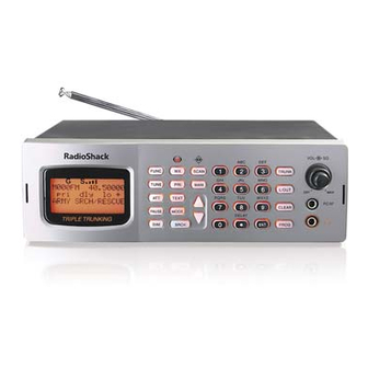
Thank you for purchasing your Triple Trunking Mobile / Base Radio Scanner
from RadioShack. Your scanner scans conventional frequencies and
trunked systems. Please read this user's guide before installing, setting up
and using your new scanner.
What's Included
Scanner
Mounting bracket
Lock washer (2)
AC adapter
Preprogrammed Frequency Addendum
Triple Trunking
Mobile / Base Radio Scanner
Antenna
DIN sleeve and keys (2) Rubber washer (2)
Rubber feet (3)
DC cable with fuse
www.radioshack.com
Screw (2)
Knob (2)
User's Guide
20-163
Advertisement
Table of Contents

Related Manuals for Radio Shack 20-163


Summary of Contents for Radio Shack 20-163
- Page 1 20-163 Triple Trunking Mobile / Base Radio Scanner Thank you for purchasing your Triple Trunking Mobile / Base Radio Scanner from RadioShack. Your scanner scans conventional frequencies and trunked systems. Please read this user’s guide before installing, setting up and using your new scanner.
-
Page 2: Table Of Contents
Contents Your Scanner ...............4 Installing Your Scanner ............7 Setting Up a Mobile Base ............7 Bracket Mounting .................7 Dashboard Installation ..............8 Connecting the Antenna ..............9 Powering Your Scanner ..............10 Headphones and Speakers ............12 Keytones and Brightness ............12 Delay ....................13 Squelch and Attenuator .............13 Scanner Setup ..............14 Defining a Channel ..............15 Copying a Frequency ..............16 Deleting Saved Frequencies ............17 CTCSS AND DCS ................17 Scanner Cloning ................18 Searching .................19 Seek Search .................19 Search Banks ................19 Zeromatic . - Page 3 Contents Monitoring ................30 Trunking Setup ..............31 Defining a Trunking Bank ............31 Trunking Modes ................32 Motorola Trunking Setup ............32 Base and Offset Frequencies .............34 EDACS Trunking Setup ..............35 LTR Trunking Setup ..............36 Searching for Talk Group IDs .............36 Saving a Talk Group ID ...............37 Deleting Talk Group IDs .............38 Saving Trunking Channels ............39 Trunk Scanning ..............39 Trunking Delay ................40 Locking Out Talk Group IDs ............41 Turning Off Sub-Banks ..............41 Talk Group ID Hold ..............42 Scanner Maintenance ............42 Text Tags ..................43 Troubleshooting ................45 Birdie Frequencies ..............46 Initializing the Scanner ...............47 Service and Repair ..............47 Scanning Legally .................48...
-
Page 4: Your Scanner
Your Scanner Mounting bracket DIN sleeve and keys (2) DC cable w/fuse AC adapter Knob (2) Rubber washer (2) Antenna Lock washer (2) Screw (2) Rubber foot (3) - Page 5 1-9 / A-Z– Numbers TRUNK — Accesses Squelch and letters. Zero enters trunking functions. VOLUME special characters. L/OUT – Locks out / OFF ./DELAY – Decimal channels, frequencies, point, space, delay or Talk Group IDs. functions. CLEAR ENT – Enter. PROG – Program. FUNC — Function. TUNE – Enters Tune mode. ATT – Attenuator. PAUSE DIM – Dimmer. — Weather search and Skywarn. PRI – Priority. TEXT – Activates text buttons. MODE – Changes receive mode. — Signal Stalker. SCAN — Starts a scan. MAN — Manually select a channel or enter a channel number. SRCH – Search. – Navigates functions.
- Page 6 DC 13.8V Connect power source. EXT SP Connect an external speaker. SCREW HOLE Use to mount the scanner in a car. Connect the supplied antenna or an external antenna. Seek Search Activate...
-
Page 7: Installing Your Scanner
Installing Your Scanner You can mount your triple trunking scanner in your vehicle or use it as a base station. Setting Up a Mobile Base You can place your scanner on a desk, shelf, or table to use it as a base station. Because the speaker is on the bottom of the scanner, you can use the mounting bracket to elevate your scanner off the surface for better sound. To you use the scanner on a flat surface: . Attach the three protective rubber feet to the mounting bracket. Do not use them if you are mounting the bracket with screws. 2. Slide the scanner into the bracket, aligning the scanner’s side holes with the holes in the bracket, and then screw the mounting knobs into the scanner. Bracket Mounting You can mount your scanner under or on top of the dashboard a desk, shelf, table or other flat surface, using the mounting bracket. 1. Use the supplied mounting bracket as a template to mark positions for the two mounting screws. -
Page 8: Dashboard Installation
3. Remove the paper backing from each washer and stick one inside of each bracket’s ear, aligning the washer’s hole with the bracket’s hole. 4. Attach the mounting bracket to your vehicle’s surface using the supplied screws and lockwashers. Dashboard Installation If you are unsure how to install your scanner in your vehicle, consult your automobile manufacturer, dealer, or a qualified installer. To mount in your dashboard, you must connect an external antenna and speaker. 1. Before installing, confirm your scanner fits in the desired mounting area and you have all the necessary materials. Your scanner requires a 2 x 7... -
Page 9: Connecting The Antenna
To remove your scanner from the DIN sleeve, insert the two keys straight into the scanner’s front panel and pull the scanner out. Connecting the Antenna To connect an external antenna, always follow the installation instructions supplied with the antenna. Use 50-ohm, RG-58, or RG-8, coaxial cable. If the antenna is over 50 feet from the scanner, use RG- 8 low-loss dielectric coaxial cable. If necessary, RadioShack carries a variety of adapters. To attach the supplied antenna: 1. Align the antenna slots with the tabs on the scanner, and slide the antenna into place. 2. Turn and push down until the antenna locks into place. Warning: Use extreme caution when installing or removing an outdoor antenna. If the antenna starts to fall, let it go! It could contact overhead power lines. If the antenna touches a power line, touching the antenna, mast, cable, or guy wires can cause electrocution and death. Call the power company to remove the antenna. DO NOT attempt to do so yourself. -
Page 10: Powering Your Scanner
Powering Your Scanner You can power your scanner from a wall outlet, or from your vehicle’s battery. You must use a power source that supplies 12V DC and delivers at least 600 mA. Its center tip must be set to positive and its plug must fit the scanner’s DC 13.8V jack. The supplied AC adapter and DC power cord meet these specifications. - Page 11 Vehicle (Power Socket) To power your scanner from a 12V power source in your vehicle, such as a cigarette-lighter socket, you need a 12V, 600 mA DC cigarette- lighter adapter (not supplied), available at your local RadioShack store. 1. Insert the adapter’s barrel plug into the scanner’s DC 13.8V jack. 2. Plug the adapter’s other end into your vehicle’s cigarette lighter or power socket. When you use a cigarette-lighter adapter, you might hear electrical noise from your engine while scanning. This is normal. Vehicle (Direct) 1. Disconnect the cable from your vehicle battery’s negative (-) terminal. . Ground the black wire of the supplied DC power cord to your vehicle’s chassis. The grounding screw must make complete contact with your vehicle’s metal frame.
-
Page 12: Headphones And Speakers
Headphones and Speakers You can plug headphones or speaker (neither included) into your scanner. To use headphones, connect the plug into the headphone jack on the front panel. Headphones automatically mute the scanner’s speaker. To use external speaker, connect the plug into the EXT SP jack on the rear panel. Even though some earphones/headphones let you hear some outside sounds when listening at normal volume levels, they still can present a traffic hazard. To protect your hearing, follow these earphone or headphones guidelines: • Do not listen at extremely high volume levels. Extended high- volume listening can lead to permanent hearing loss. • Set the volume to the lowest setting before listening. Turn on the scanner, and adjust the volume to a comfortable level. • After you set the volume, do not increase it. Over time, your ears adapt to the volume level, so a volume level that does not cause discomfort might still damage your hearing. • Do not wear headphones while driving. This can create a traffic hazard and is illegal in some areas. -
Page 13: Delay
To set the keytone: 1. Turn on the scanner. “Multi-system Trunking Scanner” appears. 2. While “Multi-system Trunking Scanner” appears, press 1 to turn on the keytone or 2 to turn it off. To change the backlight mode: Repeatedly press DIM to adjust display backlight brightness from Dark, Light off, or Light. Delay Sometimes, several seconds can pass between transmissions. To avoid missing a reply, a delay is automatically set for each channel. The scanner stops for 2 seconds after a transmission stops before it resumes scanning or searching. To turn the delay on / off: 1. Press ./DELAY. DLY appears if the delay is on. 2. To turn on the delay, press ./DELAY again. “dly” appears if the delay is off. Squelch and Attenuator The squelch and attenuator control the scanner sensitivity. If you hear a hissing sound, the scanner will remain on the current channel. To set squelch: 1. Turn off the scanner and turn SQUELCH fully counterclockwise. -
Page 14: Scanner Setup
With the attenuator on, the scanner might not receive weak signals. You can reduce interference using two attenuator modes: • Global – (Default) The attenuator setting is applied to all channels, bands, or groups. • Normal – Lets you set the attenuator in each channel, band, or group. You cannot set the attenuator while scanning. To set the attenuator mode: 1. To set Global mode, press FUNC and then ATT. On the display “G” appears.” 2. To set the attenuator for each channel, press FUNC and then ATT. On the display “G” disappears. For each channel: • On – Press ATT. “A” appears. • Off – Press ATT again. “A” disappears.” Scanner Setup A frequency, expressed in kHz or MHz, is the tuning location of a station. Your scanner saves frequencies to channels and groups the channels into banks. The scanner’s 10 banks each hold 100 channels (1,000 channels total). The scanner is preset to the most common AM or FM receive modes for each frequency range. However, some amateur transmissions may operate in a different mode. If the transmission sounds weak or distorted, you may have the channel set to the wrong receive mode: AM –... -
Page 15: Defining A Channel
FM – Frequency Modulation, used for most public safety transmissions, broadcast, business, and amateur radio transmissions. CT – FM transmissions with Continuous Tone Coded Squelch System (CTCSS) DC – FM transmissions with Digital Coded Squelch (DCS) MO – Motorola Trunking System ED – EDACS Trunking System LT – LTR Trunking System If you change the receive mode using MODE key, the scanner shows the receive mode for small caps (ex. fm, am, ct, or dc). If you want to change the default setting, press FUNC then press MODE. -
Page 16: Copying A Frequency
6. If necessary, press MODE to change the receiving mode. 7. Press ENT. If the frequency is already stored in the bank, “Dupl.Freq. ChXXX” appears. To copy the duplicate frequency anyway, press ENT or press CL to cancel. If you made a mistake in Step 5, “Invalid Freq.” briefly appears and the scanner beeps when you press ENT. Go back to step 5 again. 8. Press MAN again. M and the bank and channel number appear. For information about adding text tags to a channel or bank, see “Text Tags” on Page 43. Copying a Frequency When you copy a frequency, all the channel conditions, including mode, are also copied. -
Page 17: Deleting Saved Frequencies
Deleting Saved Frequencies To delete a saved frequency: 1. Press MAN. 2. Use the number keys to enter the frequency’s channel number. 3. Press MAN. 4. Press PROG. M changes to P. 5. Press FUNC. 6. Press CL. “0.0000” appears. To delete all saved frequencies in a bank: 1. Press PROG. M changes to P. 2. Press FUNC. 3. Use the number keys to enter the bank number. 4. Press FUNC then CL. “Clear entire bank?” appears. 5. Press 1 to clear all. Any other key aborts. CTCSS AND DCS CTCSS and DCS allow multiple users to share a single radio frequency without hearing each other’s transmissions. Your scanner features an advanced, CTCSS and DCS decoder that displays CTCSS... -
Page 18: Scanner Cloning
5. Press FUNC, then MODE. 6. Use the or to select the desired CTCSS or DCS code. You can enter the code manually. The scanner automatically fills in the code. See Appendix B for a list of codes. 7. Press ENT. To save a CTCSS or DCS code: Press ENT while the code appears. Scanner Cloning You can transfer the programmed data to and from another PRO-163 (or PRO-164) scanner using a connecting cable which has 1/8-inch stereo (TRS) phone plugs on both ends (not supplied). You can also upload or download the programmed data to or from a PC using an optional USB cable and application software available through your local RadioShack store. The application software is also... -
Page 19: Searching
Searching You can search for transmissions using the preprogrammed search bank, which is divided into eight search bands. Seek Search When Seek Search is active, the scanner stops on active frequencies for five seconds and then resumes searching automatically. To activate Seek Search: 1. Press FUNC then 7. “Seek Search ON” appears briefly and “S” appears on the display. 2. To turn off Seek Search, press FUNC then 7 again. “Seek Search OFF” appears briefly. Search Banks To search preprogrammed search banks: 1. Press SRCH repeatedly to select a bank. - Page 20 SR3 to SR5 banks contain several groups. To turn off a group, press the group number; the group number disappears. To turn the group back on, press the group number again. 2. Adjust the Squelch. After the set delay, the scanner starts searching. When the scanner finds an active frequency, it stops searching. 3. To pause while searching, press PSE. The scanner stops searching and *** PAUSED *** appears. To resume, press PSE again. 4. If the scanner stops on an unwanted frequency, you can press L/OUT to lock out the frequency. In the SR6 Railraod and SR7 Limit search bands, press FUNC then or to start searching up from the lowest or down from the highest frequency. To search banks SR0-SR2: 1. Press SRCH repeatedly to select SR0, SR1, or SR2. 2. To search the entire band, press FUNC then SRCH. “MAN” (Manual select) or “SRCH” (searches through the band) appears. The scanner starts searching and “SRCH” appears on the display. When the scanner finds an active frequency, it stops searching. Press FUNC then SRCH again to return to the previous mode.
-
Page 21: Zeromatic
Zeromatic While searching, the scanner stops if a transmission triggers the squelch setting. A narrow-band FM transmission can have a deviation of +/- 5 KHz, and the actual total bandwidth, including the tails of the sidebands, can be even greater. However, search intervals smaller than that can stop your scanner short of the correct (center) frequency. The Zeromatic function allows the scanner to find the correct center frequency for search banks SR3, SR4, SR5, SR6 and SR7. Zeromatic automatically tunes the step-increment frequency closest to the center frequency. To activate Zeromatic: 1. Press FUNC then 0. “Zeromatic ON.” appears briefly, then ZM appears. 2. To turn Zeromatic off, press FUNC then 0 again. “ZM” changes to “zm.” Programming a Search Range To program the search range of Bank SR7: 1. Repeatedly press SRCH to select SR7. -
Page 22: Signal Stalker Ii
6. Press SRCH to start searching. 7. Adjust the Squelch. After the set delay, the scanner starts searching. When the scanner finds an active frequency, it stops searching. Signal Stalker II Signal Stalker II provides a powerful tool to rapidly detect, monitor and save frequencies of nearby or high-power transmissions. Signal Stalker II resembles more expensive portable frequency counters, but provides many advantages over typical portable frequency counters. Signal Stalker II is more sensitive than portable frequency counters and will detect transmissions at a greater distance. Signal Stalker II rapidly searches the RF spectrum in 1 MHz segments. If it detects a signal, Signal Stalker II searches in finer steps until the signal source is found. Signal Stalker II can search all frequencies, or you can define frequency ranges, to avoid ranges with constant activity, such as paging or broadcast transmitters. -
Page 23: Locking Out Frequencies
Special Signal Stalker Special Signal Stalker II divides the frequency range by 1 MHz segments. If you lock out 5 frequencies within 1 MHz segment, the scanner will skip that segment in subsequent sweeps. To use Special Signal Stalker II: 1. Press FUNC. 2. Use or to select “Sp. Stalker” appears for Special Signal Stalker II. 3. To turn off Special Signal Stalker II, press FUNC and then or again. Locking Out Frequencies When you lock out frequencies during a search, the scanner continues searching, but ignores the locked out frequencies. You can lock out up to 50 frequencies in each bank. If you try to lock out more, “L/O Memory Full!” appears. While using Signal Stalker II, you can lock out 150 frequencies if searching all bands and 50 frequencies while searching PubSafety frequencies. If you lock out 5 frequencies within a 1 MHz segment, the scanner will skip that segment in subsequent sweeps. If you lock out all the frequencies in a search bank and only that search bank is activated, “All ranges Locked out!”... -
Page 24: Saving Found Frequencies
To review and unlock frequencies: 1. Press SRCH to enter search mode. 2. Press FUNC then L/OUT. The first locked-out frequency and lockout list appear. If the search bank has no locked-out frequencies, “No Lockout” appears. 3. Press or to review the list. The current position and the total locked-out number also appear as “Lockout XX of YY.” (Example: Lockout 10 of 30.) 4. (Optional) To unlock a frequency, select the frequency then press 5. Press FUNC then L/OUT again to exit. To unlock all frequencies in a search bank: 1. Press SRCH. 2. Select the search bank. 3. Press FUNC then press L/OUT. The Lockout list appears. 4. Press FUNC then 6. “Clear entire list?” appears. 5. Press 1. “List cleared” appears. Pressing any other key cancels the clearing. -
Page 25: Scanning
Scanning Scanning sequentially checks all saved channels for activity. You must save frequencies into channels to scan. The scanner does not scan empty channels or unsaved frequencies. You can increase the scanning speed by locking out channels with continuous transmissions, such as a weather channel or turning off entire banks. Turning off a bank prevents the scanner from scanning any channels within the bank. You cannot turn off all banks. There must be at least one active bank to scan. To scan: 1. Press SCAN. The scanner checks all unlocked channels in the active banks. To change the scan direction, press or . 2. To stop on a channel, press PSE. 3. To lock out a channel, when the scanner stops on the channel, press L/OUT. . To turn off a bank, press the bank’s number so the bank’s number disappears. To turn on a bank, press the number key so the bank’s number appears. Locking Out Channels You can increase the scanning speed by locking out channels with continuous transmissions. To locked out a channel: 1. Press MAN. 2. Enter the bank and channel number or use or to select the channel. 3. Press L/OUT. “lo” changes to “LO.” 4. To unlock a locked-out channel, press L/OUT again. -
Page 26: Priority Scanning
To review all locked out channels: 1. Press MAN. 2. Repeatedly pressing FUNC and then L/OUT to view each locked- out channel. 3. To unlock a channel, press L/OUT. “LO” changes to “lo.” 4. When you finish reviewing locked-out channels, press MAN. You can manually select any channel in a bank, even in turned- off banks. Priority Scanning In addition to the 1,000 programmable memory channels, your scanner has one Priority channel. When Priority is turned on, the scanner checks the Priority channel every 2 seconds. This lets you scan without missing a transmission on the Priority channel. -
Page 27: Weather Alerts
To modify the Priority channel: 1. Press PROG. 2. Press PRI. 3. Use the number keys to enter the frequency. 4. Press ENT. If the frequency is incorrect, “Invalid Freq” appears briefly. Weather Alerts The Federal Communications Commission (FCC) has allocated channels for use by the National Oceanic and Atmospheric Administration (NOAA). NOAA broadcasts Specific Area Message Encoding (SAME) alerts that include digitally encoded data about the severity of the alert. Regulatory agencies in other countries have also allocated channels for use by their weather reporting authorities. -
Page 28: Same Standby Mode
SAME Standby Mode SAME alerts include FIPS codes to identify areas, established by the US Census bureau. You can set your scanner to alert for all areas or limit weather alerts to up to 10 specific areas by FIPS code. The National Weather Service maintains a current list of FIPS codes at www.nws.noaa.gov/nwr/. To program a FIPS code: 1. Press WX and listen to identify the weather station with the strongest signal. 2. Press FUNC, and then PROG to access the FIPS code entry table. 3. Use or to select the desired FIPS code storage location. - Page 29 To review stored FIPS codes: 1. Press WX then a number key. 2. Press L/OUT to change the lockout status. For information about adding text tags to a FIPS code, see “Text Tags” on Page 43. To enter SAME standby: 1. Press FUNC, and then WX. The scanner will monitor the selected weather radio station for alerts with FIPS codes that match the codes you entered in the FIPS entry table. 2. To exit SAME standby, press FUNC, and then WX. The scanner searches the weather frequencies while in SAME standby mode when squelch is off.
-
Page 30: Skywarn
Skywarn Skywarn is an organized group of trained weather observers. Using Skywarn, you can hear trained observers in your area call in official reports to a control station that relays those reports to NOAA and other emergency agencies. Before using this feature, save local Skywarn frequencies for your area into Channel 999. To use Skywarn: Hold the Skywarn button ( ). “SKY” appears. If the skywarn channel is empty, “Not programmed” appears. Monitoring When monitoring, the scanner remains on a single channel. Your scanner features a power save circuit that allows the scanner to “sleep” briefly while waiting for a call on a monitored channel. -
Page 31: Trunking Setup
tune direction, press or . When the scanner finds an active frequency, it stops. 4. Press PSE to monitor the frequency. The transmission signal level is indicated by the 5 dots. To set a default tuning frequency: 1. Press MAN. 2. (Optional) Use the number keys to enter the frequency number. 3. Press FUNC, then TUNE. The scanner saves the frequency. For example, if you save 145.31000 MHz, when you press TUNE, the scanner starts tuning at 145.31000 MHz. Trunking Setup Instead of transmitting on a specific frequency, trunking systems choose one of several frequencies during a 2-way radio transmission and simultaneously transmit a Talk Group ID that identifies the 2-way radio user. This allows trunking systems to allocate fewer frequencies... -
Page 32: Trunking Modes
3. Repeatedly press MODE to select a trunking mode (Motorola, EDACS, or LTR). 4. Press PROG. Trunking Modes In Closed mode, the scanner stops only on transmissions with saved and unlocked Talk Group IDs. This lets you focus a scan on the frequencies you have identified, ignoring other transmissions. In Open mode, the scanner stops for transmissions on any unlocked channel. This lets you search for Talk Group IDs that you can then save. While scanning, “–” appears for Closed mode and “+” appears for Open mode under the channel storage bank’s number. When the scanner stops on a channel,”OPEN” or “CLOSED” appears. To set Open or Closed mode for a bank: 1. Press MAN. 2. Use or to select a bank. 3. Press FUNC then DELAY. “Bank OPEN” or “Bank CLOSED” appears. Motorola Trunking Setup Motorola systems can allocate as few as five frequencies to up to several thousand groups of users in three categories: •... - Page 33 Fleet Maps For Motorola Type I and hybrid systems, you must program a fleet map before saving Talk Group IDs. To program a fleet map: 1. Press PROG then TRUNK. 2. Press FUNC, then press or to select the bank. 3. If necessary, repeatedly press MODE to select “Motorola.” 4. Press FUNC, then press 8. “Size Code Setting” appears, with Block 0 selected. 5. Enter the size code for Block 0, supplied with the Type I system information, or try one of the following common fleet maps. Size BLOCKS Codes...
-
Page 34: Base And Offset Frequencies
For Motorola Type II, enter 15. 6. Press ENT. The next block appears. 7. Repeat steps 5-6 for each block. If you make a mistake, press CL and enter the correct size code. Base and Offset Frequencies To receive Motorola VHF and UHF system transmissions, you must program applicable base and offset frequencies. In the 800 MHz trunking band, you can select a base frequency (normal or offset), but in the 900 MHz trunking band, you do not need to set the base frequency. You can get information about base and offset frequencies from www.trunkscanner.com. UHF-Lo (406-512 MHz) To program Motorola base and offset frequencies: 1. Press PROG then TRUNK to enter the ID program mode. 2. Press FUNC, then press or . The bank number increases or decreases by one. If you hold down or , the bank number increases or decreases continuously. 3. If necessary, repeatedly press MODE to select “Motorola.” 4. Press FUNC then 2. The screen displays the Base, Offset, and Step with the B in Base blinking. -
Page 35: Edacs Trunking Setup
7. While the S in Step blinks, repeatedly press or to select the step number: 5.0, 6.25, 10.0, 12.5, 15.0, 18.75, 20.0, 25.0, 30.0, 31.25, 35.0, 37.5, 40.0, 43.75, or 50.0 kHz, then press ENT. . Press PROG. UHF-Hi (806-960 MHz) To program 800 MHz Motorola trunking: 1. Press PROG then TRUNK to enter the ID program mode. 2. Press FUNC, then press or . The bank number increases or decreases by one. If you hold down or , the bank number increases or decreases continuously. 3. If necessary, repeatedly press MODE to select “Motorola.” 4. Press FUNC then 3. NORMAL appears. 5. Press or to select NORMAL or SPLINTER and press ENT. If you are uncertain about the base frequency, use NORMAL. The base frequency in NORMAL is 851.0125 MHz. The base frequency in SPLINTER is 851.0000 MHz. . If you cannot receive with the NORMAL setting, change to SPLINTER. EDACS Trunking Setup EDACS (GE/Ericsson) systems transmit Talk Group ID data on a dedicated control channel. Scanning requires clear reception of the control channel at all times, so EDACS systems generally have a smaller usable area. You can manually select the data channel, but an external antenna can greatly improve EDACS scanning. If you are programming frequencies for an EDACS system, you must store them in the Logical Channel Number order (usually listed as LCN#). -
Page 36: Ltr Trunking Setup
LTR Trunking Setup LTR systems, assign each frequency a Home Repeater (HR) number, and are frequently programmed with unique ID codes for each radio. LTR Talk Group IDs are organized in a specific order, and to scan, you must program the frequencies in HR order. LTR systems are used primarily by businesses, such as taxicabs, delivery trucks, and repair services. LTR systems use a Home Repeater as part of their Talk Group ID. To save a correct Home Repeater: 1. Save the LTR channels in any order. 2. Set the bank to Open mode. 3. Manually select LT channels and watch the LTR data on the display. Your scanner displays the LTR Talk Group ID and a number preceded by “R.” The “R” number is the Home Repeater number for the transmission. 4. The assigned Home Repeater channel must equal the Home Repeater number. For example, R12 must be programmed into Channel 12. -
Page 37: Saving A Talk Group Id
To search for Talk Group IDs: 1. Set the bank to Open mode. 2. Press SCAN. The scanner scans through all unlocked channels in the active banks. 3. When the scanner stops on a transmission, press TRUNK. The scanner displays the ID location: Sub-bank. ID Location 00-29 Example: 2-01 If the ID has already been saved, “ID was saved” appears. If you try to store more than 150 talk group IDs in a bank, “Memory Full!”... -
Page 38: Deleting Talk Group Ids
. Use the number and decimal point keys to enter the Talk Group For ED Talk Group IDs, you can enter either a decimal or AFS code. The default setting is decimal ID entry. To use the AFS code, press FUNC then 2, “AFS Format” appears for about 2 seconds. You can then enter the AFS code. If you make a mistake, “Invalid ID value” appears when you press ENT. Go back to Step 3. If you entered an ID that is already stored in same bank, “Dupl. ID of X-XX appears.” To store the ID code, press ENT. To cancel, press CL. 7. Press ENT. For information about adding text tags to a Talk Group ID, see “Text Tags” on Page 43. Deleting Talk Group IDs You can delete an individual Talk Group ID or all Talk Group IDs in a bank. To delete a Talk Group ID: 1. Press PROG then TRUNK. -
Page 39: Saving Trunking Channels
5. To clear the Talk Group IDs, Press 1. To cancel the deletion, press any key except 1. Saving Trunking Channels Trunking channels are defined using the same procedure for non- trunking channels. In each bank, you can mix channel modes, including conventional, but you can scan only one trunking mode at a time, either EDACS, Motorola, or LTR. Because Motorola control frequencies change daily, you should save all the control frequencies in the same bank. If you do not know the control frequency, save all the Motorola frequencies in the same bank. EDACS frequencies are assigned Logical Channel Numbers (LCN) and organized in a specific order. To scan correctly, you must program the frequencies in LCN order, starting with Memory 01. Trunked modes (MO, ED, and LT) can only be selected for frequencies above 137 MHz that use trunking operations. -
Page 40: Trunking Delay
For Motorola channels, your scanner displays the Talk Group ID memory location, received frequency, voice channel (VC), and the Motorola ID number. Your scanner automatically mutes the audio while it decodes control channel data. However, we recommend you turn SQ clockwise and leave it set to a point just after the hiss stops. This lets the scanner quickly acquire the data channel. For Motorola trunking systems, more than one talk group can transmit at a time. -
Page 41: Locking Out Talk Group Ids
Locking Out Talk Group IDs You can only lock out Talk Group IDs when the scanner is in the Closed mode. To lock out Talk Group IDs: 1. Press PROG then TRUNK. 2. Press FUNC, or to move to the desired bank. 3. Press or to select the ID. 4. Press L/OUT to lock out the ID. “lo” changes to “LO.” 5. To remove the lockout from a trunking ID, manually select the ID memory, and press L/OUT. LO changes to lo. You cannot clear all lockouts from a talk group at the same time. To review locked-out Talk Group IDs: 1. Press PROG then TRUNK. -
Page 42: Talk Group Id Hold
To turn off a sub-bank while scanning: 1. When the scanner stops on a transmission, press FUNC. 2. Press TRUNK. The display indicates which sub-bank is turned on or off. The active sub-bank number appears. 3. Press FUNC and the number of the sub-bank you desire to turn on or off. For example to turn sub-bank 4 on or off, press FUNC. Then press 4. This function activates when the receiving channel bank is Closed mode. Talk Group ID Hold You can set your scanner to follow a trunking signal that you want to track during scanning. To set Talk Group ID Hold: 1. While the scanner is stopped on a voice channel (VC appears), hold down TRUNK until “ID hold ON” appears. -
Page 43: Text Tags
Text Tags While scanning, if the scanner stops on a channel with a saved text tag, the text appears on the display. Otherwise, the Talk Group ID appears on the display. You can define text tags to identify channels, Talk Group IDs, banks or FIPS Codes. To define a Text Tag: 1. To define a text tag for a channel: • Press MAN. • Enter the bank and channel number. • Press PROG. M changes to P. 2. To define a text tag for a Talk Group ID: • Press PROG. - Page 44 To enter a number, press 1, then press the number key. To enter lowercase character or second-set character for the 0 key, press the number key and then press FUNC. . If you make a mistake, press or to move to the character you want to change. 8. Press ENT to save the text. To display the Talk Group ID: 1. If the scanner displays the text tag for a transmission, press TEXT. The ID code appears. 2. Press TEXT again to cancel.
-
Page 45: Troubleshooting
Troubleshooting ssue olution The scanner does not Make sure the adaptor’s barrel plug is function. fully inserted into the PWR jack. The center tip of the adaptor’s barrel plug Cause: must be set to positive. The AC or DC adaptor might Unplug the DC adaptor from the power not be connected. source and clean the socket, or check the adaptor’s internal fuse. If using a DC adaptor, the DC adaptor socket might be dirty. The scanner does not receive Check the antenna. stations or reception is poor. Cause: Check the squelch. Antenna might not be connected correctly. Squelch setting might be too Check the Attenuator. sensitive. If these solutions do not work, turn the Antenuator might be on so scanner off then on again, or initialize the your scanner might not receive scanner. -
Page 46: Birdie Frequencies
ssue olution Error message appears Download and install the “Windows when trying to upload or XP Driver to resolve PC connection download from a computer. from your scanner’s Product error” file Support page or the Software Cause: Download page on www.RadioShack.com. Your computer is using Windows XP and does not Then make your connection and try have the necessary USB again. Be sure the correct COM port is cable driver. selected in device manager. Birdie Frequencies All scanners have signals created inside the scanner’s receiver. These birdie frequencies can interfere with transmissions on the same frequencies. If the interference is not severe, you might be able to turn SQ clockwise to omit the birdie. To find the birdies: 1. Disconnect the antenna and moving it away from the scanner. -
Page 47: Initializing The Scanner
Initializing the Scanner If the scanner’s display locks up or does not work properly after you connect a power source or install batteries, you might need to initialize it. Caution: This procedure clears the scanner’s memory. Initialize the scanner only after trying all other methods to correct issues. To initialize the scanner: 1. Turn off the scanner, then turn it on again. “Multi-system Trunking Scanner” appears. 2. While “Multi-system Trunking Scanner” appears, press 0. 3. Press 1. 4. Press ENT. “Initializing please stand by” appears for about 5 seconds. When the initialization is complete, M000 appears on the second line of the display. Bank 0 Ch 00 appears. Do not turn off the scanner until the initialization is complete. -
Page 48: Scanning Legally
Scanning Legally Your scanner covers frequencies used by many different groups including police and fire departments, ambulance services, government agencies, private companies, amateur radio services, military operations, pager services, and wireline (telephone and telegraph) service providers. It is legal to listen to almost every transmission your scanner can receive. However, there are some transmissions you should never intentionally listen to. These include: • telephone conversations (cellular, cordless, or other private means of telephone signal transmission) • pager transmissions • any scrambled or encrypted transmissions According to the Electronic Communications Privacy Act (ECPA), as amended, you are subject to fines and possible imprisonment for intentionally listening to, using, or divulging the contents of such a transmission unless you have the consent of a party to the communication (unless such activity is otherwise illegal). This scanner is designed to prevent reception of illegal transmissions, in compliance with the law which requires that scanners be manufactured in such a way as to not be easily modifiable to pick up those transmissions. Do not open your scanner’s case to make any modifications that could allow it to pick up transmissions that it is not legal to listen to. Doing so could subject you to legal penalties. -
Page 49: Fcc Notice
FCC Notice This equipment has been tested and found to comply with the limits for a scanning receiver, pursuant to Part 15 of the FCC Rules. These limits are designed to provide reasonable protection against harmful interference in a residential installation. This equipment generates, uses and can radiate radio frequency energy and, if not installed and used in accordance with the instructions, may cause harmful interference to radio communications. However, there is no guarantee that interference will not occur in a particular installation. If this equipment does cause harmful interference to radio or television reception, which can be determined by turning the equipment off and on, the user is encouraged to try to correct the interference by one or more of the following measures: • Reorient or relocate the receiving antenna. • Increase the separation between the equipment and receiver. • Connect the equipment into an outlet on a circuit different from that to which the receiver is connected. References Appendix A: Glossary Frequency – The signal (expressed in MHz) used by broadcasting radios. To find active frequencies, you can use frequency guides available from your local RadioShack store, frequency lists posted on the Internet, or your scanner’s search function. Bank – A storage unit for a group of channels. A channel contains one frequency, and a bank can hold up to 100 channels. Channel – A programmable memory locations for a single frequency. -
Page 50: Appendix B: Search Banks
Talk Group ID – A simultaneous trunking transmission that identifies 2-way radio users. This allows trunking systems to allocate a few frequencies to multiple 2-way radio users. Sub-bank – Each bank has an associated Talk Group ID sub-bank. In Closed mode, the scanner only stops if a transmission has a Talk Group ID saved in the associated Talk Group ID sub-bank. In Open Mode, the scanner stops on all transmissions, except those you lock out. Appendix B: Search Banks Note: All scanners tune by steps. Your RadioShack scanner uses steps consistent with the latest US or worldwide standards. If you enter a non-valid step frequency, any scanner will tune to the next step. Some scanner designs do this without showing the correct step in the display. This scanner will show the actual tuned frequency in the display. Because steps are so close together, the audio quality will not be affected by the offset. Search bank: SR0 Marine band Receive mode: FM Freq. (MHz) Freq. (MHz) Freq. (MHz) 156.0500 157.0500 156.6250 156.2500 157.1000 156.6750 156.3000 157.1500 156.7250 156.3500... - Page 51 Freq. (MHz) Freq. (MHz) Freq. (MHz) 156.6500 156.2250 157.1750 160.8250 156.7000 156.2750 157.2250 161.8250 156.7500 156.3250 157.2750 161.8750 156.8000 156.3750 157.3250 161.9250 156.8500 156.4250 157.3750 161.9750 156.9000 156.4750 157.4250 156.9500 156.5250 157.0000 156.5750 161.6000 Note: Some Marine frequencies assign two frequencies to one channel. For example, 157.000 and 161.600 are assigned in Channel 20. Search bank: SR1 CB band Receive mode: AM Freq. (MHz) Freq. (MHz) Freq. (MHz) 26.9650 27.1350 27.2950 26.9750...
- Page 52 Freq. (MHz) Freq. (MHz) Freq. (MHz) 27.1150 27.2750 27.1250 27.2850 Search bank: SR2 FRS/GMRS/MURS band Receive Mode: FM, CT, or DC Freq. (MHz) Freq. (MHz) Freq. (MHz) 462.56250 467.68750 151.94000 462.58750 467.71250 154.57000 462.61250 462.55000 154.60000 462.63750 462.57500 154.62500 462.66250 462.60000 464.50000 462.68750 462.62500 464.55000 462.71250 462.65000 467.85000 467.56250 462.67500 467.87500 467.58750 462.70000 467.90000 467.61250 462.72500 467.92500 467.63750...
- Page 53 Freq. (MHz) Step (kHz) Freq. (MHz) Step (kHz) 45.940-46.060 764.003125-766.996875 3.125 46.080-46.500 773.003125-775.996875 3.125 Group 1 794.003125-796.996875 3.125 151.820-151.940 803.003125-805.996875 3.125 153.770-154.130 Group 4 154.145-154.445 851.0125-852.0125 12.5 154.570 852.0375-853.0375 12.5 154.600 853.0625-854.0625 12.5 154.650-154.770 854.0875-855.0875 12.5 154.785-154.950 855.1125-856.1125 12.5 155.010-155.370 856.1375-857.1375 12.5 155.415-155.700 857.1625-858.1625 12.5 155.730-156.210 858.1875-859.1875 12.5 158.730-159.210...
-
Page 54: Appendix C: Ctcss / Dcs Codes
Group Frequency (MHz) Step (kHz) 28.0000-29.7000 50.0000-54.0000 144.0000-148.0000 222.0000-224.9950 420.0000-450.0000 902.000-927.9875 12.5 1240.0000-1300.0000 6.25 Search bank: SR6 Railroad Receive mode: FM, CT, or DC Frequency (MHz) Step (kHz) 159.810-161.5650 Search bank: SR7 Programmable limit search Receive mode: FM, AM, CT, or DC Appendix C: CTCSS / DCS Codes You can program any of the following codes: CTCSS Codes: 67.0 Hz 94.8 Hz 131.8 Hz 171.3 Hz 203.5 Hz 69.3 Hz 97.4 Hz 136.5 Hz 173.8 Hz 206.5 Hz 71.9 Hz 100.0 Hz 141.3 Hz 177.3 Hz 210.7 Hz... -
Page 55: Appendix D: Signal Stalker
DCS Codes: Appendix D: Signal Stalker Signal Stalker can search the following bands: All Band Bnk. Freq. (MHz) Bnk. Freq. (MHz) 25.000-54.000 406.000-470.000 108.000-136.99166 470.0125-512.000 137.000-174.000 764.000-805.996875 216.0025-299.975 806.000-868.9875 300.000-405.9875 894.000-960, 1240- 1300.000... -
Page 56: Pubsafety Band
PubSafety Band Freq. (MHz) Step (kHz) Freq. (MHz) Step (kHz) Group 0 Group 2 33.420-33.980 453.0375-453.9625 6.25 37.020-37.420 458.0375-458.9625 6.25 39.020-39.980 460.0125-460.6375 6.25 42.020-42.940 462.5500-462.7250 6.25 44.620-45.860 465.0125-465.6375 6.25 45.880 467.5625-467.7125 6.25 45.900 Group 3 45.940-46.060 764.003125-766.996875 3.125 46.080-46.500 773.003125-775.996875 3.125 Group 1 794.003125-796.996875 3.125 151.820-151.940 803.003125-805.996875 3.125 153.770-154.130 Group 4 154.145-154.445... -
Page 57: Appendix E: Talk Group Format
Appendix E: Talk Group Format Motorola For Motorola Type I, enter the block number, fleet number and subfleet number. Fleet No. Subfleet No. Example: XXX-XX Motorola Type II talk group IDs are 4- or 5-digit numbers, divisible by 16. EDACS Enter either a four-digit decimal number from 0001 to 2047. Agency Fleet Subfleet (AFS) numbers range from 00-001 to 15-157. The default EDACS setting is decimal. To use AFS format: 1. Press FUNC then 2. “AFS Format” appears briefly. 2. Enter the AFS number: Agency No. -
Page 58: Appendix F: Specifications
Appendix F: Specifications Frequency Coverage: 25.000-26.960 MHz ............ (in 10 kHz steps/AM) 26.965-27.405 MHz ............ (in 10 kHz steps/AM) 27.410-29.505 MHz ............(in 5 kHz steps/AM) 29.510-29.700 MHz ............(in 5 kHz steps/FM) 29.710-49.830 MHz .............(in 10 kHz steps/FM) 49.835-54.000 MHz ............(in 5 kHz steps/FM) 108.000-136.9916 MHz ........... (in 8.33 kHz steps/AM) 137.000-137.995 MHz ...........(in 5 kHz steps/FM) 138.000-143.9875 MHz ..........(in 12.5 kHz steps/FM) 144.000-147.995 MHz ...........(in 5 kHz steps/FM) 148.000-150.7875 MHz ..........(in 12.5 kHz steps/FM) 150.800-150.845 MHz ...........(in 5 kHz steps/FM) 150.8525-154.4975 MHz ..........(in 7.5 kHz steps/FM) 154.515-154.640 MHz ...........(in 5 kHz steps/FM) 154.650-156.255 MHz ..........(in 7.5 kHz steps/FM) 156.275-157.450 MHz ..........(in 25 kHz steps/FM) 157.470-161.5725 MHz ..........(in 7.5 kHz steps/FM) 161.600-161.975 MHz ...........(in 5 kHz steps/FM) 162.000-174.000 MHz ..........(in 12.5 kHz steps/FM) 216.0025-219.9975 MHz ..........(in 5 kHz steps/FM) 220.000-224.995 MHz ...........(in 5 kHz steps/FM) 225.000-379.975 MHz ..........(in 25 kHz steps/AM) 380.000-419.9875 MHz ..........(in 12.5 kHz steps/FM) 420.000-450.000 MHz ...........(in 5 kHz steps/FM) 450.00625-469.99375 MHz ........(in 6.25 kHz steps/FM) 470.000-512.000 MHz ..........(in 12.5 kHz steps/FM) 764.000-766.996875 MHz ........(in 3.125 kHz steps/FM) 773.000-775.996875 MHz ........(in 3.125 kHz steps/FM) 794.000-796.996875 MHz ........(in 3.125 kHz steps/FM) 803.000-805.996875 MHz ........(in 3.125 kHz steps/FM) 806.000-823.9875 MHz ..........(in 12.5 kHz steps/FM) 849.000-868.9875 MHz ..........(in 12.5 kHz steps/FM) 894.000-939.9875 MHz ..........(in 12.5 kHz steps/FM) 940.000-960.000 MHz ..........(in 6.25 kHz steps/FM) - Page 59 216.0025–224.975MHz ................0.5 uV 225-299.975 MHz ................0.5 uV 300-405.975 MHz ................0.8 uV 406–512 MHz ..................0.5 uV 764–960 MHz ..................0.7 uV 1240–1300 MHz ...................0.7 uV 25–54 MHz ....................1 uV 108–136.99166 MHz ................1 uV 137–174 MHz ..................1.5 uV 216.0025–224.975MHz ................1.5 uV 225-299.975 MHz ...................2 uV 300-405.975 MHz ...................3 uV 406–512 MHz ..................2 uV 764–960 MHz ..................2 uV 1240–1300 MHz ..................3 uV Selectivity: All AM and FM (except AM 25 – 27.995 MHz) .....6 dB +/-8 kHz ...................
-
Page 60: Preprogrammed Frequencies
ADDENDUM Cat. No. 20-163 / 20-164 Preprogrammed Frequencies Your scanner has 155 preprogrammed frequencies in the ROM. You can load them into Channels 000 to 154. 1. Turn off the scanner and then turn it on again. 2. When Multi-system Trunking Scanner appears, press PGM (or PROG). - Page 61 151.9550 PURPLE DOT - PURPLE DOT - BB BUSINESS BAND 154.0100 FIRE DEPARTMENTS FIRE DEPARTMENT 154.0700 FIRE DEPARTMENTS FIRE DEPARTMENT 154.1300 FIRE DEPARTMENTS FIRE DEPARTMENT 154.1450 FIRE DEPARTMENTS FIRE DEPARTMENT 154.1600 FIRE DEPARTMENTS FIRE DEPARTMENT 154.1750 FIRE DEPARTMENTS FIRE DEPARTMENT 154.1900 FIRE DEPARTMENTS FIRE DEPARTMENT...
- Page 62 155.2800 PUBLIC SAFETY SERVICES PUBLIC SAFETY 155.2950 PUBLIC SAFETY SERVICES PUBLIC SAFETY 155.3250 PUBLIC SAFETY SERVICES PUBLIC SAFETY 155.3400 PUBLIC SAFETY SERVICES PUBLIC SAFETY 155.3550 PUBLIC SAFETY SERVICES PUBLIC SAFETY 155.3700 POLICE DEPARTMENTS POLICE DEPT. 155.3850 PUBLIC SAFETY SERVICES PUBLIC SAFETY 155.4000 PUBLIC SAFETY SERVICES PUBLIC SAFETY...
- Page 63 454.0000 NASCAR TRACK NASCAR TRACK ANNOUNCER 460.0250 POLICE DEPARTMENTS POLICE DEPT. 460.0500 POLICE DEPARTMENTS POLICE DEPT. 460.0750 POLICE DEPARTMENTS POLICE DEPT. 460.1000 POLICE DEPARTMENTS POLICE DEPT. 460.1250 POLICE DEPARTMENTS POLICE DEPT. 460.1500 POLICE DEPARTMENTS POLICE DEPT. 460.1750 POLICE DEPARTMENTS POLICE DEPT. 460.2000 POLICE DEPARTMENTS POLICE DEPT.
- Page 64 460.8500 AIRLINE COMPANIES AT AIRLINE COMPANY AIRPORT 460.9000 SECURITY ALARM SECURITY COMPANY COMPANIES 460.9250 SECURITY ALARM SECURITY COMPANY COMPANIES 460.9500 SECURITY ALARM SECURITY COMPANY COMPANIES 460.9750 SECURITY ALARM SECURITY COMPANY COMPANIES 462.5500 GMRS REPEATER OUTPUT 1 GMRS REPEATER 1 462.5625 FRS CH 1 FRS CHANNEL 1 462.5750...
- Page 65 467.6125 FRS CH 10 FRS CHANNEL 10 467.6375 FRS CH 11 FRS CHANNEL 11 467.6625 FRS CH 12 FRS CHANNEL 12 467.6875 FRS CH 13 FRS CHANNEL 13 467.7125 FRS CH 14 FRS CHANNEL 14 467.7625 J DOT - BUSINESS BAND J DOT - BB 467.8125 K DOT - BUSINESS BAND...
- Page 66 (1) year from the date of purchase from RadioShack company-owned stores and authorized RadioShack franchisees and dealers. For complete warranty details and exclusions, check with your local RadioShack store. RadioShack Customer Relations 300 RadioShack Circle, Fort Worth, TX 76102 04/04 20-163 Motorola, Smartnet, ASTRO and Privacy Plus are registered Printed in China trademarks of Motorola Inc. GE-07D-3260 EDACS is a registered trademark of M/A-COM Inc.