Table of Contents
Advertisement
Advertisement
Table of Contents

Related Manuals for Asus A7V600-F


Summary of Contents for Asus A7V600-F
- Page 1 A7V600-F User Guide...
- Page 2 Product warranty or service will not be extended if: (1) the product is repaired, modified or altered, unless such repair, modification of alteration is authorized in writing by ASUS; or (2) the serial number of the product is defaced or missing.
-
Page 3: Table Of Contents
Contents Notices .................... v Safety information ................vi About this guide ................vii ASUS contact information .............. ix A7V600-F specifications summary ..........x Chapter 1: Product introduction 1.1 Welcome! ................1-1 1.2 Special features ..............1-1 1.2.1 Product highlights ..........1-1 1.2.2... - Page 4 3.2 Powering off the computer ..........3-2 Chapter 4: BIOS setup 4.1 Managing and updating your BIOS ........4-1 4.1.1 Using ASUS EZ Flash to update the BIOS .... 4-1 4.1.2 Using AFLASH to update the BIOS ....... 4-3 4.1.3 Recovering the BIOS with CrashFree BIOS 2 ..
-
Page 5: Notices
Notices Federal Communications Commission Statement This device complies with FCC Rules Part 15. Operation is subject to the following two conditions: • This device may not cause harmful interference, and • This device must accept any interference received including interference that may cause undesired operation. -
Page 6: Safety Information
Safety information Electrical safety • To prevent electrical shock hazard, disconnect the power cable from the electrical outlet before relocating the system. • When adding or removing devices to or from the system, ensure that the power cables for the devices are unplugged before the signal cables are connected. -
Page 7: About This Guide
How this guide is organized This manual contains the following parts: • Chapter 1: Product introduction This chapter describes the features of the A7V600-F motherboard. It includes brief descriptions of the special attributes of the motherboard and the new technology it supports. -
Page 8: Conventions Used In This Guide
1. ASUS Websites The ASUS websites worldwide provide updated information on ASUS hardware and software products. The ASUS websites are listed in the ASUS Contact Information on page ix. 2. Optional Documentation Your product package may include optional documentation, such as warranty flyers, that may have been added by your dealer. -
Page 9: Asus Contact Information
Technical Support Support Fax: +1-502-933-8713 General Support: +1-502-995-0883 Notebook Support: +1-510-739-3777 x5110 Support Email: tsd@asus.com ASUS COMPUTER GmbH (Germany and Austria) Address: Harkortstr. 25, 40880 Ratingen, BRD, Germany General Email: sales@asuscom.de (for marketing requests only) General Fax: +49-2102-9599-31 Web Site: www.asuscom.de... -
Page 10: A7V600-F Specifications Summary
3 x 184-pin DDR DIMM Sockets support a maximum of 3GB unbuffered non-ECC PC2700/2100 DDR SDRAM memory. (Note: PC3200 maximum to 2 DIMMs only.) Visit the ASUS website for the latest qualified DDR400 module list Expansion slots 1 x AGP 8X... - Page 11 A7V600-F specifications summary BIOS features 2Mb Flash ROM, ASUS Jumperfree, Award BIOS, TCAV, PnP, DMI2.0, WfM2.0, SM BIOS2.3, ASUS EZ Flash, ASUS MyLogo Industry standard PCI 2.2, USB 2.0 Manageability WfM 2.0. DMI 2.0, WOR, WOL Form Factor ATX form factor: 12 in x 9.6 in (30.5 cm x 24.5 cm)
-
Page 13: Chapter 1: Product Introduction
Chapter 1 This chapter describes the features of the ASUS A7V600-F motherboard. It includes brief explanations of the special attributes of the motherboard and the new technology it supports. Product introduction... - Page 14 Chapter summary Welcome! ............1-1 Special features ..........1-1 Motherboard overview ........1-4 ASUS A7V600-F motherboard...
-
Page 15: Welcome
A processors. Based on the advanced VIA KT600 chipset with FSB 400 and DDR 400 support, the ASUS A7V600-F features AGP8X, USB 2.0 as well as a 6- channel audio CODEC. Unique ASUS features such as ASUS C.O.P., ASUS MyLogo and more are included to ensure the best user experience and value in a motherboard. -
Page 16: Asus Mylogo
DDR400 (PC3200), the latest and fastest DDR memory standard, supports bandwidth up to 3.2 GB/s to provide enhanced system performance. (Note: PC3200 maximum to 2 DIMMs only. Visit the ASUS website for the latest qualified DDR400 module list.) AGP 8X support AGP 8X (AGP 3.0) is the next generation VGA interface specification that... -
Page 17: Value-Added Solutions
ASUS update This utility allows you to update the motherboard BIOS through a user- friendly interface. Connect to the Internet then to the ASUS FTP site nearest you to obtain the latest BIOS version for your motherboard. ASUS A7V600-F motherboard user guide... -
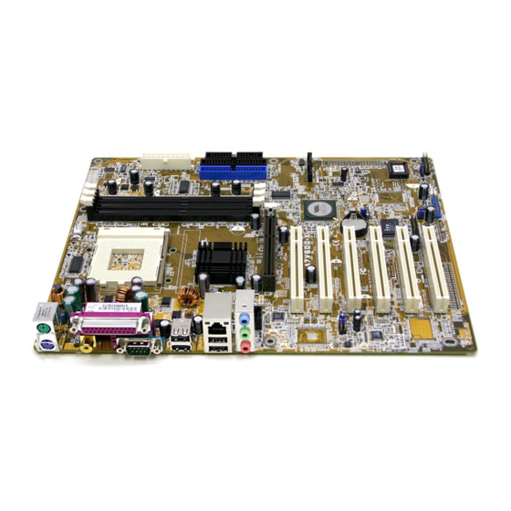
Page 18: Motherboard Overview
1.3.1 Major components The following are the major components of the A7V600-F motherboard as pointed out in the picture on page 1-7. 4-pin ATX power connector 17. - Page 19 ASUS A7V600-F motherboard user guide...
-
Page 20: Core Specifications
3GB system memory using unbuffered non-ECC PC2700/ 2100 DDR DIMMs. (Note: PC3200 maximum to 2 DIMMs support only. Visit the ASUS website (www.asus.com) for the latest qualified DDR400 module list.) IDE connectors. These dual-channel bus master IDE connectors support up to four Ultra DMA133/100/66, PIO Modes 3 &... - Page 21 RJ-45 port. This port allows connection to a Local Area Network (LAN) through a network hub. Line In jack. This Line In (light blue) jack connects a tape player or other audio sources. In 6-channel mode, the function of this jack becomes Rear Speaker Out. ASUS A7V600-F motherboard user guide...
- Page 22 Line Out jack. This Line Out (lime) jack connects a headphone or a speaker. In 6-channel mode, the function of this jack becomes Front Speaker Out. Microphone jack. This Mic (pink) jack connects a microphone. In 6-channel mode, the function of this jack becomes Center Speaker/ Subwoofer.
-
Page 23: Chapter 2: Hardware Information
Chapter 2 This chapter describes the hardware setup procedures that you have to perform when installing system components. It includes details on the switches, jumpers, and connectors on the motherboard. Hardware information... - Page 24 Chapter summary Motherboard installation ....... 2-1 Motherboard layout ........2-2 Before you proceed ........2-3 Central Processing Unit (CPU) ..... 2-4 System memory ..........2-6 Expansion slots ........... 2-10 Jumpers ............2-14 Connectors ........... 2-17 ASUS A7V600-F motherboard...
-
Page 25: Motherboard Installation
Motherboard installation Before you install the motherboard, study the configuration of your chassis to ensure that the motherboard fits into it. The A7V600-F uses the ATX form factor that measures 12 inches x 9.6 inches (30.5 x 24.5 cm). Make sure to unplug the power cord before installing or removing the motherboard. -
Page 26: Motherboard Layout
B: USB3 KT600 Chipset Top:Line In Center:Line Out Below:Mic In PWR_FAN Accelerated Graphics Port (AGP) PCI1 SATA2 SATA1 VT8237 PCI2 South A7V600-F Bridge FP_AUDIO PCI3 CR2032 3V Lithium Cell ® CMOS Power SPDIF _IN ALC655 PCI4 CLRTC Super PCI5 2Mbit... -
Page 27: Before You Proceed
When lit, the green LED (SB_PWR1) indicates that the system is ON, in sleep mode, or in soft-off mode, a reminder that you should shut down the system before removing or plugging in any motherboard component. SB_PWR A7V600-F ® Standby Powered A7V600-F Onboard LED Power ASUS A7V600-F motherboard user guide... -
Page 28: Central Processing Unit (Cpu)
2.4.1 Overview The motherboard provides a Socket A (462) for CPU installation. AMD processors offer gigahertz speeds to support all the latest computing platforms and applications. The A7V600-F supports Athlon XP and Athlon processors with Thoroughbred/Barton core support. CPU NOTCH... -
Page 29: Installing The Cpu
CPU, make sure that exposed CPU capacitors do not touch the heatsink, or damage may occur! Do not neglect to set the correct Bus Frequency and leave the CPU Multiple setting at default to avoid start-up problems. ASUS A7V600-F motherboard user guide... -
Page 30: System Memory
Memory Module (DIMM) sockets. These sockets support up to 3GB system memory using 184-pin unbuffered non-ECC PC2700/2100 DDR DIMMs. (Note: PC3200 maximum to 2 DIMMs support only. Visit the ASUS website (www.asus.com) for the latest qualified DDR400 module list.) A7V600-F ®... -
Page 31: Ddr400 Qualified Vendor List
Make sure to use only the tested and qualified DDR400 DIMMs listed above. Other DDR DIMMs manufactured by other vendors may not be suitable for this motherboard. Visit the ASUS website (www.asus.com) for the latest qualified vendor DDR400 module list. -
Page 32: Installing A Dimm
2.5.3 Installing a DIMM Make sure to unplug the power supply before adding or removing DIMMs or other system components. Failure to do so may cause severe damage to both the motherboard and the components. Follow these steps to install a DIMM. 1. -
Page 33: Removing A Dimm
1. Simultaneously press the retaining clips outward to unlock the DIMM. Support the DIMM lightly with your fingers when pressing the retaining clips. The DIMM might get damaged when it flips out with extra force. 2. Remove the DIMM from the socket. ASUS A7V600-F motherboard user guide... -
Page 34: Expansion Slots
Expansion slots In the future, you may need to install expansion cards. The motherboard has five PCI slots and one Accelerated Graphics Port (AGP) slot. The following sub-sections describe the slots and the expansion cards that they support. Make sure to unplug the power cord before adding or removing expansion cards. -
Page 35: Standard Interrupt Assignments
When using PCI cards on shared slots, ensure that the drivers support “Share IRQ” or that the cards do not need IRQ assignments. Otherwise, conflicts will arise between the two PCI groups, making the system unstable and the card inoperable. ASUS A7V600-F motherboard user guide 2-11... -
Page 36: Pci Slots
+1.5V specification. Note the notches on the card golden fingers to ensure that they fit the AGP slot on your motherboard. Install only 1.5V AGP cards on this motherboard! A7V600-F ® Keyed for 1.5v A7V600-F Accelerated Graphics Port (AGP) 2-12 Chapter 2: Hardware information... -
Page 37: Cnr Slot
Also, the CNR slot does not take up the motherboard space for one PCI slot because it is a shared slot; rather, it provides you more options. A7V600-F ® A7V600-F Communication & Networking Riser Slot ASUS A7V600-F motherboard user guide 2-13... -
Page 38: Jumpers
+5VSB (Default) A7V600-F ® A7V600-F Keyboard Power Setting 2. IEEE 1394 Setting (3-pin 1394_SW) This jumper permits selection of the IEEE 1394 onboard connector for connection of the IEEE 1394 module. The default setting [1-2] enables the onboard IEEE 1394 connector. Disable the connector by changing the jumpers to [2-3]. -
Page 39: Usb Device Wake-Up
2. The total current consumed must NOT exceed the power supply capability (+5VSB) whether under normal condition or in sleep mode. USBPW12 USBPW34 +5VSB (Default) USBPW78 A7V600-F USBPW56 ® A7V600-F USB Device Wake Up +5VSB (Default) ASUS A7V600-F motherboard user guide 2-15... - Page 40 5. Plug the power cord and turn ON the computer. 6. Hold down the <Del> key during the boot process and enter BIOS setup to re-enter data. CLRTC A7V600-F ® Clear CMOS Normal (Default) A7V600-F Clear RTC RAM 2-16 Chapter 2: Hardware information...
-
Page 41: Connectors
(Pin 5 is removed to prevent incorrect insertion when using ribbon cables with pin 5 plug). FLOPPY NOTE: Orient the red markings on the floppy ribbon cable to PIN 1. A7V600-F ® PIN 1 A7V600-F Floppy Disk Drive Connector ASUS A7V600-F motherboard user guide 2-17... - Page 42 (usually zigzag) on the IDE ribbon cable to PIN 1. A7V600-F ® PIN 1 PIN 1 A7V600-F IDE Connectors For UltraDMA133/100/66 IDE devices, use an 80-conductor IDE cable. The UltraDMA/66 cable included in the motherboard package also supports UltraDMA133/100. 2-18 Chapter 2: Hardware information...
- Page 43 FP_AUDIO A7V600-F ® A7V600-F Front Panel Audio Connector 4. CPU, Chassis, and Power Fan Connectors (3-pin CPU_FAN, PWR_FAN, CHA_FAN) The fan connectors support cooling fans of 350mA~740mA (8.88W max.) or a total of 1A~2.22A (26.64W max.) at +12V. Connect the fan cables to the fan connectors on the motherboard, making sure that the black wire of each cable matches the ground pin of the connector.
- Page 44 +5VSB +5.0VDC +12.0VDC A7V600-F ATX Power Connector 6. IEEE 1394 connector (10-1 pin IE1394_1) This connector is for an optional 1394 module. Attach the 10-1 pin 394 cable plug from the module to this connector. You may also connect a 1394-compliant internal hard disk to this connector.
- Page 45 It also allows the sharing of mono_in (such as a phone) and a mono_out (such as a speaker) between the audio and a voice modem card. AUX(White) A7V600-F CD(Black) ® A7V600-F Internal Audio Connectors ASUS A7V600-F motherboard user guide 2-21...
- Page 46 ® A7V600-F SATA Connectors 10. S/PDIF In connector (3 pin S/PDIF_IN) This connector is for an additional S/PDIF audio module that allows digital instead of analog sound input. SPDIF_IN A7V600-F ® A7V600-F Digital Audio Connector 2-22 Chapter 2: Hardware information...
- Page 47 ® HDLED Reset SW A7V600-F Front Panel Audio Connector • System Power LED Lead (2-pin PLED) This 2-pin connector connects to the system power LED. The LED lights up when you turn on the system power, and blinks when the system is in sleep mode.
- Page 48 2-24 Chapter 2: Hardware information...
-
Page 49: Chapter 3: Powering Up
Chapter 3 This chapter describes the power up sequence and gives information on the BIOS beep codes. Powering up... -
Page 50: Powering Off The Computer
Chapter summary Starting up for the first time ......3-1 Powering off the computer ......3-2 ASUS A7V600-F motherboard... -
Page 51: Starting Up For The First Time
30 seconds from the time you turned on the power, the system may have failed a power-on test. Check the jumper settings and connections or call your retailer for assistance. 7. At power on, hold down <Delete> to enter BIOS Setup. Follow the instructions in Chapter 4. ASUS A7V600-F motherboard user guide... -
Page 52: Powering Off The Computer
Powering off the computer Using the OS shut down function If you use Windows 98SE/ME/2000/XP, click the Start button, click Shut Down, then the OK button to shut down the computer. The power supply should turn off after Windows shuts down. Using the dual function power switch While the system is ON, pressing the power switch for less than 4 seconds puts the system to sleep mode or to soft-off mode, depending on the BIOS... -
Page 53: Chapter 4: Bios Setup
Chapter 4 This chapter tells how to change system settings through the BIOS Setup menus. Detailed descriptions of the BIOS parameters are also provided. BIOS setup... - Page 54 Chapter summary Managing and updating your BIOS ....4-1 BIOS Setup program ........4-9 Main Menu ............ 4-12 Advanced Menu ........... 4-19 Power Menu ..........4-30 Boot Menu ............ 4-35 Exit Menu ............4-37 ASUS A7V600-F motherboard...
-
Page 55: Managing And Updating Your Bios
BIOS later. 4.1.1 Using ASUS EZ Flash to update the BIOS The ASUS EZ Flash feature allows you to easily update the BIOS without having to go through the long process of booting from a diskette and using a DOS-based utility. The EZ Flash is built-in the BIOS firmware so it is accessible by simply pressing <Alt>... - Page 56 5. At the prompt, , type in the “Please Enter File Name for NEW BIOS: _” BIOS file name that you downloaded from the ASUS website, then press <Enter>. EZ Flash will automatically access drive A to look for the file name that you typed.
-
Page 57: Using Aflash To Update The Bios
4. In DOS mode, type A:\AFLASH <Enter> to run AFLASH. If the word “unknown” appears after Flash Memory:, the memory chip is either not programmable or is not supported by the ACPI BIOS and therefore, cannot be programmed by the Flash Memory Writer utility. ASUS A7V600-F motherboard user guide... - Page 58 5. Select 1. Save Current BIOS to File from the Main menu and press <Enter>. The Save Current BIOS To File screen appears. 6. Type a filename and the path, for example, A:\XXX-XX.XXX, then press <Enter>. Chapter 4: BIOS Setup...
- Page 59 BIOS revision will solve your problems. Careless updating may result to more problems with the motherboard! 1. Download an updated ASUS BIOS file from the Internet (WWW or FTP) (see ASUS CONTACT INFORMATION on page x for details) and save to the boot floppy disk you created earlier.
- Page 60 If the Flash Memory Writer utility is not able to successfully update a complete BIOS file, the system may not boot. If this happens, call the ASUS service center for support. Chapter 4: BIOS Setup...
-
Page 61: Recovering The Bios With Crashfree Bios 2
Reading file “A7V600-F.rom”. Completed. Start flashing... DO NOT shutdown or reset the system while updating the BIOS! Doing so may cause system boot failure! 4. When the BIOS update process is complete, reboot the system. ASUS A7V600-F motherboard user guide... - Page 62 4. When the BIOS update process is complete, reboot the system. The recovered BIOS may not be the latest BIOS version for this motherboard. Visit ASUS website (www.asus.com) to download the latest BIOS file. Chapter 4: BIOS Setup...
-
Page 63: Bios Setup Program
Because the BIOS software is constantly being updated, the following BIOS setup screens and descriptions are for reference purposes only, and may not exactly match what you see on your screen. ASUS A7V600-F motherboard user guide... -
Page 64: Bios Menu Bar
4.2.1 BIOS menu bar The top of the screen has a menu bar with the following selections: MAIN Use this menu to make changes to the basic system configuration. ADVANCED Use this menu to enable and make changes to the advanced features. -
Page 65: General Help
While moving around through the Setup program, note that explanations appear in the Item Specific Help window located to the right of each menu. This window displays the help text for the currently highlighted field. ASUS A7V600-F motherboard user guide 4-11... -
Page 66: Main Menu
Main Menu When you enter the Setup program, the following screen appears. System Time [XX:XX:XX] Sets the system to the time that you specify (usually the current time). The format is hour, minute, second. Valid values for hour, minute and second are Hour: (00 to 23), Minute: (00 to 59), Second: (00 to 59). - Page 67 Configuration options: [All Errors] [No Error] [All but Keyboard] [All but Disk] [All but Disk/Keyboard] Installed Memory [XXX MB] This field automatically displays the amount of conventional memory detected by the system during the boot process. ASUS A7V600-F motherboard user guide 4-13...
-
Page 68: Primary And Secondary Master/Slave
4.3.1 Primary and Secondary Master/Slave Cylinders [ 1024 ] Head [255] Sector [63] CHS Capacity 8422MB Maximum LBA Capacity 25590MB Multi-Sector Transfers [Maximum] SMART Monitoring [Disabled] Acoustic Management [Disabled] PIO Mode ULTRA DMA Mode [Disabled] Type [Auto] Select [Auto] to automatically detect an IDE hard disk drive. If automatic detection is successful, Setup automatically fills in the correct values for the remaining fields on this sub-menu. - Page 69 After making your selections on this sub-menu, press the <Esc> key to return to the Main menu. When the Main menu appears, the hard disk drive field displays the size for the hard disk drive that you configured. ASUS A7V600-F motherboard user guide 4-15...
- Page 70 Translation Method [LBA] Select the hard disk drive type in this field. When Logical Block Addressing (LBA) is enabled, the 28-bit addressing of the hard drive is used without regard for cylinders, heads, or sectors. Note that LBA Mode is necessary for drives with more than 504MB storage capacity.
- Page 71 IDE devices. Set to [Disabled] to suppress Ultra DMA capability. To make changes to this field, set the Type field to [User Type HDD]. Configuration options: [0] [1] [2] [3] [4] [5] [6] [Disabled] ASUS A7V600-F motherboard user guide 4-17...
-
Page 72: Keyboard Features
4.3.2 Keyboard Features Boot Up NumLock Status [On] This field enables users to activate the Number Lock function upon system boot. Configuration options: [Off] [On] Keyboard Auto-Repeat Rate [12/Sec] This controls the speed at which the system registers repeated keystrokes. Options range from 6 to 30 characters per second. -
Page 73: Advanced Menu
(when CPU Speed is set to [Manual]) This feature tells the clock generator what frequency to send to the system bus and PCI bus. The bus frequency (external frequency) multiplied by the bus multiple equals the CPU speed. ASUS A7V600-F motherboard user guide 4-19... - Page 74 Memory Frequency (Mhz) [Auto] This field allows you to select a higher memory frequency for better system performance. The options that appear in the popup menu vary according to the CPU Frequency (MHz). Configuration options: [Auto] [266] [333] [400] CPU VCore Setting [Auto] The [Manual] setting allows you to manually select the core voltage supplied to the CPU (see next item).
- Page 75 Allows you to select the CD-ROM drive that you wish to use for the Instant Music CD playback. Configuration options depends on the optical drives installed on your system. The above item appears only if you enabled the Instant Music item. ASUS A7V600-F motherboard user guide 4-21...
-
Page 76: Chip Configuration
4.4.1 Chip Configuration SDRAM Configuration [By SPD] This parameter allows you to set the optimal timings for items 2–5, depending on the memory modules that you are using. The default setting is [By SPD], which configures items 2–5 by reading the contents in the SPD (Serial Presence Detect) device. - Page 77 266MB/s even if you are using an AGP 8X card. Configuration options: [Auto] [1X Mode] [2X Mode] [4X Mode] [8X Mode] AGP performance control [Disabled] Configuration options: [Disabled] [Enabled] AGP Fast Write control [Disabled] Configuration options: [Disabled] [Enabled] ASUS A7V600-F motherboard user guide 4-23...
- Page 78 Video Memory Cache Mode [UC] USWC (uncacheable, speculative write combining) is a new cache technology for the video memory of the processor. It can greatly improve the display speed by caching the display data. You must set this to UC (uncacheable) if your display card does not support this feature, otherwise the system may not boot.
-
Page 79: I/O Device Configuration
The default setting [R/W] allows both reads and writes. Configuration options: [R/W] [Read Only] Onboard Serial Port 1 [3F8H/IRQ4] This field allows you to set the address for the onboard serial connector. Configuration options: [3F8H/IRQ4] [2F8H/IRQ3] [3E8H/IRQ4] [2E8H/ IRQ10] [Disabled] ASUS A7V600-F motherboard user guide 4-25... - Page 80 Onboard Parallel Port [378H/IRQ7] This field allows you to set the address of the onboard parallel port connector. If you disable this field, the Parallel Port Mode and ECP DMA Select configurations are not available. Configuration options: [Disabled] [378H/IRQ7] [278H/IRQ5] Parallel Port Mode [ECP+EPP] This field allows you to set the operation mode of the parallel port.
- Page 81 These fields allow you to disable or set to auto detect the onboard AC97 modem controller.Configuration options: [Auto] [Disabled] Onboard AC97 Audio Controller [Auto] These fields allow you to disable or set to auto detect the onboard AC97 audio controller.Configuration options: [Auto] [Disabled] ASUS A7V600-F motherboard user guide 4-27...
-
Page 82: Pci Configuration
4.4.3 PCI Configuration Slot 1/5, Slot 2/6, Slot 3, Slot 4 IRQ [Auto] These fields automatically assign the IRQ for each PCI slot. The default setting for each field is [Auto], which utilizes auto-routing to determine IRQ assignments. Configuration options: [Auto] [NA] [3] [4] [5] [7] [9] [10] [11] [12] [14] [15] PCI/VGA Palette Snoop [Disabled] Some non-standard VGA cards, like graphics accelerators or MPEG video... -
Page 83: Pci Irq Resource Exclusion
IRQ is NOT required by a legacy ISA card. Set the IRQ field to [Yes] if you install a legacy ISA card that requires a unique IRQ and you are NOT using ICU. Configuration options: [No/ICU] [Yes] ASUS A7V600-F motherboard user guide 4-29... -
Page 84: Power Menu
Power Menu The Power menu allows you to reduce power consumption. This feature turns off the video display and shuts down the hard disk after a period of inactivity. Power Management [User Defined] This field allows you to activate or deactivate the automatic power saving features. - Page 85 4 seconds puts the system in sleep mode. Regardless of the setting, holding the ATX switch for more than 4 seconds powers off the system. Configuration options: [Soft off] [Suspend] ASUS A7V600-F motherboard user guide 4-31...
-
Page 86: Power Up Control
4.5.1 Power Up Control AC PWR Loss Restart [Enabled] This allows you to set whether or not to reboot the system after power interruptions. [Disabled] leaves your system off while [Enabled] reboots the system. [Previous State] sets the system back to the state it was before the power interruption. - Page 87 This allows an unattended or automatic system power up. You may configure your system to power up at a certain time of the day by selecting [Everyday] or at a certain time and day by selecting [By Date]. Configuration options: [Disabled] [Everyday] [By Date] ASUS A7V600-F motherboard user guide 4-33...
-
Page 88: Hardware Monitor
4.5.2 Hardware Monitor MB Temperature [xxxC/xxxF] CPU Temperature [xxxC/xxxF] The onboard hardware monitor automatically detects and displays the motherboard and CPU temperatures. CPU Fan Speed [xxxxRPM] or [N/A] Power Fan Speed [xxxxRPM] or [N/A] Chassis Fan Speed [xxxxRPM] or [N/A] The onboard hardware monitor automatically detects and displays the CPU, power, and chassis fan speeds in rotations per minute (RPM). -
Page 89: Boot Menu
This field allows you to select which ATAPI CD-ROM drive to use in the boot sequence. Pressing [Enter] will show the product IDs of all your connected ATAPI CD-ROM drives. Other Boot Device Select [INT18 Device (Network)] Configuration options: [Disabled] [SCSI Boot Device] [INT18 Device (Network)] ASUS A7V600-F motherboard user guide 4-35... - Page 90 This allows you to enable or disable the full screen logo display feature. Configuration options: [Disabled] [Enabled] Make sure that the above item is set to [Enabled] if you wish to use the ASUS MyLogo™ feature. Interrupt Mode [APIC] The Advanced Programmable Interrupt Controller (APIC) setting allows you to distribute interrupt routings other than the 16 IRQs.
-
Page 91: Exit Menu
Select this option only if you do not want to save the changes that you made to the Setup program. If you made changes to fields other than system date, system time, and password, the BIOS asks for a confirmation before exiting. ASUS A7V600-F motherboard user guide 4-37... -
Page 92: Discard Changes
Load Setup Defaults This option allows you to load the default values for each of the parameters on the Setup menus. When you select this option or if you press <F5>, a confirmation window appears. Select [Yes] to load default values.