Asus A7V400-MX SE User Manual
Asus computer hardware user manual
Hide thumbs
Also See for A7V400-MX SE:
- User manual (64 pages) ,
- Guía de inicio rápido (21 pages) ,
- User manual (64 pages)
Table of Contents
Advertisement
Quick Links
Advertisement
Table of Contents

Related Manuals for Asus A7V400-MX SE


Summary of Contents for Asus A7V400-MX SE
- Page 2 INCIDENTAL, OR CONSEQUENTIAL DAMAGES (INCLUDING DAMAGES FOR LOSS OF PROFITS, LOSS OF BUSINESS, LOSS OF USE OR DATA, INTERRUPTION OF BUSINESS AND THE LIKE), EVEN IF ASUS HAS BEEN ADVISED OF THE POSSIBILITY OF SUCH DAMAGES ARISING FROM ANY DEFECT OR ERROR IN THIS MANUAL OR PRODUCT.
-
Page 3: Table Of Contents
Notices ... v Safety information ... vi About this guide ... vii A7V400-MX SE specifications summary ... viii Chapter 1: Chapter 1: Product introduction Product introduction Chapter 1: Chapter 1: Chapter 1: Product introduction Product introduction Product introduction Welcome! ... 1-2 Package contents ... - Page 4 Managing and updating your BIOS ... 2-2 2.1.1 Creating a bootable floppy disk ... 2-2 2.1.2 AwardBIOS Flash Utility ... 2-3 2.1.3 ASUS CrashFree BIOS utility ... 2-4 2.1.4 ASUS EZ Flash utility ... 2-4 2.1.5 ASUS Update utility ... 2-5 BIOS beep codes ... 2-7 BIOS setup program ...
- Page 5 Federal Communications Commission Statement Federal Communications Commission Statement Federal Communications Commission Statement Federal Communications Commission Statement Federal Communications Commission Statement This device complies with FCC Rules Part 15. Operation is subject to the following two conditions: • This device may not cause harmful interference, and •...
- Page 6 Electrical safety Electrical safety Electrical safety Electrical safety Electrical safety • To prevent electrical shock hazard, disconnect the power cable from the electrical outlet before relocating the system. • When adding or removing devices to or from the system, ensure that the power cables for the devices are unplugged before the signal cables are connected.
- Page 7 A S U S w e b s i t e s A S U S w e b s i t e s The ASUS websites worldwide provide updated information on ASUS hardware and software products. Refer to the ASUS contact information.
- Page 8 C P U C P U C P U C P U C P U C h i p s e t C h i p s e t C h i p s e t C h i p s e t C h i p s e t Front Side Bus (FSB) Front Side Bus (FSB)
- Page 9 B I O S f e a t u r e s B I O S f e a t u r e s WfM2.0, SM BIOS 2.3,ASUS EZ Flash, ASUS CrashFree BIOS, ASUS C.O.P. (CPU Overheating Protection) I n d u s t r y s t a n d a r d...
- Page 10 x x x x x...
- Page 11 This chapter describes the motherboard features and the new technologies it supports.
-
Page 12: Product Highlights
T h a n k y o u f o r b u y i n g a n A S U S The motherboard delivers a host of new features and latest technologies, making it another standout in the long line of ASUS quality motherboards! Before you start installing the motherboard, and hardware devices on it, check the items in your package with the list below. - Page 13 DDR memory support DDR memory support DDR memory support DDR memory support DDR memory support Employing the Double Data Rate (DDR) memory technology, the motherboard supports up to 2 GB of system memory using DDR 333/266/ 200 DIMMs. The fast 333 MHz memory bus delivers the required bandwidth for the latest 3D graphics, multimedia, and Internet applications.
-
Page 14: Innovative Asus Features
ASUS EZ Flash BIOS ASUS EZ Flash BIOS With the ASUS EZ Flash, you can easily update the system BIOS even before loading the operating system. No need to use a DOS-based utility or boot from a floppy disk. See page 2-4 for details. - Page 15 LED. A7V400-MX SE A7V400-MX SE Onboard LED A S U S A 7 V 4 0 0 - M X S E A S U S A 7 V 4 0 0 - M X S E...
-
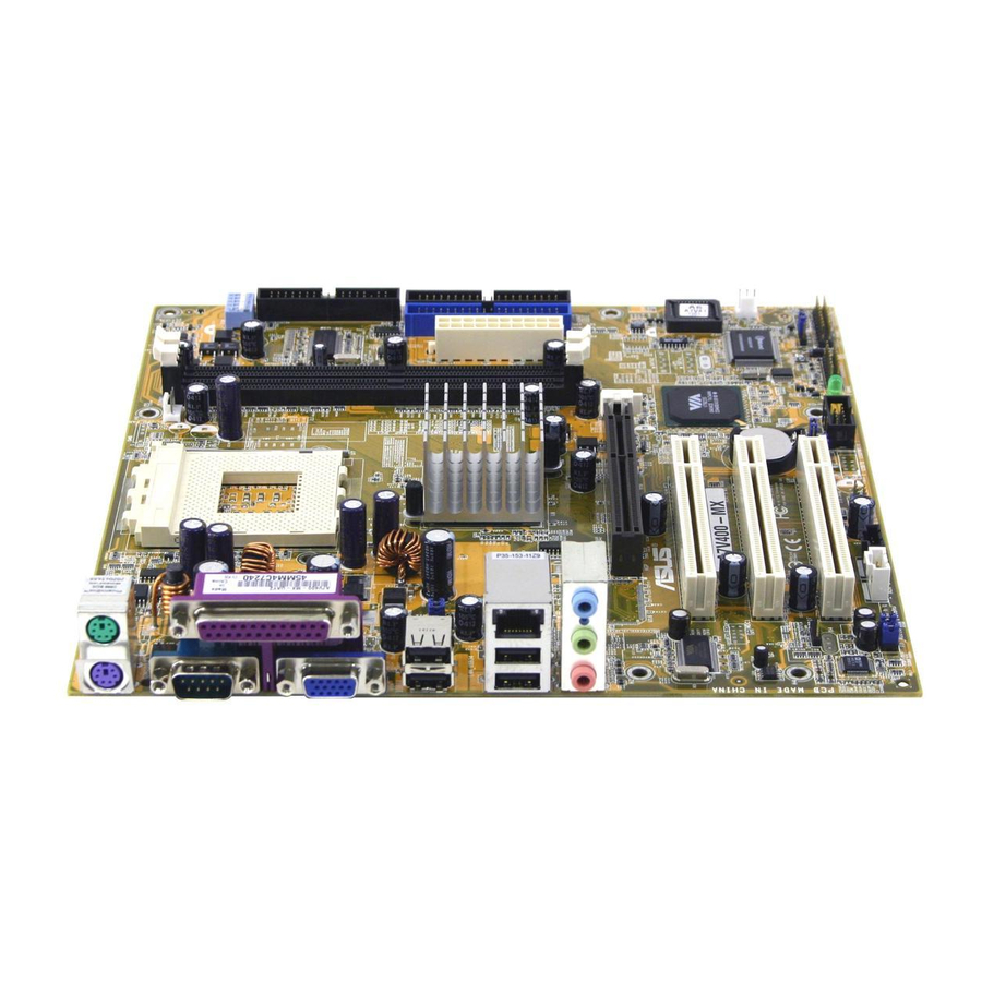
Page 16: Motherboard Layout
1 - 6 1 - 6 1 - 6 1 - 6 1 - 6 24.5cm (9.6in) Socket 462 CPU_FAN KM400A Accelerated Graphics Port (AGP1) PCI1 A7V400-MX SE PCI2 CR2032 3V Lithium Cell CMOS Power PCI3 CLRTC USBPWR56 USBPWR78 USB56 USB78... -
Page 17: Placement Direction
1.5.2 1.5.2 1.5.2 Placement direction Placement direction Placement direction 1.5.2 1.5.2 Placement direction Placement direction When installing the motherboard, make sure that you place it into the chassis in the correct orientation. The edge with external ports goes to the rear part of the chassis as indicated in the image below. -
Page 18: Overview
CPU. A fan and heatsink should be installed on top of the CPU to prevent overheating. This motherboard does not support AMD processors with less than 1 GHz core speed. A7V400-MX SE A7V400-MX SE Socket 462 1.6.2 1.6.2 Installing the CPU Installing the CPU 1.6.2... -
Page 19: Memory Configurations
SDRAM DIMMs. Each DIMM socket is double-sided. A7V400-MX SE A7V400-MX SE 184-pin DDR DIMM sockets * You can install a DDR400 DIMM(s) on the slot(s). However, a DDR400 DIMM may only run at speeds of up to 333 MHz (DDR333). - Page 20 DDR400 Qualified Vendors List DDR400 Qualified Vendors List DDR400 Qualified Vendors List DDR400 Qualified Vendors List DDR400 Qualified Vendors List S i z e S i z e V e n d o r V e n d o r S i z e S i z e S i z e V e n d o r...
- Page 21 S i d e ( s ) C L - CAS Latency Visit the ASUS website for the latest DDR400 Qualified Vendors List. A S U S A 7 V 4 0 0 - M X S E A S U S A 7 V 4 0 0 - M X S E...
- Page 22 S i d e ( s ) S S - Single-sided D S C L - CAS Latency Visit the ASUS website for the latest DDR333 Qualified Vendors List. 1 - 1 2 1 - 1 2 1 - 1 2...
-
Page 23: Installing A Dimm
1.7.3 1.7.3 1.7.3 Installing a DIMM Installing a DIMM Installing a DIMM 1.7.3 1.7.3 Installing a DIMM Installing a DIMM Make sure to unplug the power supply before adding or removing DIMMs or other system components. Failure to do so may cause severe damage to both the motherboard and the components. -
Page 24: Installing An Expansion Card
In the future, you may need to install expansion cards. The following sub-sections describe the slots and the expansion cards that they support. Make sure to unplug the power cord before adding or removing expansion cards. Failure to do so may cause you physical injury and damage motherboard components. - Page 25 Standard interrupt assignments Standard interrupt assignments Standard interrupt assignments Standard interrupt assignments Standard interrupt assignments I R Q I R Q I R Q I R Q I R Q P r i o r i t y P r i o r i t y P r i o r i t y P r i o r i t y P r i o r i t y...
-
Page 26: Agp Slot
The motherboard has an Accelerated Graphics Port (AGP) slot that supports +1.5 V 8X/4X AGP graphics card. Note the notches on the card golden fingers to ensure that they fit into the AGP slot. A7V400-MX SE A7V400-MX SE Accelerated Graphics Port (AGP) 1.8.4 1.8.4 1.8.4... - Page 27 ON and OFF positions of the switches. A7V400-MX SE A7V400-MX SE DIP switches The option to set the CPU core bus frequency multiple is available only on unlocked CPUs. If you are using a locked CPU, setting the switches does not produce any effect.
-
Page 28: Clear Rtc Ram
Except when clearing the RTC RAM, never remove the cap on CLRTC jumper default position. Removing the cap will cause system boot failure! A7V400-MX SE A7V400-MX SE Clear RTC RAM 1 - 1 8 1 - 1 8 1 - 1 8... - Page 29 S3 and S4 sleep modes (no power to CPU, DRAM in slow refresh, power supply in reduced power mode). A7V400-MX SE A7V400-MX SE USB device wake up • The USB device wake-up feature requires a power supply that can provide 500mA on the +5VSB lead for each USB port;...
-
Page 30: Connectors
1.10.1 1.10.1 Rear panel connectors Rear panel connectors 1.10.1 1.10.1 Rear panel connectors 1.10.1 Rear panel connectors Rear panel connectors 1 . 1 . P S / 2 m o u s e p o r t ( g r e e n ) . This port is for a PS/2 mouse. P S / 2 m o u s e p o r t ( g r e e n ) . -
Page 31: Internal Connectors
FDD cable with a covered Pin 5. A7V400-MX SE A7V400-MX SE Floppy disk drive connector 2 . 2 . I D E c o n n e c t o r s ( 4 0 - 1 p i n P R I _ I D E , S E C _ I D E ) - Page 32 A7V400-MX SE A7V400-MX SE SATA connector I m p o r t a n t n o t e s o n S e r i a l A T A I m p o r t a n t n o t e s o n S e r i a l A T A...
- Page 33 The USB module is purchased separately. A7V400-MX SE A7V400-MX SE USB connectors Never connect a 1 3 9 4 c a b l e damage the motherboard! 6 . 6 .
- Page 34 This connector is for the front panel audio daughterboard cable. This connector supports the front panel audio I/O ports. A7V400-MX SE A7V400-MX SE Front panel audio connector By default, the pins labeled LINE_OUT_R/BLINE_OUT_R and the pins LINE_OUT_L/BLINE_OUT_L are shorted with jumper caps. Remove the caps only when you are connecting the front panel audio cable.
- Page 35 The S/PDIF module is purchased separately. A7V400-MX SE A7V400-MX SE Digital audio connector 1 0 . 1 0 . A T X p o w e r c o n n e c t o r ( 2 0 - p i n A T X P W R ) A T X p o w e r c o n n e c t o r ( 2 0 - p i n A T X P W R ) 1 0 .
-
Page 36: Sleep Mode
This connector supports several chassis-mounted functions. A7V400-MX SE A7V400-MX SE System panel connector S y s t e m p o w e r L E D ( 3 - p i n P L E D ) S y s t e m p o w e r L E D ( 3 - p i n P L E D ) •... - Page 37 This chapter tells how to change the system settings through the BIOS Setup menus. Detailed descriptions of the BIOS parameters are also provided.
-
Page 38: Chapter 2: Bios Setup
ASUS EZ Flash ASUS EZ Flash ASUS EZ Flash ASUS EZ Flash (Updates the BIOS in DOS mode using a floppy disk.) ASUS EZ Flash A S U S U p d a t e A S U S U p d a t e... -
Page 39: Awardbios Flash Utility
AwardBIOS Flash utility (AWDFLASH.EXE). To update the BIOS using the AwardBIOS Flash Utility: Download the latest BIOS file from the ASUS website. Rename the file to *.BIN, then save it to the bootable floppy disk you created earlier. -
Page 40: Asus Crashfree Bios Utility
ASUS CrashFree BIOS utility ASUS CrashFree BIOS utility The ASUS CrashFree BIOS allows you to update the BIOS file when it fails or gets corrupted. You can update a corrupted BIOS file using a floppy disk that contains the updated BIOS file and the AWDFLASH utility. -
Page 41: Asus Update Utility
2.1.5 2.1.5 ASUS Update utility ASUS Update utility The ASUS Update is a utility that allows you to manage, save, and update the motherboard BIOS in Windows allows you to: • Save the current BIOS file • Download the latest BIOS file from the Internet •... - Page 42 A S U S U p d a t e A S U S U p d a t e. The ASUS Update main window appears. Select U p d a t e B I O S f r o m a...
-
Page 43: Bios Beep Codes
When you turn the power on and the system runs POST (Power On Self Tests), you will hear BIOS beeps. Refer to the following table for the meaning of the beeps. Award BIOS beep codes Award BIOS beep codes Award BIOS beep codes Award BIOS beep codes Award BIOS beep codes B e e p... -
Page 44: Bios Menu Bar
The BIOS setup screens shown in this section are for reference purposes only, and may not exactly match what you see on your screen. • Visit the ASUS website (www.asus.com) to download the latest BIOS file for this motherboard. 2.3.1 2.3.1... - Page 45 General help General help General help General help General help In addition to the Item Help window, the BIOS setup program also provides a General Help screen. You may launch this screen from any menu by simply pressing <F1>. The General Help screen lists the legend keys and their corresponding functions.
- Page 46 2 - 1 0 2 - 1 0 2 - 1 0 2 - 1 0 15 : 30 : 30 Wed, Jan 05 2003 [1.44M, 3.5 in.] [ST321122A] [ASUS CDS520/A] [None] [None] [None] [None] 256MB : Select Item : Change Value...
- Page 47 Primary/Secondary IDE Master/Slave Primary/Secondary IDE Master/Slave Primary/Secondary IDE Master/Slave Primary/Secondary IDE Master/Slave Primary/Secondary IDE Master/Slave Primary IDE Master Primary IDE Master Access Mode Capacity Cylinder Head Sector PIO Mode UDMA Mode Transfer Mode F1 : Help : Select Item ESC : Exit : Select Menu Primary IDE Master/Slave [Auto] Primary IDE Master/Slave [Auto]...
- Page 48 [Manual] and [CHS] Settings [Manual] and [CHS] Settings [Manual] and [CHS] Settings [Manual] and [CHS] Settings [Manual] and [CHS] Settings Primary IDE Master Access Mode Capacity Cylinder Head Sector PIO Mode UDMA Mode Transfer Mode : Help ESC : Exit Manually enter the number of cylinders, heads and sectors per track for the drive.
- Page 49 H e a d H e a d H e a d H e a d H e a d Configures the number of read/write heads. Refer to the drive documentation to determine the correct value. To make changes to this field, set the IDE Primary Master field to [Manual] and the Access Mode to [CHS].
- Page 50 Capacity Capacity Capacity Capacity Capacity Refer to the previous section. Cylinder Cylinder Cylinder Cylinder Cylinder Refer to the previous section. H e a d H e a d H e a d H e a d H e a d Refer to the previous section.
-
Page 51: Advanced Menu
The Advanced menu items allow you to change the settings for the CPU and other system devices. CPU Configuration Memory Configuration Chipset PCIPnP Onboard Devices Configuration USB Configuration F1 : Help : Select Item ESC : Exit : Select Menu 2.5.1 2.5.1 2.5.1... -
Page 52: Memory Configuration
2.5.2 2.5.2 2.5.2 Memory Configuration Memory Configuration Memory Configuration 2.5.2 2.5.2 Memory Configuration Memory Configuration This menu allows you to change the system memory settings. Current DRAM Frequency DRAM Clock DRAM Timing DRAM CAS Latency Bank Interleave Pre-charge to Active (Trp) Active to Precharge (Tras) Active to CMD (Trcd) DRAM Burst Length... -
Page 53: Chipset
Active to Precharge (Tras) [7T] Active to Precharge (Tras) [7T] Active to Precharge (Tras) [7T] Active to Precharge (Tras) [7T] Active to Precharge (Tras) [7T] Configuration options: [6T] [7T] [8T] [9T] Active to CMD (Trcd) [5T] Active to CMD (Trcd) [5T] Active to CMD (Trcd) [5T] Active to CMD (Trcd) [5T] Active to CMD (Trcd) [5T]... - Page 54 AGP Bridge Configuration AGP Bridge Configuration AGP Bridge Configuration AGP Bridge Configuration AGP Bridge Configuration AGP Bridge Configuration Graphics Aperture Size AGP Mode AGP Driving Control AGP Driving Value AGP Fast Write Onboard Video Memory : Help : Select Item ESC : Exit : Select Menu Graphics Aperture Size [64MB]...
-
Page 55: Pcipnp
2.5.4 2.5.4 2.5.4 PCIPnP PCIPnP PCIPnP 2.5.4 2.5.4 PCIPnP PCIPnP The PCIPnP menu allows you to change the settings for installed PCI devices. Select an item then press <Enter> to display the sub-menu. Plug and Play OS Resources Controlled By IRQ Resources PCI/VGA Palette Snoop : Help... -
Page 56: Onboard Devices Configuration
IRQ 3, 4, 5, 7, 9, 10, 11, 12, 14, 15 assigned to IRQ 3, 4, 5, 7, 9, 10, 11, 12, 14, 15 assigned to IRQ 3, 4, 5, 7, 9, 10, 11, 12, 14, 15 assigned to IRQ 3, 4, 5, 7, 9, 10, 11, 12, 14, 15 assigned to IRQ 3, 4, 5, 7, 9, 10, 11, 12, 14, 15 assigned to The IRQ Resources sub-menu is activated when the R e s o u r c e s C o n t r o l l e d b y... - Page 57 Onboard LAN Boot ROM [Disabled] Onboard LAN Boot ROM [Disabled] Onboard LAN Boot ROM [Disabled] Onboard LAN Boot ROM [Disabled] Onboard LAN Boot ROM [Disabled] Allows you to turn on or off the onboard LAN boot ROM. This item appears only when onboard LAN is enabled.
-
Page 58: Usb Configuration
2.5.6 2.5.6 2.5.6 USB Configuration USB Configuration USB Configuration 2.5.6 2.5.6 USB Configuration USB Configuration The USB Configuration menu allows you to adjust the settings for the onboard USB controllers. Select an item then press <Enter> to display the sub-menu. OnChip USB Controller OnChip EHCI Controller USB Legacy Support... -
Page 59: Power Menu
The Power menu items allow you to change the settings for the Advanced Power Management (APM). Select an item, then press <Enter> to display the configuration options. ACPI Suspend Type ACPI APIC Support APM Configuration Hardware Monitor F1 : Help : Select Item ESC : Exit : Select Menu... -
Page 60: Apm Configuration
2.6.1 2.6.1 2.6.1 APM Configuration APM Configuration APM Configuration 2.6.1 2.6.1 APM Configuration APM Configuration PS2KB Wakeup Select PS2KB Wakeup Password PS2KB Wakeup from S3/S4/S5 PS2MS Wakeup from S3/S4/S5 USB Resume from S3/S4 Power On By PCI Devices Modem Ring Resume Power On By RTC Alarm Date (of Month) Resume Time (hh:mm:ss) - Page 61 PS2MS Wakeup from S3/S4/S5 [Disabled] PS2MS Wakeup from S3/S4/S5 [Disabled] PS2MS Wakeup from S3/S4/S5 [Disabled] PS2MS Wakeup from S3/S4/S5 [Disabled] PS2MS Wakeup from S3/S4/S5 [Disabled] When set to [Enabled], this parameter allows you to use the PS/2 mouse to turn on the system. This requires an ATX power supply that provides at least 1A on the +5VSB lead.
-
Page 62: Hardware Monitor
2.6.2 2.6.2 2.6.2 Hardware Monitor Hardware Monitor Hardware Monitor 2.6.2 2.6.2 Hardware Monitor Hardware Monitor Shutdown Temperature System Temperature CPU Temperature Chassis Fan Speed CPU Fan Speed Vcore + 3.3 V + 5 V +12 V : Help ESC : Exit Shutdown Temperature [Disabled] Shutdown Temperature [Disabled] Shutdown Temperature [Disabled]... -
Page 63: Boot Menu
The Boot menu items allow you to change the system boot settings. Select a sub-menu, then press <Enter> to display the configuration options. Boot Device Priority Removable Drives Hard Disk Drives CDROM Drives Boot Settings Configuration Security F1 : Help : Select Item ESC : Exit : Select Menu... -
Page 64: Removable Drives
2.7.2 2.7.2 2.7.2 Removable Drives Removable Drives Removable Drives 2.7.2 2.7.2 Removable Drives Removable Drives This menu allows you to arrange the removable drive sequence. The screen shows the removable drive(s) installed in the system. When more than one removable drives are detected, use the arrow up or down keys to arrange the devices according to your boot priority. -
Page 65: Cdrom Drives
When more than one optical drives are detected, use the arrow up or down keys to arrange the devices according to your boot priority. CDROM Drives 1. 1st Slave : ASUS CD-S520/A :Move PU/PD/+/-:Change Priority ESC : Exit : Select Menu 2.7.5... -
Page 66: Security
Bootup Num-lock [On] Bootup Num-lock [On] Bootup Num-lock [On] Bootup Num-lock [On] Bootup Num-lock [On] Allows you to select the power-on state for the keyboard NumLock key. Configuration options: [Off] [On] Halt On [All Errors] Halt On [All Errors] Halt On [All Errors] Halt On [All Errors] Halt On [All Errors] Sets the system to halt on errors according to the system functions... - Page 67 To clear the password: Select either the S u p e r v i s o r P a s s w o r d S u p e r v i s o r P a s s w o r d S u p e r v i s o r P a s s w o r d or U s e r P a s s w o r d S u p e r v i s o r P a s s w o r d S u p e r v i s o r P a s s w o r d...
-
Page 68: Exit Menu
The Exit menu items allow you to save or discard your changes to, and/or load the optimal or failsafe default values for the BIOS items. Exit & Save Changes Exit & Discard Changes Load Setup Default Discard Changes F1 : Help ESC : Exit Pressing <Esc>... - Page 69 This chapter describes the contents of the support CD that comes with the motherboard package.
-
Page 70: Chapter 3: Software Support
The contents of the support CD are subject to change at any time without notice. Visit the ASUS website(www.asus.com) for updates. 3.2.1 3.2.1 Running the support CD Running the support CD 3.2.1... -
Page 71: Drivers Menu
Utilities menu Utilities menu Utilities menu The Utilities menu shows the applications and other software that the motherboard supports. ASUS PC Probe ASUS PC Probe ASUS PC Probe ASUS PC Probe ASUS PC Probe This smart utility monitors the fan speed, CPU temperature, and system voltages, and alerts you of any detected problems. -
Page 72: Contacts Menu
C o n t a c t C o n t a c t C o n t a c t tab to display the ASUS contact information. You can C o n t a c t also find this information on the inside front cover of this user guide.