Table of Contents
Advertisement
Advertisement
Table of Contents

Related Manuals for Asus A7V600-X


Summary of Contents for Asus A7V600-X
- Page 1 A7V600-X User Guide...
- Page 2 Product warranty or service will not be extended if: (1) the product is repaired, modified or altered, unless such repair, modification of alteration is authorized in writing by ASUS; or (2) the serial number of the product is defaced or missing.
-
Page 3: Table Of Contents
IRQ assignments for this motherboard ....... 1.10.3 AGP slot ............. 1-15 1.11 Jumpers ................1-16 1.12 Connectors ............... 1-18 Chapter 2: BIOS information 2.1 Managing and updating your BIOS ........2-2 2.1.1 Using ASUS EZ Flash to update the BIOS .... 2-2... - Page 4 Utilities menu ............3-3 3.2.4 ASUS Contact Information ........3-4 3.3 ASUS Instant Music Lite ............. 3-5 3.4 RAID 0 / RAID 1 / RAID 0 + 1 Configurations ....3-7 3.4.1 Install the Serial ATA (SATA) hard disks ....3-8 ®...
-
Page 5: Notices
Notices Federal Communications Commission Statement This device complies with Part 15 of the FCC Rules. Operation is subject to the following two conditions: • This device may not cause harmful interference, and • This device must accept any interference received including interference that may cause undesired operation. -
Page 6: Safety Information
Safety information Electrical safety • To prevent electrical shock hazard, disconnect the power cable from the electrical outlet before relocating the system. • When adding or removing devices to or from the system, ensure that the power cables for the devices are unplugged before the signal cables are connected. -
Page 7: About This Guide
1. ASUS Websites The ASUS websites worldwide provide updated information on ASUS hardware and software products. The ASUS websites are listed in the ASUS Contact Information on page viii. 2. Optional Documentation Your product package may include optional documentation, such as warranty flyers, that may have been added by your dealer. -
Page 8: Asus Contact Information
Web site usa.asus.com Technical Support Telephone (General) +1-502-995-0883 (Notebook) +1-510-739-3777 Support fax +1-502-933-8713 Support e-mail tsd@asus.com ASUS COMPUTER GmbH (Germany and Austria) Address Harkort Str. 25, D-40880 Ratingen, Germany Telephone +49-2102-95990 +49-2102-959911 Online contact www.asuscom.de/sales Technical Support Telephone +49-2102-95990 +49-2102-959911 Online support www.asuscom.de/support... -
Page 9: A7V600-X Specifications Summary
ADI AD1888 6-channel CODEC S/PDIF out interface Integrated 10/100 Mbps LAN controller Special Features ASUS EZ Flash Power Loss Restart ASUS C.O.P. (CPU Overheating Protection) ASUS CrashFree BIOS 2 ASUS Instant Music Lite Overclocking ASUS JumperFree Features ASUS C.P.R. (CPU Parameter Recall) - Page 10 A7V600-X specifications summary BIOS features 2Mb Flash ROM, ASUS Jumperfree, Award BIOS, PnP, DMI2.0, WfM2.0, SM BIOS2.3, ASUS EZ Flash, ASUS CrashFree BIOS 2, ASUS C.P.R. Industry standard PCI 2.2, USB 2.0 Manageability WfM 2.0. DMI 2.0, WOR, WOL, chassis intrusion Form Factor ATX form factor: 12 in x 9.6 in (30.5 cm x 24.5 cm)
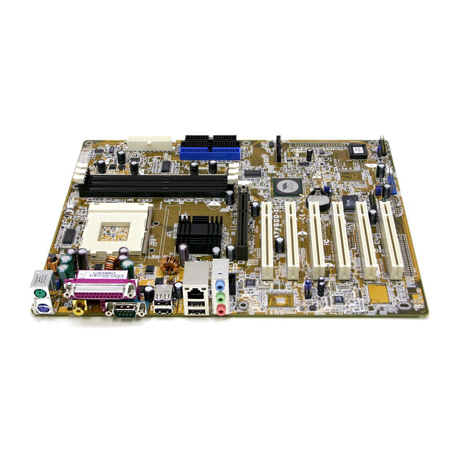
- Page 11 Chapter 1 This chapter gives information about the ASUS A7V600-X motherboard that came with the system.This chapter includes the motherboard layout, jumper settings, and connector locations. ASUS A7V600-X motherboard...
-
Page 12: Welcome
The ASUS A7V600-X motherboard is loaded with the most advanced technologies to deliver the maximum performance for socket A processors. Based on the advanced VIA KT600 chipset with FSB 400 and DDR 400 support, the ASUS A7V600-X also features AGP 8X, Serial ATA, USB 2.0 as well as 6-channel audio, Fast Ethernet LAN and S/PDIF out features. -
Page 13: Special Features
DDR400 (PC3200), the latest and fastest DDR memory standard, supports bandwidth up to 3.2 GB/s to provide enhanced system performance. (Note: PC3200 maximum to 2 DIMMs only. Visit the ASUS website for the latest qualified DDR400 module list.) AGP 8X support AGP 8X (AGP 3.0) is the next generation VGA interface specification that enables... -
Page 14: Crashfree Bios 2
The CrashFree BIOS 2 feature allows you to restore the original BIOS data from the ASUS support CD in case when the BIOS codes and data are corrupted. This protection feature eliminates the need to buy a replacement ROM chip. -
Page 15: Value-Added Solutions
CMOS for more protection. ASUS update This utility allows you to update the motherboard BIOS through a user-friendly interface. Connect to the Internet then to the ASUS FTP site nearest you to obtain the latest BIOS version for your motherboard. ASUS A7V600-X motherboard... -
Page 16: Motherboard Components
Motherboard components Before you install the motherboard, learn about its major components and available features to facilitate the installation and future upgrades. Refer to the succeeding pages for the component descriptions. Chapter 1: Motherboard Information... -
Page 17: Core Specifications
DDR DIMM sockets. These three 184-pin DIMM sockets support up to 3GB system memory using unbuffered non-ECC PC2700/2100 DDR DIMMs. (Note: PC3200 maximum to 2 DIMMs support only. Visit the ASUS website (www.asus.com) for the latest qualified DDR400 module list.) IDE connectors. - Page 18 PCI slots. These six 32-bit PCI 2.2 expansion slots support bus master PCI cards like SCSI or LAN cards with 133MB/s maximum throughput. Audio CODEC . The ADI 1888 is an AC’97 compliant audio CODEC for PC multimedia systems. LAN controller. The Realtek 8201BL Fast Ethernet LAN controller delivers transfer rates of up to 10/100Mbps Ethernet connections.
-
Page 19: Motherboard Layout
PCI1 A7V600-X SATA2 SATA1 VT8237 PCI2 South FP_AUDIO Bridge PCI3 CR2032 3V Lithium Cell CMOS Power AD1980 CODEC PCI4 CLRTC Super PCI5 4Mbit ® Low Pin GAME Count USBPW78 PCI6 SB_PWR USBPW56 CHASSIS CHA_FAN USB56 USB78 PANEL ASUS A7V600-X Motherboard... -
Page 20: Before You Proceed
Before you proceed Take note of the following precautions before you install motherboard components or change any motherboard settings. 1. Unplug the power cord from the wall socket before touching any component. 2. Use a grounded wrist strap or touch a safely grounded object or to a metal object, such as the power supply case, before handling components to avoid damaging them due to static electricity. -
Page 21: Motherboard Installation
Place nine (9) screws into the holes indicated by circles to secure the motherboard to the chassis. Do not overtighten the screws! Doing so may damage the motherboard. Place this side towards the rear of the chassis ASUS A7V600-X Motherboard 1-11... -
Page 22: Central Processing Unit (Cpu)
Central Processing Unit (CPU) The motherboard provides a Socket A (462) for CPU installation. AMD processors offer gigahertz speeds to support all the latest computing platforms and applications. The A7V600-X supports Athlon XP, AMD Athlon , AMD Barton™ and AMD Duron processors. -
Page 23: System Memory
512MB MT16VDDT6464AG-40BC4 MT46V32M8TG-5BC NANYA 512MB NT512D64S8HB1G-5T NT5DS32M8BT-5T Infineon 512MB HYS64D64320GU-5-B HYB25D256800BT-5 1.9.1.2 DDR400 Two DIMM support only Vendor Size Type Chip GEIL 512MB MAG16UL3264D1TG5A-KC GL3LC32G88TG-5A Micron 512MB MT16VDDT6464AG-40BC4 MT46V32M8TG-5BC Nanya 256MB NT256D64S88B1G-5T NT5DS32M8BT-5T ADATA MDOSS6F3G31JB1EAE K4H560838D-TCC4 ASUS A7V600-X Motherboard 1-13... -
Page 24: Expansion Slots
1.10 Expansion slots The A7V600-X motherboard has six (6) expansion PCI slots and one (1) AGP 8X slot. The following sub-sections describe the slots and the expansion cards that they support. 1.10.1 Configuring an expansion card After physically installing the expansion card, configure the card by adjusting the software settings. -
Page 25: Irq Assignments For This Motherboard
+1.5V AGP cards only. When you buy an AGP card, make sure that you ask for one with +1.5V specification. Note the notches on the card golden fingers to ensure that they fit the AGP slot on your motherboard. A7V600-X Keyed for 1.5v ® A7V600-X Accelerated Graphics Port (AGP) ASUS A7V600-X Motherboard 1-15... -
Page 26: Jumpers
1.11 Jumpers 1. USB device wake-up (3-pin USBPW12, USBPW34, USBPW56, USBPW78) Set these jumpers to +5V to wake up the computer from S1 sleep mode (CPU stopped, DRAM refreshed, system running in low power mode) using the connected USB devices. Set to +5VSB to wake up from S3 sleep mode (no power to CPU, DRAM in slow refresh, power supply in reduced power mode). - Page 27 BIOS Setup. CORE Setting to a very high core voltage may cause permanent damage to the CPU. It is recommended that you keep the default setting (Disable). OVER_VOLT1 Enable Disable (Default) A7V600-X ® A7V600-X OVER_VOLT Setting ASUS A7V600-X Motherboard 1-17...
-
Page 28: Connectors
1.12 Connectors This section describes and illustrates the connectors on the motherboard. 1. IDE connectors (40-1 pin PRI_IDE, SEC_IDE) This connector supports the provided UltraDMA/133/100/66 IDE hard disk ribbon cable. Connect the cable’s blue connector to the primary (recommended) or secondary IDE connector, then connect the gray connector to the UltraDMA/133/100/66 slave device (hard disk drive) and the black connector to the UltraDMA/133/100/66 master device. - Page 29 By default, the pins labeled “Chassis Signal” and “Ground” are shorted with a jumper cap. If you wish to use the chassis intrusion detection feature, remove the jumper cap from the pins. CHASSIS A7V600-X ® (Default) A7V600-X Chassis Alarm Lead ASUS A7V600-X Motherboard 1-19...
- Page 30 4. CPU and Chassis Fan Connectors (3-pin CPU_FAN, CHA_FAN) The fan connectors support cooling fans of 350mA~740mA (8.88W max.) or a total of 1A~2.22A (26.64W max.) at +12V. Connect the fan cables to the fan connectors on the motherboard, making sure that the black wire of each cable matches the ground pin of the connector.
- Page 31 7. Internal audio connectors (4-pin CD, AUX) These connectors allow you to receive stereo audio input from sound sources such as a CD-ROM, TV tuner, or MPEG card. A7V600-X AUX(White) CD(Black) ® A7V600-X Internal Audio Connectors ASUS A7V600-X Motherboard 1-21...
- Page 32 8. GAME/MIDI connector (16-1 pin GAME) This connector supports a GAME/MIDI module. Connect the GAME/MIDI cable with yellow connector to the yellow header onboard. The GAME/MIDI port on the module connects a joystick or a game pad for playing games, and MIDI devices for playing or editing audio files.
- Page 33 • System Warning Speaker Lead (4-pin SPKR) This 4-pin connector connects to the case-mounted speaker and allows you to hear system beeps and warnings. ASUS A7V600-X Motherboard 1-23...
- Page 34 • Reset Switch Lead (2-pin RESET) This 2-pin connector connects to the case-mounted reset switch for rebooting the system without turning off the system power. • ATX Power Switch/Soft-off Switch Lead (2-pin PWR) This connector connects a switch that controls the system power. Pressing the power switch turns the system between ON and SLEEP, or ON and SOFT OFF, depending on the BIOS or OS settings.
- Page 35 Chapter 2 This chapter tells how to change the system settings through the BIOS setup menus. Detailed descriptions of the BIOS parameters are also provided. ASUS A7V600-X motherboard...
-
Page 36: Chapter 2: Bios Information
BIOS later. 2.1.1 Using ASUS EZ Flash to update the BIOS The ASUS EZ Flash feature allows you to easily update the BIOS without having to go through the long process of booting from a diskette and using a DOS-based utility. - Page 37 , type in the BIOS file “Please Enter File Name for NEW BIOS: _” name that you downloaded from the ASUS website, then press <Enter>. EZ Flash will automatically access drive A to look for the file name that you typed.
-
Page 38: Using Aflash To Update The Bios
The BIOS information in the above screen is for reference only. What you see on your screen may not be exactly the same as shown. 2.1.2 Using AFLASH to update the BIOS Creating a bootable disk AFLASH.EXE is a Flash Memory Writer utility that updates the BIOS by uploading a new BIOS file to the programmable flash ROM on the motherboard. -
Page 39: Updating The Bios
Careless updating may result to more problems with the motherboard! 1. Download an updated ASUS BIOS file from the Internet (WWW or FTP) (see ASUS CONTACT INFORMATION on page x for details) and save to the boot floppy disk you created earlier. - Page 40 Just repeat the process, and if the problem persists, load the original BIOS file you saved to the boot disk. If the Flash Memory Writer utility is not able to successfully update a complete BIOS file, call the ASUS service center for support.
-
Page 41: Recovering The Bios With Crashfree Bios 2
Floppy found! Reading file “A7V600-X.rom”. Completed. Start flashing... DO NOT shutdown or reset the system while updating the BIOS! Doing so may cause system boot failure! 4. When the BIOS update process is complete, reboot the system. ASUS A7V600-X motherboard... -
Page 42: To Recover The Bios From The Support Cd
4. When the BIOS update process is complete, reboot the system. The recovered BIOS may not be the latest BIOS version for this motherboard. Visit ASUS website (www.asus.com) to download the latest BIOS file. Chapter 2: BIOS Information... -
Page 43: Bios Setup Program
EXIT Use this menu to exit the current menu or to exit the Setup program. To access the menu bar items, press the right or left arrow key on the keyboard until the desired item is highlighted. ASUS A7V600-X motherboard... -
Page 44: Legend Bar
2.2.2 Legend bar At the bottom of the Setup screen is a legend bar. The keys in the legend bar allow you to navigate through the various setup menus. The following table lists the keys found in the legend bar with their corresponding functions. Navigation Key(s) Function Description <F1>... -
Page 45: Main Menu
Valid values for month, day, and year are Month: (1 to 12), Day: (1 to 31), Year: (up to 2099). Use the <Tab> or <Shift> + <Tab> keys to move between the month, day, and year fields. ASUS A7V600-X motherboard 2-11... - Page 46 Legacy Diskette A, B [1.44M, 3.5 in.] Sets the type of floppy drive installed. Configuration options: [None] [360K, 5.25 in.] [1.2M , 5.25 in.] [720K , 3.5 in.] [1.44M, 3.5 in.] [2.88M, 3.5 in.] Floppy 3 Mode Support [Disabled] This is required to support older Japanese floppy drives. The Floppy 3 Mode feature allows reading and writing of 1.2MB (as opposed to 1.44MB) on a 3.5-inch diskette.
-
Page 47: Primary And Secondary Master/Slave
Before attempting to configure a hard disk drive, make sure you have the correct configuration information supplied by the drive manufacturer. [User Type HDD] Manually enter the number of cylinders, heads and sectors per track for the drive. Refer to the drive documentation or label for this information. ASUS A7V600-X motherboard 2-13... - Page 48 If no drive is installed or if you are removing a drive and not replacing it, select [None]. Other options for the Type field are: [CD-ROM] - for IDE CD-ROM drives [LS-120] - for LS-120 compatible floppy disk drives [ZIP] - for ZIP-compatible disk drives [MO] - for IDE magneto optical disk drives [Other ATAPI Device] - for IDE devices not listed here After making your selections on this sub-menu, press the <Esc>...
-
Page 49: Keyboard Features
Configuration options: [Off] [On] Keyboard Auto-Repeat Rate [12/Sec] This controls the speed at which the system registers repeated keystrokes. Options range from 6 to 30 characters per second. Configuration options: [6/Sec] [8/Sec] [10/Sec] [12/Sec] [15/Sec] [20/Sec] [24/Sec] [30/Sec] ASUS A7V600-X motherboard 2-15... -
Page 50: Advanced Menu
Keyboard Auto-Repeat Delay [1/4 Sec] This field sets the time interval for displaying the first and second characters. Configuration options: [1/4 Sec] [1/2 Sec] [3/4 Sec] [1 Sec] Advanced Menu CPU Speed This displays the current speed of the CPU installed. CPU Frequency Multiple This field displays frequency multiple value between the CPU’s internal frequency (CPU speed) and external frequency. - Page 51 Allows you to select the CD-ROM drive that you wish to use for the Instant Music CD playback. Configuration options depends on the optical drives installed on your system. The above item appears only if you enabled the Instant Music item. ASUS A7V600-X motherboard 2-17...
-
Page 52: Chip Configuration
2.4.1 Chip Configuration SDRAM Configuration [By SPD] This parameter allows you to set the optimal timings for items 2–5, depending on the memory modules that you are using. The default setting is [By SPD], which configures items 2–5 by reading the contents in the SPD (Serial Presence Detect) device. - Page 53 Configuration options: [UC] [USWC] DRAM Burst Length 8QW [Disabled] This item enables or disables the DRAM Burst Length 8QW. Configuration options: [Disabled] [Auto] Rank Interleave [Disabled] This item enables or disables the rank interleave item. Configuration options: [Disabled] [Auto] ASUS A7V600-X motherboard 2-19...
-
Page 54: I/O Device Configuration
2.4.2 I/O Device Configuration Onboard FDC Swap A & B These fields set option to switch drive letter assignments. Configuration Options: [No Swap] [Swap AB] Floppy Disk Access Control [R/W] When set to [Read Only], this item protects files from being copied to floppy disks by allowing reads from, but not writes to, the floppy disk drive. - Page 55 These fields allow you to enable or disable the onboard Serial ATA controller boot ROM. Configuration options: [Disabled] [Enabled] Onboard AC97 Audio Controller [Auto] These fields allow you to disable or set to auto detect the onboard AC97 audio controller.Configuration options: [Auto] [Disabled] ASUS A7V600-X motherboard 2-21...
-
Page 56: Pci Configuration
2.4.3 PCI Configuration Slot 1/5, Slot 2/6, Slot 3, Slot 4 IRQ [Auto] These fields automatically assign the IRQ for each PCI slot. The default setting for each field is [Auto], which utilizes auto-routing to determine IRQ assignments. Configuration options: [Auto] [NA] [3] [4] [5] [7] [9] [10] [11] [12] [14] [15] PCI/VGA Palette Snoop [Disabled] Some non-standard VGA cards, like graphics accelerators or MPEG video cards, may not show colors properly. -
Page 57: Power Menu
[Min Saving] allows the least power saving as the system enters suspend mode only after a long period of inactivity. Configuration options: [User Defined] [Disabled] [Min Saving] [Max Saving] ASUS A7V600-X motherboard 2-23... - Page 58 You should install the Advanced Power Management (APM) utility to keep the system time updated even when the computer enters suspend mode. In Windows 3.x and Windows 95, you need to install Windows with the APM feature. In Windows 98 or later, APM is automatically installed as indicated by a battery and power cord icon labeled “Power Management”...
-
Page 59: Power Up Control
This allows an unattended or automatic system power up. You may configure your system to power up at a certain time of the day by selecting [Everyday] or at a certain time and day by selecting [By Date]. Configuration options: [Disabled] [Everyday] [By Date] ASUS A7V600-X motherboard 2-25... -
Page 60: Hardware Monitor
Date of Month Alarm This item appears only when you set the Automatic Power Up item to [By Date]. This allows you to key-in the date of current month to power up the system. Make sure to set the time of alarm after setting this item. Time (hh:mm:ss) Alarm This item appears only when you set the Automatic Power Up item to [By Date] or [Everyday]. -
Page 61: Boot Menu
PCI bus slots instead of using the BIOS. When [Yes] is selected, interrupts may be reassigned by the OS. If you installed a non-PnP OS or if you want to prevent reassigning of interrupt settings, keep the default setting [No]. Configuration options: [No] [Yes] ASUS A7V600-X motherboard 2-27... - Page 62 Reset Configuration Data [No] The Extended System Configuration Data (ESCD) contain information about non- PnP devices. It also holds the complete record of how the system was configured the last time it was booted. Select [Yes] if you want to clear these data during the Power-On-Self-Test (POST).
-
Page 63: Exit Menu
Setup menus. When you select this option or if you press <F5>, a confirmation window appears. Select [Yes] to load default values. Select Exit Saving Changes or make other changes before saving the values to the non-volatile RAM. ASUS A7V600-X motherboard 2-29... -
Page 64: Discard Changes
Discard Changes This option allows you to discard the selections you made and restore the previously saved values. After selecting this option, a confirmation appears. Select [Yes] to discard any changes and load the previously saved values. Save Changes This option saves your selections without exiting the Setup program. You can then return to other menus and make further changes. - Page 65 Chapter 3 This chapter helps you power up your system and install drivers and utilities that came with the support CD. ASUS A7V600-X Motherboard...
-
Page 66: Install An Operating System
The contents of the support CD are subject to change at any time without notice. Visit the ASUS website for updates. 3.2.1 Running the support CD To begin using the support CD, simply insert the CD into your CD-ROM drive. The CD automatically displays the Drivers menu if Autorun is enabled in your computer. -
Page 67: Drivers Menu
Some menu items appear only to specific operating system versions. 3.2.3 Utilities menu The Utilities menu shows the applications and other software that the motherboard supports. ASUS PC Probe Install utility that can monitor Fan, Speed, Voltage, and CPU temperature. ASUS A7V600-X Motherboard... -
Page 68: Asus Contact Information
This installs software for viewing files in Portable Document Format (PDF). ASUS Screen Saver This item installs the ASUS screen saver. 3.2.4 ASUS Contact Information Clicking the ASUS Contact Information tab displays as stated. You may also find this information on page viii of this user guide. Chapter 3: Starting-Up... -
Page 69: Asus Instant Music Lite
3. Instant Music Lite only supports PS/2 keyboard. To enable ASUS Instant Music Lite: 1. Connect the analog audio cable from the optical drive (CD-ROM, DVD-ROM, or CD-RW drive) to the 4-pin CD-In connector (labeled CD1) on the motherboard. -
Page 70: To Use Asus Instant Music Lite
To use ASUS Instant Music Lite: 1. Ensure that the power cord is plugged to a grounded power source, so that the system has a standby power. 2. Use either one of the two sets of special function keys on your keyboard to play audio CDs. - Page 71 “spanning”. This is used to refer to a computer’s hard disks that haven’t been configured according the RAID system to increase fault tolerance and improved data access performance. This RAID system stores the same data redundantly on multiple drives by combining the drives into one larger logical drive. ASUS A7V600-X Motherboard...
-
Page 72: Install The Serial Ata (Sata) Hard Disks
3.4.1 Install the Serial ATA (SATA) hard disks ® The VIA VT8237 southbridge chipset supports Serial ATA hard disk drives. For optimal performance, install identical drives of the same model and capacity when creating a RAID set. • If you are creating a RAID 0 (striping) array for perfomance, use two new drives. -
Page 73: Tech Raid Bios Utility
The following lists the keys found in the legend box with their corresponding functions. View Array/Disk Status Move to the next item Enter : Confirm the selection ESC : Exit ASUS A7V600-X Motherboard... -
Page 74: Create Array
3.4.3 Create Array 1. In the VIA RAID BIOS utility main menu, select Create Array then press the <Enter> key. The main menu items on the upper-left corner of the screen are replaced with create array menu options. VIA Tech. RAID BIOS Ver 0.96 Create a RAID array with Auto Setup For Data Security the hard disk attached to... -
Page 75: Raid 1 For Data Protection
From this point, you may choose to auto-configure the RAID array by selecting Auto Setup for Data Security or manually configure the RAID array for mirrored sets. If you want to manually configure the RAID array continue with next step, otherwise, proceed to step #5. ASUS A7V600-X Motherboard 3-11... - Page 76 4. Select Select Disk Drives, then press <Enter>. Use arrow keys to select disk drive/s, then press <Enter> to mark selected drive. (An asterisk is placed before a selected drive.) 5. Select Start Create Process and press <Enter> to setup hard disk for RAID system.
-
Page 77: Delete Array
Follow the same procedure to deselect the the boot array. : Exit Channel Drive Name Array Name Mode Size(GB) Status ]Channel0 Master XXXXXXXXXX xxxxxxx xxx.xx [ ]Channel0 Slave XXXXXXXXXX xxxxxxx xxx.xx Channel1 Master No Drive Channel1 Slave No Drive ASUS A7V600-X Motherboard 3-13... -
Page 78: Serial Number View
3.4.6 Serial Number View 1. In the VIA RAID BIOS utility main menu, select Serial Number View then press the <Enter> key. The focus is directed to the list of channel used for IDE RAID arrays. Move the selection bar on each item and the serial number is displayed at the bottom of the screen.