
Related Manuals for Asus JumperFree A7V133-C


Summary of Contents for Asus JumperFree A7V133-C
- Page 1 ® A7V133 A7V133-C JumperFree™ PC133/VC133 200/266MHz FSB AGP Pro/4X Socket A Motherboard USER’S MANUAL A7V133: INCLUDES Promise IDE ATA-100/RAID 0/1 chip A7V133-C: DOES NOT INCLUDE Promise IDE ATA-100/RAID 0/1 chip...
- Page 2 Product warranty or service will not be extended if: (1) the product is repaired, modified or al- tered, unless such repair, modification of alteration is authorized in writing by ASUS; or (2) the serial number of the product is defaced or missing.
- Page 3 Notebook (Tel): +886-2-2890-7122 (English) Desktop/Server (Tel):+886-2-2890-7123 (English) Fax: +886-2-2893-7775 Email: tsd@asus.com.tw WWW: www.asus.com.tw FTP: ftp.asus.com.tw/pub/ASUS ASUS COMPUTER INTERNATIONAL (America) Marketing Address: 6737 Mowry Avenue, Mowry Business Center, Building 2 Newark, CA 94560, USA Fax: +1-510-608-4555 Email: tmd1@asus.com Technical Support Fax:...
-
Page 4: Table Of Contents
1. INTRODUCTION 1.1 How This Manual Is Organized ........... 7 1.2 Item Checklist ................7 2. FEATURES 2.1 The ASUS A7V133 ..............8 2.1.1 Specifications ..............8 2.1.2 Special Features ..............10 2.1.3 Performance Features ............10 2.1.4 Intelligence ............... 11 2.2 Motherboard Components ............ - Page 5 5.4.6 Alternative Setups and Other Details ....... 92 5.5 Manual Installation of IDE/RAID Drivers......... 93 6. SOFTWARE REFERENCE 6.1 ASUS PC Probe ................. 94 6.2 CyberLink PowerPlayer SE ............99 6.3 CyberLink PowerDVD ............100 6.4 CyberLink VideoLive Mail ............101 7.
- Page 6 Radio Interference Regulations of the Canadian Department of Communications. This Class B digital apparatus complies with Canadian ICES-003. Cet appareil numérique de la classe B est conforme à la norme NMB-003 du Canada. ASUS A7V133 User’s Manual...
-
Page 7: Introduction
100 Ethernet Card (1) Ribbon cable for one 5.25” and ASUS MR-I Modem Riser Card two 3.5” floppy disk drives (1) ASUS 2-port USB Connector Set (1) Bag of spare jumper caps (1) ASUS Support CD with drivers and utilities (1) This Motherboard User’s... -
Page 8: Features
2. FEATURES 2.1 The ASUS A7V133 / A7V133-C The ASUS A7V133 motherboard is carefully designed for the demanding PC user who wants advanced features processed by the fastest processors. 2.1.1 Specifications • AMD Athlon™/Duron™ Processor Support: Supports Socket A-based AMD Athlon™/Duron™... - Page 9 • PC Health Monitoring: Provides an easy way to examine and manage system status information, such as CPU and systerm voltages, temperatures, and fan status through the onboard hardware ASUS ASIC and the bundled ASUS PC Probe. • SMBus: Features the System Management Bus interface, which is used to physi- cally transport commands and information between SMBus devices.
-
Page 10: Special Features
SDRAM. The VCM’s core design provides up to 50% higher SDRAM speed at reduced power consumption of about 30%. This motherboard also supports standard SDRAM, which increases the data transfer rate (1.064GB/s max using PC133-compliant SDRAMs and 800MB/s max using PC100-compliant SDRAMs). ASUS A7V133 User’s Manual... -
Page 11: Intelligence
• Chassis Intrusion Detection: Supports chassis-intrusion monitoring through the ASUS ASIC. A chassis intrusion event is kept in memory on battery power for more protection. ASUS A7V133 User’s Manual... -
Page 12: Motherboard Components
1 Microphone Connector (on audio model only) ... (Bottom) 23 Network Features Wake-On-LAN Connector ............17 Wake-On-Ring Connector ............13 Hardware Monitoring System Voltage Monitoring (integrated in ASUS ASIC) ..15 3 Fan Power and Speed Monitoring Connectors Power ATX Power Supply Connector ..........5 Special Feature Onboard LED ................. -
Page 13: Component Locations
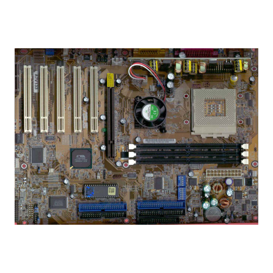
2. FEATURES 2.2.1 Component Locations 1110 ASUS A7V133 User’s Manual... -
Page 14: Hardware Setup
WOLCON AS99127F PCI Slot 5 IDELED USBPORT PANEL Audio Modem Riser (AMR) Grayed components are optional at the time of purchase ( is no longer neces- JTCPU sary on motherboards with PCB versions 1.02 and later) ASUS A7V133 User’s Manual... -
Page 15: Layout Contents
13) WOR p. 38 Wake-On-Ring Connector (2 pin) 14) PWR_, CPU_,CHA_FAN p. 39 Chassis, Power Supply, CPU, F_ Fan Connectors (3 pin) F_FAN 15) CD_IN, AUX p. 40 Internal Audio Connectors (Four 4-pin) (optional) MODEM continued... ASUS A7V133 User’s Manual... - Page 16 44 System Message LED (2 pin) 25) RESET (PANEL) p. 44 Reset Switch Lead (2 pin) 26) PWRSW (PANEL) p. 44 ATX / Soft-Off Switch Lead (2 pin) 27) SMI (PANEL) p. 44 System Management Interrupt Lead (2 pin) ASUS A7V133 User’s Manual...
-
Page 17: Hardware Setup Procedure
Failure to do so may cause severe damage to your motherboard, peripherals, and/or components. The onboard LED when lit acts as a reminder that the system is in suspend or soft-off mode and not powered OFF. Standby Powered Power A7V133 A7V133 Onboard LED ASUS A7V133 User’s Manual... - Page 18 (See #9 Voltage [1-2] Frequency Setting) Regulator Output) JumperFree™Mode All OFF All [3-4] [2-3] (Default) Jumper Mode JumperFree Mode (Default) See Frequency External Setting VID4 See Voltage Reg. VID3 Out. (VID) VID2 VID1 A7V133 A7V133 Jumper Mode Settings ASUS A7V133 User’s Manual...
- Page 19 NOTE: This setting is available only on motherboards with the onboard audio option. Setting AUDIOCODEC Enable [1-2] [1-2] [1-2] [1-2] (default) Disable [2-3] [2-3] [2-3] [2-3] Enable Disable Onboard Onboard Audio Codec Audio Codec (Default) ADN# ADN# AUD_EN2 AUD_EN2 AUD_EN1 AUD_EN1 A7V133 A7V133 Audio Codec Setting ASUS A7V133 User’s Manual...
- Page 20 The default setting is ATA100: [1-2] [1-2]. Setting ATA100/RAID 0 or 1 RAID 0 or 1 Jumper 13 [1-2] Jumper 14 [2-3] ATA100 Jumper 13 [1-2] Jumper 14 [1-2] JP13 JP14 RAID 0 or 1 ATA100 A7V133 (Default) A7V133 ATA100/RAID0 Selection ASUS A7V133 User’s Manual...
- Page 21 A7V133 VIO Setting WARNING! Using a higher voltage may help when overclocking but may re- sult in the shortening of your computer component’s life. It is strongly recom- mended that you leave this setting on its default. ASUS A7V133 User’s Manual...
- Page 22 Menu in BIOS Setup so you can set the CPU Frequency). WARNING! Frequencies other than the recommended CPU bus frequencies are not guaranteed to be stable. Overclocking your processor is not recommended. It may result in a slower speed and premature wearing of the processor. ASUS A7V133 User’s Manual...
- Page 23 2. To use this feature, JEN must be set to Jumper Mode: [1-2]; [See section 2]. 3. Processor speeds may be also be adjusted in JumperFree Mode using BIOS software. For more up to date processor settings, visit the ASUS web site (see ASUS CONTACT INFORMATION). ASUS A7V133 User’s Manual...
- Page 24 VID2 VID3 VID3 VID3 VID3 VID4 VID4 VID4 VID4 1.375/1.4Volts 1.325/1.35Volts 1.275/1.30Volts 1.225/1.25Volts VID1 VID1 VID1 VID1 VID2 VID2 VID2 VID2 VID3 VID3 VID3 VID3 VID4 VID4 VID4 VID4 1.175/1.20Volts 1.125/1.15Volts 1.075/1.10Volts CPU Default/ JumperFree (Default) ASUS A7V133 User’s Manual...
-
Page 25: System Memory (Dimm)
For the system CPU bus to operate at 100MHz/133MHz, use only PC100-/PC133- • compliant DIMMs. • ASUS motherboards support SPD (Serial Presence Detect) DIMMs. This is the memory of choice for best performance vs. stability. • SDRAM chips are generally thinner with higher pin density than EDO (Extended Data Output) chips. -
Page 26: Memory Installation
DIMM slot on the motherboard. You must tell your retailer the correct DIMM type before purchasing. This motherboard supports four clock signals per DIMM. ASUS A7V133 User’s Manual... -
Page 27: Central Processing Unit (Cpu)
CAUTION! Be careful not to scrape the motherboard surface when mounting a clamp-style processor fan or else damage may occur to the motherboard. BLANK LEVER LOCK AMD™ Athlon A7V133 A7V133 Socket A NOTCH ASUS A7V133 User’s Manual... -
Page 28: Expansion Cards
5. Replace the computer system’s cover. 6. Set up the BIOS if necessary (such as IRQ xx Used By Legacy Drive: Yes in 4.4.3 PCI Configuration) 7. Install the necessary software drivers for your expansion card. ASUS A7V133 User’s Manual... -
Page 29: Assigning Irqs For Expansion Cards
PCI slot 5 — — — shared AGP Pro slot shared shared — — Onboard USB controller — — — shared Onboard Audio/AMR — — shared — Onboard Promise IDE Controller — shared — — ASUS A7V133 User’s Manual... -
Page 30: Accelerated Graphics Port Pro (Agp Pro)
3.7.3 Accelerated Graphics Port Pro (AGP Pro) This motherboard provides an Accelerated Graphics Port Pro (AGP Pro) slot to sup- port AGP/AGP Pro graphics cards, such as an ASUS AGP-V6800DDR/64M. CAUTION! To avoid damaging your AGP/AGP Pro graphics card, your computer’s power supply should be unplugged before inserting your graphics card into the slot. -
Page 31: Audio Modem Riser (Amr) Slot
For availability, see your vendor or dealer. ASUS MR-1 Unlike that of standard cards, the component side of the specially-designed AMR card faces the motherboard’s expansion slots when the card is installed A7V133 A7V133 Audio Modem Riser (AMR) Slot ASUS A7V133 User’s Manual... - Page 32 3. HARDWARE SETUP (This page intentionally left blank.) ASUS A7V133 User’s Manual...
-
Page 33: External Connectors
This connection is for a standard keyboard using an PS/2 plug (mini DIN). This connector will not allow standard AT size (large DIN) keyboard plugs. You may use a DIN to mini DIN adapter on standard AT keyboards. PS/2 Keyboard (6-pin Female) ASUS A7V133 User’s Manual... - Page 34 5) Parallel Port Connector (Burgundy 25-pin PRINTER) You can enable the parallel port and choose the IRQ through Onboard Parallel Port (see 4.4.2 I/O Device Configuration). NOTE: Serial printers must be connected to the serial port. Parallel Port (25-pin Female) ASUS A7V133 User’s Manual...
- Page 35 (Pin 5 is removed to prevent inserting in the wrong orienta- tion when using ribbon cables with pin 5 plugged). FLOPPY NOTE: Orient the red markings on the floppy ribbon cable to PIN 1. PIN 1 A7V133 A7V133 Floppy Disk Drive Connector ASUS A7V133 User’s Manual...
- Page 36 UltraDMA66 and UltraDMA100 IDE devices require a 40-pin 80-conductor cable and RAID arrays only operate with such cables. A7V133 PIN 1 PIN 1 A7V133 IDE Connectors NOTE: Orient the red markings on the IDE ribbon cable to PIN 1. ASUS A7V133 User’s Manual...
- Page 37 Chassis Signal lead, which occurs when a panel switch or light detec- tor is triggered. This function requires the optional ASUS CIDB chassis intru- sion module to be installed (see 7. APPENDIX). If the chassis intrusion lead is not used, a jumper cap must be placed over the pins to close the circuit.
- Page 38 12) Wake-On-LAN Connector (3-pin WOL_CON) This connector connects to a LAN card with a Wake-On-LAN output, such as the ASUS PCI-L101 Ethernet card (see 7. Appendix). The connector powers up the system when a wakeup packet or signal is received through the LAN card.
- Page 39 NOTE: The “Rotation” signal is to be used only by a specially designed fan with rotation signal. The Rotations per Minute (RPM) can be monitored using ASUS PC Probe (see 6. SOFTWARE REFERENCE). The Rotation signal is not supported by F-FAN.
- Page 40 16) Internal Microphone Header (3-pin MIC2) This connector allows you to connect a chasssis mounted microphone to the mother- board instead of having to attach an external microphone onto the ATX connectors. MIC2 A7V133 A7V133 Microphone Header ASUS A7V133 User’s Manual...
- Page 41 SMBus devices. SMBus is a specific implementation of an I bus, which is a multi-device bus; that is, multiple chips can be connected to the same bus and each one can act as a master by initiating data transfer. A7V133 A7V133 SMBus Connector ASUS A7V133 User’s Manual...
- Page 42 A7V133 ATX Power Connector 20) Power Supply Thermal Sensor Connector (2-pin block JTPWR) If you have a power supply with thermal monitoring, connect its thermal sensor cable to this connector. JTPWR A7V133 A7V133 Power Supply Thermal Sensor Connector ASUS A7V133 User’s Manual...
- Page 43 Primary/Secondary IDE and Primary/ Secondary ATA100 connectors will cause the LED to light up. TIP: If the case-mounted LED does not light, try reversing the 2-pin plug. IDELED A7V133 A7V133 IDE Activity LED ASUS A7V133 User’s Manual...
- Page 44 This may require one or two presses depending on the position of the switch. Wake-up can be controlled by settings in the BIOS but the keyboard will always allow wake-up (the SMI lead cannot wake up the system). ASUS A7V133 User’s Manual...
-
Page 45: Starting Up The First Time
No DRAM installed or detected One long beep followed by Video card not found or video card three short beeps memory bad High frequency beeps when CPU overheated system is working System running at a lower frequency ASUS A7V133 User’s Manual... - Page 46 Shut Down, and then click Shut down the computer? The power supply should turn off after Windows shuts down. NOTE: The message “You can now safely turn off your computer” will not appear when shutting down with ATX power supplies. ASUS A7V133 User’s Manual...
-
Page 47: Bios Setup
4. In DOS mode, type A:\AFLASH <Enter> to run AFLASH. IMPORTANT! If “unknown” is displayed after Flash Memory:, the memory chip is either not programmable or is not supported by the ACPI BIOS and there- fore, cannot be programmed by the Flash Memory Writer utility. ASUS A7V133 User’s Manual... -
Page 48: Updating Bios Procedures
BIOS revision will solve your problems. Care- less updating can result in your motherboard having more problems! 1. Download an updated ASUS BIOS file from the Internet (WWW or FTP) (see ASUS CONTACT INFORMATION on page 3 for details) and save to the disk you created earlier. - Page 49 If the Flash Memory Writer utility was not able to successfully update a complete BIOS file, your system may not be able to boot up. If this happens, your system will need servicing. ASUS A7V133 User’s Manual...
-
Page 50: Bios Setup Program
To access the BIOS Setup program, press the <Delete> key after the computer has run through its POST. NOTE: Because the BIOS software is constantly being updated, the following BIOS screens and descriptions are for reference purposes only and may not exactly reflect your BIOS screens. ASUS A7V133 User’s Manual... -
Page 51: Bios Menu Bar
Use this menu to exit the current menu or specify how to exit the Setup program. To access the menu bar items, press the right or left arrow key on the keyboard until the desired item is highlighted. ASUS A7V133 User’s Manual... -
Page 52: Legend Bar
Brings up a selection menu for the highlighted field <Home> or <PgUp> Moves the cursor to the first field <End> or <PgDn> Moves the cursor to the last field <F5> Resets the current screen to its Setup Defaults <F10> Saves changes and exits Setup ASUS A7V133 User’s Manual... - Page 53 Item Specific Help window located to the right of each menu. This window displays the help text for the currently highlighted field. NOTE: The item heading in square brackets represents the default setting for that field. ASUS A7V133 User’s Manual...
-
Page 54: Main Menu
This is required to support older Japanese floppy drives. Floppy 3 Mode support will allow reading and writing of 1.2MB (as opposed to 1.44MB) on a 3.5-inch diskette. Configuration options: [Disabled] [Drive A] [Drive B] [Both] ASUS A7V133 User’s Manual... -
Page 55: Primary & Secondary Master/Slave
Primary IDE hard disk drives must have its partition set to active (also possible with FDISK). Other options for the Type field are: [None] - to disable IDE devices ASUS A7V133 User’s Manual... - Page 56 NOTE: To make changes to this field, the Type field must be set to [User Type HDD] and the Translation Method field must be set to [Manual]. ASUS A7V133 User’s Manual...
- Page 57 IDE devices. Set to [Disabled] to suppress Ultra DMA capa- bility. NOTE: To make changes to this field, the Type field must be set to [User Type HDD]. Configuration options: [0] [1] [2] [3] [4] [Disabled] ASUS A7V133 User’s Manual...
-
Page 58: Keyboard Features
[6/Sec] [8/Sec] [10/Sec] [12/Sec] [15/Sec] [20/Sec] [24/Sec] [30/Sec] Keyboard Auto-Repeat Delay [1/4 Sec] This field sets the time interval for displaying the first and second charac- ters. Configuration options: [1/4 Sec] [1/2 Sec] [3/4 Sec] [1 Sec] ASUS A7V133 User’s Manual... - Page 59 Configuration options: [All Errors] [No Error] [All but Keyboard] [All but Disk] [All but Disk/Keyboard] Installed Memory [XXX MB] This display-only field displays the amount of conventional memory detected by the system during bootup. You do not need to make changes to this field. ASUS A7V133 User’s Manual...
-
Page 60: Advanced Menu
CPU speed (the CPU’s inter- nal frequency). Selecting a frequency higher than what the CPU manufacturer recommends may cause the system to hang or crash. See System Hangup later in this section. ASUS A7V133 User’s Manual... - Page 61 If detected, IRQ12 will be used for the PS/2 mouse. IRQ12 will be reserved for expansion cards only if a PS/2 mouse is not detected. [Enabled] will always reserve IRQ12, whether on startup a PS/2 mouse is detected or not. Configuration options: [Enabled] [Auto] ASUS A7V133 User’s Manual...
- Page 62 OFF your system and restart. The system will start up in safe mode running at a DRAM-to-CPU frequency ratio of 3:3 and a bus speed of 100MHz. You will then be led to BIOS setup to adjust the configurations. ASUS A7V133 User’s Manual...
-
Page 63: Chip Configuration
AGP Drive Strenght N Ctrl [E] (When AGP 4X Drive Strength set to [Manual]) Configuration options: [0] [1] [2]...[F] AGP 4X Mode [4x] Configuration options: [4x] [2x] [1x] AGP Fast Write [Disabled] Configuration options: [Disabled] [Enabled] ASUS A7V133 User’s Manual... - Page 64 (bytes or words) into a single 32-bit block of data. However, byte merging may only be done when the bytes within a data phase are in a prefetchable address range. Configuration options: [Disabled] [Enabled] DRAM Read Latch Delay [Auto] Configuration options: [-0.01 ns] [0.75 ns]...[Auto] ASUS A7V133 User’s Manual...
- Page 65 It can greatly improve the dis- play speed by caching the display data. You must set this to UC (uncacheable) if your display card cannot support this feature; otherwise your system may not boot. Configuration options: [UC] [USWC] ASUS A7V133 User’s Manual...
-
Page 66: I/O Device Configuration
COM2 connec- tor, it will no longer work if you enable the infrared feature. See Standard and Con- sumer Infrared Module Connector in 3.8 External Connectors. Configuration op- tions: [Disabled] [Enabled] ASUS A7V133 User’s Manual... - Page 67 If you have conflicts with the onboard modem/audio controller, you may set the appro- priate field to [Disabled]. Configuration options: [Disabled] [Auto] ASUS A7V133 User’s Manual...
- Page 68 Enable this field if you want to use the MIDI device onboard. MPU 401 I/O Base Address [300h-303h] This sets the I/O address for the onboard MIDI device. FM Enable (388h-38Bh) [Disabled] This field enables or disables the FM modulation feature. ASUS A7V133 User’s Manual...
-
Page 69: Pci Configuration
PCI Latency Timer [32] Leave on default setting for best performance vs. stability. USB Function [Enabled] This motherboard supports Universal Serial Bus (USB) devices. Set to [En- abled] if you want to use USB devices. Configuration options: [Disabled] [Enabled] ASUS A7V133 User’s Manual... - Page 70 (non-PnP) device. The default value indi- cates either that the displayed IRQ is not used or that the legacy Configura- tion Utility (ICU) is being used to determine if a legacy device is using that IRQ. Configuration options: [No/ICU] [Yes] ASUS A7V133 User’s Manual...
- Page 71 (non-PnP) device. The default setting indicates either that the displayed DMA channel is not used or an ICU is being used to determine if a legacy device is using that channel. Configuration options: [No/ICU] [Yes] ASUS A7V133 User’s Manual...
- Page 72 8K, 16K, 32K, or 64K. If you are using an ICU to accomplish this task, leave Reserved MEM Block BASE to its default setting of [No/ICU]. Configu- ration options: [No/ICU] [C800] [CC00] [D000] [D400] [D800] [DC00] ASUS A7V133 User’s Manual...
-
Page 73: Shadow Configuration
ROMs on them, you will need to know which addresses the ROMs use to shadow them specifically. Shadowing a ROM reduces the memory available between 640K and 1024K by the amount used for this purpose. Configuration options: [Disabled] [Enabled] ASUS A7V133 User’s Manual... -
Page 74: Power Menu
Windows 3.x and Windows 95, you need to install Windows with the APM feature. For Windows 98 and later, APM is automatically installed. A battery and power cord icon labeled “Power Management” will appear in the “Control Panel.” Choose “Advanced” in the Power Management Properties dialog box. ASUS A7V133 User’s Manual... - Page 75 Select [ON] to make CPU Fan keep turning in Standby Mode. Configura- tion options: [ON] [OFF] Suspend Mode [Disabled] Sets the time period before the system goes into suspend mode. Configu- ration options: [Disabled] [30 Sec] [1 Min]... [40 Min] ASUS A7V133 User’s Manual...
-
Page 76: Power Up Control
Turning an external modem off and then back on while the computer is off causes an initialization string that will also cause the system to power on. Configuration options: [Disabled] [Enabled] ASUS A7V133 User’s Manual... - Page 77 [By Date]. NOTE: Automatic Power Up will not work if the system is powered down by operating sys- tems, such as Windows 98, that have ACPI support enabled. Configuration options: [Disabled] [Everyday] [By Date] ASUS A7V133 User’s Manual...
-
Page 78: Hardware Monitor
4. BIOS SETUP 4.5.2 Hardware Monitor MB Temperature [xxxC/xxxF] CPU Temperature [xxxC/xxxF] The ASUS onboard hardware monitor reports this temperature. It may be higher than those readings reported by external thermal sensors but reflects the CPU temperature more accuratelyHard_Monitor. JTPWR Temperature [xxxC/xxxF] Using a thermal sensor cable, user may monitor the temperature of any onboard device. -
Page 79: Boot Menu
Make sure the ATAPI CD-ROM drive that you want to use in the boot sequence is connected to either the PRIMARY or SECONDARY IDE con- nectors, not to the ATA100 connectors. Currently, the Promise® Ultra DMA/100 chip does not support this feature. ASUS A7V133 User’s Manual... - Page 80 40 or 80 tracks. Configuration options: [Disabled] [Enabled] SCSI/ATA100 Boot Sequence [ATA100/SCSI] Configuration options: [ATA100/SCSI] [SCSI/ATA100] Load Onboard ATA Bios [Auto] Configuration options: [Auto] [Disabled] Primary VGA Bios [PCI Card] Configuration options: [PCI Card] [AGP Card] ASUS A7V133 User’s Manual...
-
Page 81: Exit Menu
This option should only be used if you do not want to save the changes you have made to the Setup program. If you have made changes to fields other than system date, system time, and password, the system will ask for con- firmation before exiting. ASUS A7V133 User’s Manual... - Page 82 This option saves your selections without exiting the Setup program. You can then return to other menus and make changes. After selecting this op- tion, all selections are saved and a confirmation is requested. Select [Yes] to save any changes to the non-volatile RAM. ASUS A7V133 User’s Manual...
-
Page 83: Software Setup
NOTE: Because there are various motherboard settings, options, and expansion cards, the following can only be used as a general reference and may not reflect exactly the screen contents displayed on your screen. ASUS A7V133 User’s Manual... -
Page 84: A7V133 Series Motherboard Support Cd
Install ASUS PC Probe Vx.xx: Installs a smart utility to monitor your computer’s fan, temperature, and voltages. • ASUS Update Vx.xx: Instals a program that can help you update BIOS or down- load a BIOS image file. • YAMAHA Soft Synthesizer: (Optional) Installs the Yamaha SoftSynthesizer for playing MIDI files. - Page 85 Install Cyberlink Video and Audio Applications: Installs Cyberlink PowerPlayer SE, PowerDVD Trial, and Cyberlink VideoLive Mail. • ASUS Screen Saver: Installs a nifty ASUS screen saver. • Show Motherboard Information: Allows you to view information about your motherboard, such as product name, BIOS version, and CPU.
-
Page 86: Using The Promise ® Chip For Raid 0 And 1
(See Section 3.4.5, Hardware Setup: Motherboard Settings for information about changing the jumper cap IDE default settings to support ATA-100 instead of RAID 0 and 1.) ASUS A7V133 User’s Manual... -
Page 87: Installing The Hard Disks
Rebuild Array..[ 5 ] [ 5 ] Controller Configuration . . . [ 6 ] [ 6 ] [ Keys Available ] Press 1..6 to select Option [ESC] Exit ASUS A7V133 User’s Manual... -
Page 88: Creating A Raid 0 Array
OS from a CD; alternatively, with a bootable OS CD, you may install the new OS automatically. As you install the OS, the system always treats the RAID 0 array of hard disks as if they are a single drive unit. ASUS A7V133 User’s Manual... -
Page 89: Creating A Raid 1 Array
[ Please Select A Source Disk ] Channel:ID Drive Model Capacity (MB) 3077 1:Mas ST3322IA 1:Sla ST3322IA 3077 [ Keys Available ] [ ] Up [ ] Up [ ] Down [ ] Down [ESC] Exit [ESC] Exit [Enter] Select [Enter] Select ASUS A7V133 User’s Manual... - Page 90 The second warning, Offline, indicates that one hard disks in a striped array has failed, cannot be detected, or has become disconnected. In this case, adjust or replace the hard disk if necessary and rebuild data from a back-up source. ASUS A7V133 User’s Manual...
-
Page 91: Other Fastbuild Utility Commands
Mirror Critical Stripe Block: Not Available [ Select Drive for Rebuild ] Channel: ID Drive Model Capacity (MB) 1: Slave ST3322IA 3077 [ Keys Available ] [ ] Up [ ] Down [ESC] Exit [Enter] Select ASUS A7V133 User’s Manual... -
Page 92: Alternative Setups And Other Details
RAID protocol automatically formats both disks to use only up to the maximum write space available on the smaller of two different hard disks. End-to-End Cable Connection Use only the ends of cable connectors to avoid signal loss mid-stream. ASUS A7V133 User’s Manual... -
Page 93: Manual Installation Of Ide/Raid Drivers
4. Select the “PCI Mass Storage Controller” node and then click “Properties.” 6. Please select [General] page to reinstall driver or select [Driver] page to update the driver. 7. Follow the instruction to insert your Windows CD or ASUS support CD to install the driver. (Driver Location: {CD-ROM driver}:\Promise\Raid0or1\Win9x-ME) ®... -
Page 94: Software Reference
ASUS Utility, and then click Probe Vx.xx. The PC Probe icon will appear on the taskbar’s system tray indicating that ASUS PC Probe is running. Clicking the icon will allow you to see the status of your PC. ASUS A7V133 User’s Manual... - Page 95 6. SOFTWARE REFERENCE 6.1.2 Using ASUS PC Probe Monitoring Monitor Summary Shows a summary of the items being monitored. Temperature Monitor Shows the PC’s temperature (for supported processors only). Temperature Warning threshold adjustment (Move the slider up to increase the...
- Page 96 CPU temperature and predefined thresh- old. Information Hard Drives Shows the used and free space of the PC’s hard disk drives and the file allo- cation table or file system used. ASUS A7V133 User’s Manual...
- Page 97 CPU type, CPU speed, and in- ternal/external frequencies, and memory size. Utility Lets you run programs outside of the ASUS Probe modules. To run a program, click Execute Program. NOTE: This feature is currently unavailable. ASUS A7V133 User’s Manual...
- Page 98 6. SOFTWARE REFERENCE 6.1.3 ASUS PC Probe Task Bar Icon Right clicking the PC Probe icon will bring up a menu to open or exit ASUS PC Probe and pause or resume all sys- tem monitoring. When the ASUS PC Probe...
-
Page 99: Cyberlink Powerplayer Se
Backstep Frame Step Frame Previous Next Play Stop Configuration i-Power! Increase Volume CD Mode Mute Shuffle Decrease Volume Karaoke Next angle Next audio stream Next subtitle Add bookmark Capture frame Go-Up Repeat Menu Go to bookmark ASUS A7V133 User’s Manual... -
Page 100: Cyberlink Powerdvd
To start CyberLink PowerDVD, click the Windows Start button, point to Programs, and then CyberLink PowerDVD, and then click PowerDVD. 6.3.2 CyberLink PowerDVD User Interface Minimize Exit Main Display Control Full Screen / CD/File Control Help Eject Panel Wheel Video Window Mode (closed) Functions ASUS A7V133 User’s Manual... -
Page 101: Cyberlink Videolive Mail
VLM 3 supports all the hardware devices that are compliant with Video for Win- dows standard. Video for Windows is a well-accepted and well-tested standard. Thus, users do not have to worry about compatibility issues. ASUS A7V133 User’s Manual... - Page 102 Start Playback Save Video File Snapshot to File Stop Recording / Playback Send Mail Start Recording Video Configuration Load Video File Pause Send Mail Increase MIC volume Decrease MIC volume Increase speaker volume Decrease speaker volume ASUS A7V133 User’s Manual...