Table of Contents
Advertisement
Quick Links
Owner's Manual
Before using this unit, carefully read the sections entitled: "USING THE UNIT SAFELY"(p. 4) and
"IMPORTANT NOTES" (p. 6). These sections provide important information concerning the proper
operation of the unit. Additionally, in order to feel assured that you have gained a good grasp of every
feature provided by your new unit, owner's manual should be read in its entirety. The manual should be
saved and kept on hand as a convenient reference.
Copyright © 2011 ROLAND CORPORATION
All rights reserved. No part of this publication may be reproduced in any form without the written
permission of ROLAND CORPORATION.
* Roland is either registered trademark or trademark of Roland Corporation in the United States and/or other countries.
* All product names mentioned in this document are trademarks or registered trademarks of their respective owners.
Advertisement
Table of Contents

Related Manuals for Roland VR-3


Summary of Contents for Roland VR-3
- Page 1 All rights reserved. No part of this publication may be reproduced in any form without the written permission of ROLAND CORPORATION. * Roland is either registered trademark or trademark of Roland Corporation in the United States and/or other countries. * All product names mentioned in this document are trademarks or registered trademarks of their respective owners.
- Page 2 For the U.K. IMPORTANT: THE WIRES IN THIS MAINS LEAD ARE COLOURED IN ACCORDANCE WITH THE FOLLOWING CODE. BLUE: NEUTRAL BROWN: LIVE As the colours of the wires in the mains lead of this apparatus may not correspond with the coloured markings identifying the terminals in your plug, proceed as follows: The wire which is coloured BLUE must be connected to the terminal which is marked with the letter N or coloured BLACK.
-
Page 3: Check The Included Items
You can obtain the open source license source code used in this product by downloading it from the following website. http://www.roland.com/support/gpl/ MMP (Moore Microprocessor Portfolio) refers to a patent portfolio concerned with microprocessor architecture, which was developed by Technology Properties Limited (TPL). Roland has licensed this technology from the TPL Group. -
Page 4: Using The Unit Safely
Refer all servicing to your retailer, and headphones or speakers, may be capable of producing the nearest Roland Service Center, or an authorized Roland sound levels that could cause permanent hearing loss. Do distributor, as listed on the “Information” sheet. - Page 5 Before using the unit in a foreign country, consult with your accumulation of dust between the power plug and the retailer, the nearest Roland Service Center, or an authorized power outlet can result in poor insulation and lead to fire.
-
Page 6: Important Notes
Corporation will accept no responsibility for any such health problems that may occur in yourself • With the factory settings, the VR-3's power will automatically be or in viewers. switched off if all these 3 statuses continue 240 minutes. -
Page 7: Table Of Contents
Contents Power Supply ........................8 Connecting the AC Adapter ..............................8 Turning the Power On ................................9 Turning the Power Off ................................9 Names of Things and What They Do ................10 Top Panel....................................10 Audio Mixer Section..................................11 Video Select Section..................................12 Rear Panel....................................14 Left Side Panel ..................................15 Right Side Panel ..................................15... -
Page 8: Power Supply
(see figure) with an external ground. When the unit is grounded, a slight hum may occur, depending on the particulars of your installation. If you are unsure of the connection method, contact the nearest Roland Service Center, or an authorized Roland distributor, as listed on the "Information"... -
Page 9: Turning The Power On
VR-3 starts up. fig.power-button.eps Turning the Power Off Press the [POWER] button on the rear panel. The buttons and indicators on the top panel go dark, and the power to the VR-3 is switched off. About AUTO OFF When all of the conditions described below continue for 240 minutes or longer, the AUTO OFF feature automatically turns off power of the VR-3. -
Page 10: Names Of Things And What They Do
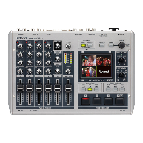
Names of Things and What They Do Top Panel fig.top-panel.eps 1. Audio Mixer Section (p. 11) This section is for audio mixing. Use the dials and faders to adjust the input sensitivity, output levels, and other values for each channel. 2. -
Page 11: Audio Mixer Section
Names of Things and What They Do Audio Mixer Section fig.audio-mix-section.eps 1. GAIN Dials and PEAK Indicators 7. INTERNAL MIC LEVEL Dial (p. 26) Use the [GAIN] dials to adjust the input sensitivity for This adjusts the level for the internal microphones. channels 1 through 4. -
Page 12: Video Select Section
This displays the inputs from the respective source devices. switch the inset screen or foreground picture. • [OUTPUT] This displays the result of video mixing on the VR-3 (the final 5. FREEZE Button (p. 24) output). Use this button to freeze the final output image. -
Page 13: Luminance Key
Names of Things and What They Do 8. KEY LEVEL Dial (p. 35, p. 37) This adjusts the degree of the extraction (removal) in key compositing. The extraction color for key compositing differs according to the direction in which you turn the dial. At the center position, no extraction at all occurs. (The background video is not visible.) Turning the dial all the way clockwise or counterclockwise enables complete extraction, and the foreground picture is not visible. -
Page 14: Rear Panel
* Use the cord hook to secure the AC adapter cord in place (p. 8). 3. USB Port You can use this to output the results of video and audio mixing on the VR-3 to a computer. 4. AUDIO OUTPUT Connectors These output the results of audio mixing. -
Page 15: Left Side Panel
1 through 4. Right Side Panel fig.left-side-panel.eps OUT/THRU MIDI IN and MIDI OUT/THRU connectors are equipped here. You can connect external MIDI devices to remote control the VR-3. Refer to “About Remote Control” (p. 48). Front Panel fig.front-panel.eps Two headphones (PHONES) connectors are located here. -
Page 16: Signal Flow
Names of Things and What They Do Signal Flow Signal flow inside the VR-3 is as shown in the figure below. fig.signal-flow.eps Converter Video Mixer PinP / Split / Key Video Fader Video Preview Audio Effects INT MIC Audio Mixer... -
Page 17: Connecting External Equipment
Connecting External Equipment You can connect external equipment as shown below. For information on specific connections, refer to the following pages. * To prevent malfunction and/or damage to speakers or other devices, always turn down the volume, and turn off the power on all devices before making any connections. -
Page 18: Connecting Video Sources
Connecting External Equipment Connecting Video Sources Connect video cameras, DVD players, and other sources to the VIDEO INPUT connectors. * Channel 4 has a composite connector and a RGB connector, and when input is made through both at the same time, the RGB input takes priority. fig.connect-video-source.eps Player Connecting Audio Sources... -
Page 19: Connecting Microphones
When you are connecting a dynamic microphone or other device that does not require power supply, be sure to set the [PHANTOM +48V] switch to OFF. Making the connection while the switch is left set to ON may cause malfunction. (Phantom power on the VR-3: +48 VDC/maximum 14 mA per channel) When one or both of the [PHANTOM +48V] switches is set to ON, current consumption increases by approximately 200 mA per switch. -
Page 20: Connecting A Computer
* The refresh rate is the maximum value of each resolution. The PC IN connector on the VR-3 is D-Sub 15-pin. If necessary, you can use a DVI-VGA adaptor to connect your DVI output to the D-Sub 15-pin connector. A DVI-VGA adapter is not included. Please purchase separately. -
Page 21: Connecting Output Equipment
Recorder Connecting an Amplifier, Speakers, and Recorders Connect an amplifier, speakers or a recorder to the AUDIO OUTPUT connectors. The VR-3 has standard TRS and RCA type AUDIO OUTPUT connectors, and the same audio is output from both types. * Nominal output level of the VR-3 is -10 dBu. Connect equipment that supports input at -10 dBu. -
Page 22: Basic Operation
Display the input from the sources. At [MONITOR], press the [INPUT] button. The input from the respective source is displayed at [1] through [4]. When the VR-3 starts up, [1] is selected, and a red border is displayed around the [1] section. - Page 23 Basic Operation Select a different channel. Touch the touch panel and choose a channel other than the one currently selected (the channel displayed with a red border). If you selected [MIX] or [WIPE] in step 2, the transition effect is applied. The newly selected channel is displayed with a green border while the transition effect is being applied.
-
Page 24: Automatically Switching The Video
When you are changing the connections between two computers during output, freeze the output before disconnecting the first computer and then end the freezing after connecting the second computer. This allows you to keep an active PC image on the screen while the VR-3 locks to the new PC source. -
Page 25: Adjusting The Audio Balance
Basic Operation Adjusting the Audio Balance When the [MASTER] fader is lowered all the way, no audio is output to the speakers or a computer connected via USB. For information on using the [MASTER] fader to adjust the final output, refer to “Adjusting the Final Audio Output” (p. 28). Adjusting the Input Sensitivity and Stereo Position Use the [GAIN] dials to adjust the input sensitivity and the [PAN] dial to adjust the stereo position. - Page 26 Using the internal microphones lets you mix the voices of nearby people or other ambient audio into the final output. The two internal microphones on the VR-3 are installed at the locations shown below. To adjust the level for the internal microphones, go to [INTERNAL MIC] and use the [LEVEL] dial.
- Page 27 Basic Operation Adjusting the Volume Balance for Each Channel Use the faders for 1 through 4 and for 5/6 to adjust the audio levels of the respective channels. * When audio is input from a computer via the stereo mini connector, it is assigned to channels 7/8. Channels 7/8 have no fader, and the dial is used for adjustment.
-
Page 28: Adjusting The Final Audio Output
Basic Operation Adjusting the Final Audio Output You can use the [MASTER] fader to adjust the volume level of the final output. Operate the fader while watching the [MASTER] indicator. Check the volume level of the final output. See the [MASTER] indicator to check the volume level. If [OVER] lights up, the volume level may be excessive, resulting in distortion. -
Page 29: Compositing The Picture
Compositing the Picture Compositing Using Picture-in-Picture Compositing that displays an inset screen on a background is called “Picture-in-Picture” (PinP). fig.PinP-complete.eps Inset Screen Background * By default, no shadows are added to the inset screen, but you can use the menus to add them. Go to the [VIDEO] menu, and at [PinP], adjust the setting value for [SHADOW]. - Page 30 Compositing the Picture Select the background. Use the touch panel to choose the channel for the background. A red border appears around the selected channel. fig.select-background.eps Select the inset screen. Use [VIDEO SELECT] buttons [1] through [4] to choose the channel for the inset screen. The indicator for the selected channel lights up in green.
-
Page 31: Adjusting The Position And Size Of The Inset Screen
Compositing the Picture Adjusting the Position and Size of the Inset Screen You can use the touch panel to adjust the position and size of the inset screen. Display the output picture on the monitor. At [MONITOR], press the [OUTPUT] button. Move the position of the inset screen. -
Page 32: Compositing Using Split
Compositing Using Split The four split composition patterns described below are available on the VR-3. * The names of the menu items are shown below. By default, “V. CENTER” is selected as the split pattern. You can use the menus to change this to a different pattern. - Page 33 Compositing the Picture On the monitor, display the inputs from the sources. At [MONITOR], press the [INPUT] button. Select the split mode. Go to [COMPOSITION] and press the [SPLIT] button to make it light up. [VIDEO SELECT] buttons [1] through [4] all simultaneously flash in green.
-
Page 34: Compositing Using Luminance Key/Chroma Key
Compositing the Picture Compositing Using Luminance Key/Chroma Key Compositing Using Luminance Key Luminance key enables you to superimpose logos or text on a background picture. In this section, the RGB input from a computer (channel 4) is composite over the video on channels 1 through 3. fig.lumi-key-sample.eps Black (or White) Luminance Key... - Page 35 Compositing the Picture Adjust the degree of extraction. Turn the [KEY-LEVEL] dial clockwise, toward [LUMI KEY], to adjust the amount of extraction. At the center position, no extraction at all occurs, and the background is not visible. Turning the dial clockwise all the way results in complete extraction, and the foreground logo/text cannot be seen.
-
Page 36: Compositing Using Chroma Key
Compositing the Picture Compositing Using Chroma Key Chroma key composites the video image shot with blue-back/green-back on a different background video. fig.chroma-key-sample.eps Blue (or Green) Chroma Key When using chroma key, you can specify either blue or green as the extraction color. By default, blue is extracted. You can use the menus to change the extraction color to green. - Page 37 Compositing the Picture Adjust the degree of extraction. Turn the [KEY-LEVEL] dial counterclockwise, toward [CHR KEY], to adjust the amount of extraction. At the center position, no extraction at all occurs, and the background is not visible. Turning the dial counterclockwise all the way results in complete extraction, and the foreground picture cannot be seen.
-
Page 38: Performing Output From The Usb Port
Performing Output from the USB Port Connecting a Computer You can connect a computer to the USB port on the VR-3 and output the results of video and audio mixing. fig.internet-out.eps Supported Operating Systems You can make connections to computers running the following operating systems. -
Page 39: Making The Connection To A Computer
After starting the VR-3 and the operating system on the computer, use the included USB cable to connect the USB port on the VR- 3 to a USB port on the computer. * Making the connection via an extension cable or USB hub may result in failure of the computer to detect the VR-3. Connect the VR-3 and computer directly. -
Page 40: Performing Output To A Computer
You can use the menus to apply delay to the audio output from the USB connector and align the timing of the video and the audio. On the VR-3, you can set the amounts of delay separately for the USB output and the analog output. Go to the [SYSTEM] menu, and at [AUDIO DELAY], adjust the values for [ANALOG OUT DELAY] and [USB OUT DELAY]. -
Page 41: Using Other Features
In addition to the effects just described, you can apply [AUDIO DELAY] to delay audio output in order to align the timing of the video and the audio. On the VR-3, you can set the amount of delay independently for analog output and USB output. Go to the [SYSTEM] menu, and at [AUDIO... - Page 42 Using Other Features Access the menu. Press the [MENU] button to display the menu on the monitor. fig.open-menu.eps Display the AUDIO menu. Touch the [AUDIO] icon on the right side to display audio-related menus. fig.audio-mix-menu.eps Select the target for the effect. Touch the icons arranged along the bottom of the screen to choose the target for applying the effect.
-
Page 43: Saving/Recalling Settings
Go to the [SYSTEM] menu and use [NTSC/PAL] to select [NTSC] or [PAL]. Restart the VR-3 to switch NTSC/PAL Images will not be display correctly if the setting on the VR-3 differs from the signals of the connected external equipment. -
Page 44: Menu Operations And Menu List
Menu Operations and Menu List Menu Operations Use the [MENU] button and the [VALUE] dial, or the touch screen to make various settings. Access the menu. Press the [MENU] button to call up the menu screen on the monitor. Displayed first is the top menu screen. From here, you can move to the screens for various items. -
Page 45: Menu List
Menu Operations and Menu List Change the setting value. Selecting a parameter and turning the [VALUE] dial changes the setting value. Press the dial to apply the setting. * You can change a setting value up or down by 10 units at a time by pressing down the dial as you turn it. fig.value-dial.eps Go back to the original screen. - Page 46 Menu Operations and Menu List AUDIO Menu Here you make settings related to audio effects. fig.audio-mix-menu.eps HIGH PASS / IN 1 This switches the high-pass filter for channel 1 on and off. HIGH PASS / IN 2 This switches the high-pass filter for channel 2 on and off. HIGH PASS / IN 3 This switches the high-pass filter for channel 3 on and off.
-
Page 47: System Menu
Menu Operations and Menu List SYSTEM Menu Here you make various system settings for the VR-3. fig.system-menu.eps PC IN H.POSITION This adjusts the horizontal location of computer input. V.POSITION This adjusts the vertical location of computer input. * The maximum location values differ depending on the size values. -
Page 48: Appendices
Roland website. http://www.roland.co.jp/solution/ fig.MVC-logo.eps The VR-3 can be operated remotely from a device that supports MIDI Visual Control. MIDI Visual Control is a feature that uses MIDI to link visual expression to a musical performance. -
Page 49: Troubleshooting
A logo cannot be input from a computer. Is the RGB output from the computer at a resolution supported by the VR-3? RGB signals at a resolution that the VR-3 does not support cannot be input correctly. For supported resolutions, check “Main Specifications.”... -
Page 50: Dimensions
Appendices Dimensions fig.dimension.eps Unit : mm 80.3 66.6 50.2... - Page 51 Memo...
- Page 52 Memo...
- Page 53 Index Ambient Sound ................26 PAL ..................... 43 amplifier ..................21 PAN ..................... 11, 26 Audio Mixer ................10, 19 PHANTOM ..................15 AUTO OFF ..................9 PHONES ..................11, 15 Picture-in-Picture ................29 PinP ..................... 13, 29 PREVIEW ................... 21 CHR KEY ...................
- Page 54 For EU Countries This product complies with the requirements of EMC Directive 2004/108/EC. For the USA FEDERAL COMMUNICATIONS COMMISSION RADIO FREQUENCY INTERFERENCE STATEMENT This equipment has been tested and found to comply with the limits for a Class B digital device, pursuant to Part 15 of the FCC Rules.
- Page 55 VR-3 AV MIXER For China...