Lennox Hearth Products CI1500DVF Installation Instructions Manual
Direct-vent serefina series
Hide thumbs
Also See for CI1500DVF:
- Care and operation instructions manual (26 pages) ,
- Homeowner's care and operation instructions manual (20 pages) ,
- Installation instructions manual (18 pages)
Table of Contents
Advertisement
P/N 775,147M REV. E 03/2010
Portland
US
Ce manuel d'installation est disponible en francais, simplement en faire la
demande. Numéro de la pièce 775,147CF.
WARNING
HOT GLASS WILL
CAUSE BURNS.
DO NOT TOUCH GLASS
UNTIL COOLED.
NEVER ALLOW CHILDREN TO
TOUCH GLASS.
This appliance may be installed in an aftermarket permanently located, manufactured home (USA only) or mobile
home, where not prohibited by local codes. This appliance is only for use with the type of gas indicated on the rating
plate. This appliance is not convertible for use with other gases, unless a certified kit is used.
WARNING: If the information in these instructions is
not followed exactly, a fire or explosion may result
causing property damage, personal injury or death.
- Do not store or use gasoline or other flammable vapors and
liquids in the vicinity of this or any other appliance.
- WHAT TO DO IF YOU SMELL GAS
• Do not try to light any appliance.
• Do not touch any electrical switch; do not use any
phone in your building.
• Immediately call your gas supplier from a neighbor's
phone. Follow the gas supplier's instructions.
• If you cannot reach your gas supplier, call the fire
department.
- Installation and service must be performed by a quali-
fied installer, service agency or the gas supplier.
INSTALLER: Leave this manual with the appliance.
CONSUMER: Retain this manual for future reference.
INSTALLATEUR: Laissez cette notice avec l'appareil.
CONSOMMATEUR: Conservez cette notice pour consul-
tation ultérieure.
OTL Report No. 116-S-08-5
INSTALLATION INSTRUCTIONS
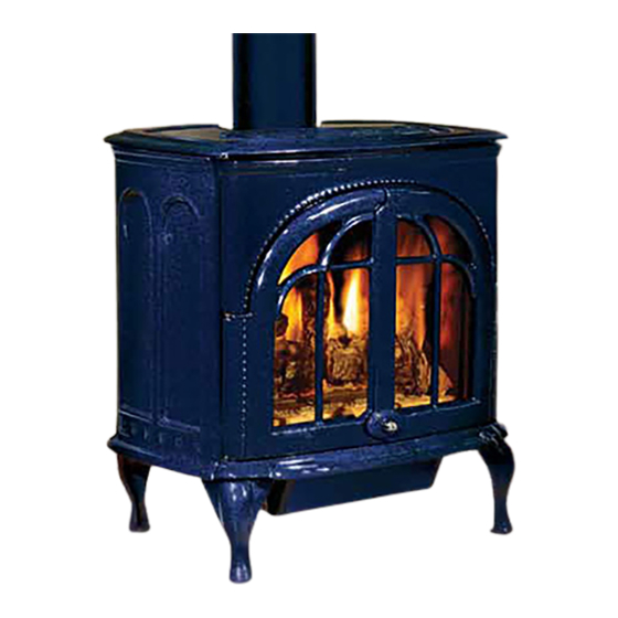
Direct-Vent
SEREFINA™ SERIES
MODELS
CI1500DVF
AVERTISSEMENT
UNE SURFACE VITRÉE CHAUDE PEUT
NE PERMETTEZ JAMAIS À UN ENFANT
DE TOUCHER LA SURFACE VITRÉE.
AVERTISSEMENT: Assurez-vous de bien suivre les
instructions données dans cette notice pour réduire
au minimum le risque d'incindie ou d'explosion ou
pour éviter tout dommage matériel, toute blessure
ou la mort.
- Ne pas entreposer ni utilizer d'essence ni d'autres
vapeurs ou liquides inflammables dans le voisinage
de cet appareil ou de tout autre appareil.
- QUE FAIRE SI VOUS SENTEZ UNE ODEUR DE GAZ:
• Ne pas tenter d'allumer d'appareil.
• Ne touchez à aucan interrupteur. Ne pas vous servir
des téléphones se trouvant dans le bâtiment où vous
trouvez.
• Appelez immédiatement votre fournisseur de gaz
depuis un voisin. Suivez les instructions du fournis-
seur.
• Si vous ne pouvez rejoindre le fournisseur de gaz,
appelez le service des incindies.
- L'installation et l'entretien doivent être assurés par un
installateur ou un service d'entretien qualifié ou par
le fournisseur de gaz.
CI2500DVF
CAUSER DES BRÛLURES.
LAISSER REFROIDIR LA SURFACE
VITRÉE AVANT D'Y TOUCHER.
Advertisement
Table of Contents

Related Manuals for Lennox Hearth Products CI1500DVF


Summary of Contents for Lennox Hearth Products CI1500DVF
-
Page 1: Installation Instructions
INSTALLATION INSTRUCTIONS Direct-Vent SEREFINA™ SERIES P/N 775,147M REV. E 03/2010 MODELS Portland OTL Report No. 116-S-08-5 CI1500DVF CI2500DVF Ce manuel d’installation est disponible en francais, simplement en faire la demande. Numéro de la pièce 775,147CF. WARNING AVERTISSEMENT HOT GLASS WILL UNE SURFACE VITRÉE CHAUDE PEUT... -
Page 2: Table Of Contents
TABLE OF CONTENTS PACKAGING LIST Packaging ................Page 2 Introduction ............... Page 2 The assembled vented gas stove heater is packaged with: Safety and Warning Information ........Page 3 one - log set located in firebox General Information ............Page 5 one - ember strip located beneath stove High Altitude .............. -
Page 3: Safety And Warning Information
IMPORTANT SAFETY AND WARNING AVERTISSEMENT INFORMATION On ne devrait pas placer de vêtements ni d’autres matières inflammables sur l’appareil ni à prox- imité. WARNING Young children should be carefully supervised when they are in the same room as the appliance. Tod- WARNING dlers, young children and others may be susceptible Any safety screen or guard removed for servicing... - Page 4 T hese appliances are vented gas appliances. Do not burn wood F OR YOUR SAFETY do not install or operate this appliance without or other material in these appliances. first reading and understanding this manual. Any installation or operation of the appliance deviating from that which is stated T his appliance is only for use with the type of gas indicated on in this manual WILL void the warranty and may be hazardous.
-
Page 5: General Information
Model Natural Propane Elevation Provide adequate clearances around air openings and adequate acces- Feet (meters) sibility clearance for service and proper operation. Never obstruct the CI1500DVF #37 (.104") 1.55mm (.061") 0-4500 (0-1372) front openings of the appliance. CI2500DVF .121" 1.75mm (.068") -
Page 6: Location
Considerations Should Include: WARNING: This appliance must be properly connected to a venting • Existing Chimneys system. Operation of this gas appliance when not connected to a properly installed and maintained venting system can result in • Aesthetic Considerations carbon monoxide (CO) poisoning and possible death. •... -
Page 7: Specifications
SPECIFICATIONS: Serefina™ Dimensions CI1500DVF CI2500DVF 24-1/2” (622 mm) 30-1/2” (775 mm) 27-1/2” (699 mm) 28-1/2” (724 mm) 19” (483 mm) 22” (559 mm) 7” (178 mm) 7” (178 mm) 20-1/2” (521 mm) 23-1/2” (597 mm) (with ashlip) 6” (152 mm) 6”... -
Page 8: Appliance And Vent Clearances
* Dimensions with a single asterix are reference dimensions only. ** If the optional warming shelves are installed, a greater alcove width is required as follows: CI1500DVF - 44" (1118 mm) min. CI2500DVF - 52-1/2" (1334 mm) min. Figure 2B ***This includes any projections such as shelves, windowsills, mantels, etc. -
Page 9: Manufactured Home Requirements
MANUFACTURED (MOBILE) HOME REQUIREMENTS TERMINATION HEIGHTS FOR VENTS ABOVE FLAT OR SLOPED ROOFS Horizontal Overhang These models may be installed in an aftermarket permanently located, manufactured home, where not prohibited by local codes. 2 FT Vertical MIN. 2 FT MIN. Wall When installed in Manufactured Housing the following supplemental Lowest... - Page 10 EXTERIOR HORIZONTAL VENT TERMINATION CLEARANCE REQUIREMENTS * See Item D in the Text Below. Center Line Exterior Wall Inside of Termination Corner Detail *18” Horizontal Termination 18” Ventilated Soffit Inside Corner = 9" in U.S. � = 12" in Canada DETAIL D 3 ft.
-
Page 11: Typical Installation Sequence
The gas supply line should be plumbed from the fuel source to the WARNING area where the appliance is to be installed per requirements outlined in NFPA 54 - latest edition (USA) and CAN/CSA-B149.1 - latest edi- Failure to position the parts in accordance with these tion (Canada). -
Page 12: Step 4 Remove Front Glass
Note: Install Leg Leveling Bolts if Necessary: The four leg leveling bolts Remove the front glass enclosure from stove as follows: (included in literature package), are provided for leveling the stove if necessary. To install, thread the bolts into the existing holes in the bottom A. -
Page 13: Step 5 Remove Firebox Contents
Step 5: REMOVE MATERIALS FROM FIREBOX - Remove the packaged CAUTION: Label all wires prior to disconnection when servic- materials from inside of the firebox and set aside (propane conversion ing controls. Wiring errors can cause improper and dangerous kit, log support cartons, log set and embers). operation. -
Page 14: Step 8 Install Lower Access Door
Wiring - Optional Forced Air Blower Kit: Step 8: INSTALL LOWER ACCESS DOOR . BK-CI (see Figure 11 for wiring diagram) - (An optional field-provided Install the lower access door by inserting the tabs on the door sides outletbox/J-Box may also be used). Install the blower kit according to into the corresponding holes on the brackets on the stove bottom the installation instructions provided with the kit. - Page 15 Vertical Termination Horizontal Termination The vent must rise vertically, a minimum of 24" (610 mm) off the A vertical vent system must terminate no less than 8 feet ( 2.44 meters) top of the appliance for Natural Gas and 36" for Propane Gas before and no more than 40 feet / 12 meters ( above the appliance flue collar.
- Page 16 The chimney conversion should not be applied to the portion of the vent Installing Support Brackets system that is in the room of the appliance. Use only Co-Axial direct- vent pipe (4” inner pipe, 6 5/8” outer pipe as listed on Page 17) from the Install support brackets per vent manufacturers instructions.
- Page 17 DIRECT-VENT SYSTEM COMPONENTS The following "Security Secure Vent " or "Simpson Dura-Vent" brand Direct-Vent components may be safely used with these appliances. IMPORTANT NOTE: Seal the first section of pipe to the stove collar using mill-pac black, high temperature sealant. Model # SECURITY SECURE-VENT - Description Model #...
-
Page 18: Step 10 Connect Gas Line
Step 10. CONNECTING GAS LINE When first lighting the appliance, it will take a few minutes for the line to purge air from the appliance. Once purging is complete, the pilot and burner will light and operate as indicated in the instruction manual. Subsequent lightings of the appliance will not require such purging. - Page 19 5. Install the right front log onto the corresponding burner pin and Note: If an optional Brick Liner Kit was purchased, install it now, per instruc- tions provided in kit sub-floor right tab as shown in Figure 24. 2. Place the largest log onto the rear log stoppers (see Figure 20). Ensure that the grooves on the bottom of the log aligns onto the cor- responding places on the rear log stoppers.
-
Page 20: Step 12 Reinstall Front Glass
8. Install the front right twig onto the corresponding pin on the right front log. Align the twig with the indentation on the front right log as shown in Figure 27. Right Front Twig DO NOT PLACE EMBERS ON TOP OF THE BURNER SLOTS. Figure 29 VERIFY THAT THE GAS LINE HAS BEEN PURGED OF AIR (SEE STEP 10). -
Page 21: Step 14 Check Appliance Operation
Step 14. CHECKING APPLIANCE OPERATION Step 15. BURNER ADJUSTMENTS With gas line installed run initial system checkout before closing up Flame Appearance and Sooting the front of the unit. Follow the pilot lighting instructions provided in the Homeowner's Care and Operation Instructions (or pull out the Proper flame appearance is a matter of taste. -
Page 22: Step 16 Install Top, Trivet & Ash Lip
Opening Setting - Inches (millimeter) Model Natural Propane Figure 35 5/16" 5/8" CI1500DVF (7.93 mm) (15.9 mm) B. Locate the ash lip from packaging (Step 2). Remove the 2 bolts from 1/2" 5/8" CI2500DVF the tapped holes in the ash lip. Align the ash lip below the firebox as (12.7 mm) -
Page 23: Step 17. Attaching Safety In Operation Warnings
3. Si no puede encontrar las etiquetas, sírvase llamar Lennox Hearth Products or your nearest Lennox taire. En cas de doute, collez l’étiquette en anglais. a Lennox Hearth Products o al distribuidor de Hearth Products dealer to receive additional 3. Si vous ne trouvez pas les étiquettes, veuillez Lennox Hearth Products más cercano para recibir... -
Page 24: Rating Plates
PROFONDEUR D'ALCÔVE MAXIMALE 1219.2mm 6/24/03 T-2185: MODEL WAS CI1500DVF DIRECT VENT GAS STOVE / APPAREIL A GAZ AVEC EVACUATION DIRECTE DIRECT VENT GAS STOVE / APPAREIL A GAZ AVEC EVACUATION DIRECTE VENTED GAS STOVE HEATER – NOT FOR USE WITH SOLID FUEL. - Page 25 NOTES...
- Page 26 Consult your local distributor for fireplace code information. Printed in U.S.A. © 2003 Lennox Hearth Products P/N 775,147M REV. E 03/2010 1508 Elm Hill Pike, Suite 108 • Nashville, TN 37210...