Table of Contents
Advertisement
Save These Instructions
For Future Reference
P/N 775226M, Rev. C, 11/2010
Portland
US
Report No. 116-S-53-2
INSTALLATION AND OPERATION MANUAL
Free-Standing
Pellet Stove
A French manual is available upon request. Order P/N 775226CF.
Ce manuel d'installation est disponible en francais, simplement en faire la demande. Numéro de la pièce
775226CF.
This appliance must be properly installed and operated in order to prevent the possibility
of a house fire. Please read this entire manual before installation and use of this
•
Hot! Do not touch! The glass and surfaces of this appliance will be
hot during operation and will retain heat for a while after shutting off
the appliance. Severe burns may result.
•
Carefully supervise children in the same room as appliance.
•
Lennox Hearth Products pellet-burning appliances are designed for
use as a supplemental heater. They are not intended for continuous
use as a primary heat source.
pellet fuel-burning room heater. Failure to follow these instructions could result
in property damage, bodily injury or even death. Contact your local building
or fire officials to obtain a permit and information on any installation
requirements and inspection requirements in your area.
WARNINGS
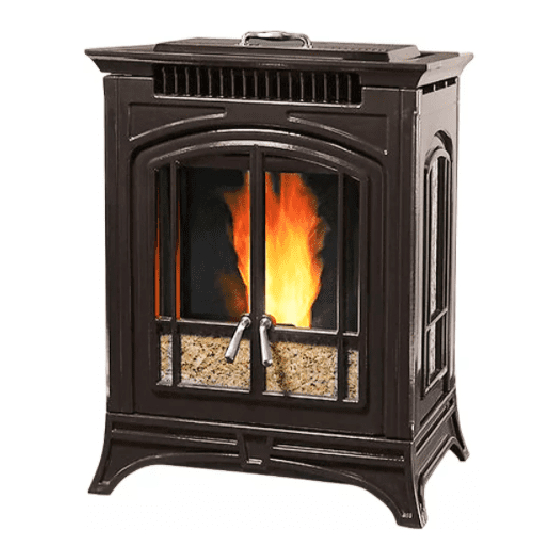
Pellet Stove
Model Bella™
Advertisement
Table of Contents

Related Manuals for Lennox Hearth Products Bella


Summary of Contents for Lennox Hearth Products Bella
- Page 1 Severe burns may result. • Carefully supervise children in the same room as appliance. • Lennox Hearth Products pellet-burning appliances are designed for use as a supplemental heater. They are not intended for continuous use as a primary heat source.
-
Page 2: Important Safety Information
Failure to comply with this restriction will void all warranties and the safety listing of the stove. Consult with your Lennox Hearth Products Improper installation, adjustment, alteration, ser- dealer for more information on approved pellet fuels. -
Page 3: Table Of Contents
Listing: The listing laboratory is OMNI-Test Laboratories, Inc., Port- thousands of individuals whose answer to their home heating needs land, Oregon. The report number is 116-S-53-2 for model Bella pellet reflects their concern for aesthetics, efficiency and our environment. stove. -
Page 4: Selecting A Location
Lennox Hearth Products accepts no liability for plugged directly into a properly grounded three-prong damages resulting from negative pressures described here. -
Page 5: Clearances
Corner Installations - Clearance to Combustibles 0*” (0 mm) Combustible Wall Back 3-1/2” (89mm) 3*” (76mm) 3” 3” Top View (76mm) (76mm) Min. Min. Top View Front Floor Protector 6” (152mm) Min. 3-1/2” (89mm) *Note: Refer to Page 4 for chimney/venting floor protection *Note: Refer to pipe Manufacturer's installation instructions requirements and recommendations. - Page 6 Corner Installations - Clearance to Combustibles 8-11/16” Horizontal Vent (221mm) Combustible Wall Combustible Wall 3-1/2” (89mm) 2” (51mm) Vertical Vent 3*” (76mm) Top View Top View 5” 5” (127mm) (127mm) 3-1/2” (89mm) Figure 6 - Horizontal Vent, Parallel or Alcove *Note: Refer to pipe Manufacturer's installation instructions for minimum pipe clearances. Alcove Installations - Clearance to Combustibles Figure 4 - Vertical Venting Minimum clearance from back of stove to back wall = 2 inches...
-
Page 7: Installation Tips
INSTALLATION TIPS INSTALLATION TIPS Select Your Installation Type GOOD INSTALLATION * BETTER INSTALLATION BEST INSTALLATION Horizontal Installation Vertical & Horizontal Installation Vertical Installation (Direct Vent - Outside Wall) (Up and Out) (Straight Up) No natural draft. Wind Some natural draft aids venting. Wind Natural draft improves operation and pressures may affect operation pressures may still affect operation... -
Page 8: Manufactured Home Installation
Lag Screw be used. Bracket • Connecting the Bella™ stove to outside combustion air is required in manufactured home installations and when required by local building codes. An outside air inlet must be provided for combustion and be unrestricted while unit is in use. Use a galvanized or stainless steel pipe for the duct (the outside air inlet on the stove is 3”... -
Page 9: Installation
Installation of Leg Leveling Bolts INSTALLATION An optional leg leveling kit is available. In manufactured home instal- lations a leg bolt down kit is also required (provided with stove). Install Removing Appliance From Pallet the leveling legs per the instructions provided in kit. See Figure 11 and Page 41 for leveling leg kit ordering information. - Page 10 Draft Adjuster - Adjustment Procedure Installation Check List The Bella™ pellet stove has a draft adjuster located at the left side of the It is strongly recommended that you have an Lennox Hearth Products stove directly in front of the combustion blower. Should the stove instal- dealer install your stove.
- Page 11 Thermostat installation Lack of Combustion Air: The Bella pellet stove can be operated manually or by thermostat. The By opening the draft adjuster, this will increase combustion air delivery. stove comes from the factory wired to operate manually - see control Symptoms of insufficient combustion air include;...
-
Page 12: Venting Requirements
Silicone sealant and three screws are required to secure the first vent connection to the appliance flue collar. Secure the remaining vent sections It is recommended that only an Lennox Hearth Products dealer install your using (3) three screws minimum per section, unless otherwise specified pellet stove. - Page 13 Vent Termination Locations Air Supply Inlet Vent Terminal Vertical Terminal Area Where Terminal Is Not Permitted USA - 1' Min. 24” (610mm) CANADA - 3' Min. Vertical Terminal (From Eave) USA - 1' Min. 24” CANADA - 3' Min. (610mm) Fixed Closed NOTE: Vent requirements are in accor- dance with NFPA 211 and CAN/CSA-...
- Page 14 Chimney Height Requirements - Site Built Residential Home To pass inspection in nearly any jurisdiction, the chimney must meet both safety and exhaust flow requirements. The (3’ by) 2’ by 10’ rule applies to both masonry and factory-built chimneys. The vent termination height required is - USA, 1-foot minimum; Canada 3-feet minimum above the roof penetration point as illustrated below (Ref.
- Page 15 90° Elbows/ 5 Feet (1.5 m) Tee (A & G) 45° Elbows 3 Feet (1 m) NOTE: All equivalent pipe styles shown for model Bella™ pellet stove. Horizontal 1 Feet (.3 m) (B & F) Vertical (E) .5 Feet (.15 m)
- Page 16 The Inlet shall remain free of obstruction while unit is in operation and constructed in a manner so as to prevent Installing the Bella™ Pellet Stove material from dropping into the inlet or into the area beneath the dwelling.
- Page 17 Vent Configurations Listed Rain Cap (all installations) A vertical run of 6 feet Exterior is recommended Vertical Vent 45° 90° Clean-Out Clean-Out Figure 24 - Horizontal and Up Through the Eave Figure 22 - Horizontal and Up 6 Feet Listed Rain Cap (all installations) Interior Vertical Vent into an Exist- ing Class A Chimney Horizontal installations that terminate without any vertical sections of pipe are approved;...
- Page 18 Masonry Chimney Fireplace When venting into a masonry chimney, the pellet pipe can terminate just When venting into a fireplace chimney, the pellet pipe can terminate just inside the chimney. However, it is recommended to run the pellet pipe to above the damper.
-
Page 19: Care And Operation
CARE AND OPERATION Simple Operating Instructions 1. Start FIRST TIME USE 2. Preparation 3. Priming the Auger 5. To Start Your Stove 7. Once the ignition sequence (Optional) is complete, the stove will a] Check hopper and remove enter "heating" mode and any materials from hopper a] Fill hopper with pellets a] Check hopper, and fill with... - Page 20 4-5 minutes to make sure there is a sustainable fire after refueling. IGNITION / HEAT CONTROL NOTE: This is an exclusive feature of the Bella™ to assure the highest reliability, safety and convenience. HIGH...
- Page 21 Manual Operation 3. The hopper lid switch circuit is open which indicates the hopper lid is not properly closed during the ignition sequence. If the hopper lid remains open, After the stove is burning (see lighting instructions on Page 19), the heat the shutdown cycle will start within the time indicated on the display screen.
- Page 22 LCD Display Screen - Cold Shutdown Screens 8 THERMOSTAT OFF COOL-DOWN 13 HEAT SWITCH OFF SHUTDOWN % % % % 8. The thermostat has not called for heat for over an hour, the stove has completed it's thermostat low burn idle and has entered into the COOL DOWN mode which will be followed by the FINAL SHUTDOWN mode.
- Page 23 19 NO FIRE SHUTDOWN 25 AUGER JAM ERROR 25. The stove was unable to clear an obstruction in the auger or drop tube, the 19. Your stove's proof of fire switch has failed to detect fire, the stove has completed COOL DOWN and SHUT DOWN modes have been completed and the stove it's COOL DOWN mode and is in the process of shutting down.
-
Page 24: Fuel
Young children should be carefully supervised when less than ten seconds the stove will continue to operate normally when they are in the same room as the Bella pellet stove. Clothing or power resumes. If electrical power is interrupted for more than ten sec-... -
Page 25: Routine Maintenance
Shelled corn can be burned in the Bella pellet stove when it is mixed with Opening the Glass Door wood pellet fuel. The mixture can contain a maximum of 50 percent corn. - Page 26 Figure 31 - Opening Front Door Opening Right Side Door Unlike the front and left side doors which are held in the closed position by magnets, the right side door is fastened from the inside to assure there is no interference when opening the front door. CAUTION; read and understand the steps below and open the right side door with care.
- Page 27 Ash Pots Removal and Cleaning Burn-Pot Cleaning (Recommended Frequency of 2 Days - 2 Weeks*) (Recommended Frequency of 1 – 2 days*) The combustion blower comes on at high speed once an hour to blow NOTE: If an optional log set is installed, carefully remove logs before the by-products of combustion out of the Burn-Pot.
- Page 28 Inspect Gaskets (Recommended Frequency of Yearly*) Inspect the condition of the rope gasket around the door and window periodically, and replace if necessary. Cleaning the Heat Exchanger (Recommended Frequency of 2 Days - 2 Weeks*) CAUTION: Do not operate the heat exchange scraper when the stove is hot.
- Page 29 Lower Main Cover Figure 39 Rear Cover Removal Figure 40 There are three removable covers on the rear of the stove. For normal maintenance, the lower main cover (Figure 40) should yield sufficient access to all necessary components. It may be necessary to remove the lower side and bottom covers for the initial installation.
- Page 30 Small Area Touch-up Paint Models with Black Painted Finish Rain Cap The stove body is painted with a quality high-temperature stove paint. (Minimum Frequency of 1-2 months) Use only stove touch-up paint shown below. Do not touch-up your stove with any other paint...
-
Page 31: Specifications
Convection (room air) SPECIFICATIONS - Bella™ Blower 150 CFM; .90 Amps, 1650 rpm Product Reference Information Combustion Blower 100 CFM: 1.3 Amps, 3000 rpm Ship. Ship. Cat. No. Model Description Weight Volume Auger Motor 1.28 RPM; .4 Amps H3480 BELLA-B Bella, Black Cast 411 lb. -
Page 32: Component Definitions
Your Bella™ pellet stove can be powered with a gas driven electrical gen- • Low Limit Proof of Fire Snap Switch (Ceramic, F140-10F, N/O*) erator. -
Page 33: Wiring Diagram
Bella = FEMALE DISCONNECT ™ = MALE DISCONNECT = STUD CONNECTION Wire Diagram N/C = NORMALLY CLOSED N/O = NORMALLY OPEN Power Wiring Harness - DC Auger To Controller AC Power Connector (8 pin Male) Stove 1 2 3 4 5 6 7 8... -
Page 34: Troubleshooting
TROUBLESHOOTING QUALIFIED TECHNICIANS ONLY Unplug Appliance Before Performing Any Troubleshooting or Maintenance Ignition/Proof of Fire Failure - Message - No Fire Error Possible Problem Solution Hopper is out of pellets Fill the hopper with pellets Auger tube was not full of pellets when the start dial was activated When cool, empty pellets that are in Burn-Pot. - Page 35 TROUBLESHOOTING QUALIFIED TECHNICIANS ONLY Unplug Appliance Before Performing Any Troubleshooting or Maintenance Over Temperature Snap Switch Shuts Stove Down - Message - Overheat Error Possible Problem Solution Convection blower not running Blower dirty, blower snap switch bad, or blower broken Flue passageways or vent restricted Clean passageways or vent pipe (see Pages 28 and 29) Snap switch* defective...
-
Page 36: Replacement Parts List & Diagrams
REPLACEMENT PARTS LIST - BELLA™ Contact an Authorized Lennox Hearth Products dealer to obtain any of these parts. Never use substitute materials. Use of non- approved parts can result in poor performance and safety hazards. CAST IRON REPLACEMENT PARTS GASKETS Item # Cat. - Page 37 REPLACEMENT PARTS LIST - BELLA™ MISC. ELECTRICAL Item # Cat. No. Description Item # Cat. No. Description H5856 Cast Iron Burn-Pot H7625 D.C auger motor wiring harness H7617 Cast intake tube H7624 Controller wiring harness H7623 Power wiring harness H7639 Vinyl coated wire retainer (9 per pkg.)
- Page 38 REPLACEMENT PARTS DIAGRAMS 10, 11 NOTE: DIAGRAMS & ILLUSTRATIONS ARE NOT TO SCALE...
- Page 39 REPLACEMENT PARTS DIAGRAMS 10, 11 52, 53 (fuses) NOTE: DIAGRAMS & ILLUSTRATIONS ARE NOT TO SCALE...
- Page 40 REPLACEMENT PARTS DIAGRAMS 41 40 (9 places) NOTE: DIAGRAMS & ILLUSTRATIONS ARE NOT TO SCALE...
-
Page 41: Optional Accessories
OPTIONAL ACCESSORIES Item # Cat. No. Model Description Optional Accessories H3484 BELLA-BPK-T Brick Panel Kit, Traditional (ref. Form # 506033-13) H3485 BELLA-PK-TB Stone Panel Kit, Tan Brown (ref. Form # 506033-11) H3488 BELLA-PK-GV Stone Panel Kit, Gallo Veneziano (ref. Form # 506033-11) -
Page 42: Safety / Listing Label
SAFETY / LISTING LABEL Manufactured By / Fabriqué Par: ROUTINE MAIN MINIMUM CLEARANCES TO COMBUSTIBLE MATERIALS LENNOX HEARTH PRODUCTS FrequenCy o DÉGAGEMENT MINIMUM AUX MATÉRIAUX COMBUSTIBLES you burn. C PO BOX 987 Freestanding Stove Installation / Installation autonome du poêle... - Page 43 NOTES...
-
Page 44: Product Reference Information
Your Dealer's Name _________________________________________________ Your Dealer's Phone Number __________________________________________ Lennox Hearth Products reserves the right to make changes at any time, without notice, in design, materials, specifications, prices and also to discontinue colors, styles and products. Consult your local distributor for fireplace code information.