Cisco Catalyst 3850 Hardware Installation Manual
Catalyst 3850 series switch
Hide thumbs
Also See for Catalyst 3850:
- Hardware installation manual (146 pages) ,
- Manual (120 pages) ,
- Deployment manual (54 pages)
Table of Contents
Advertisement
Quick Links
Advertisement
Table of Contents

Related Manuals for Cisco Catalyst 3850


Summary of Contents for Cisco Catalyst 3850
- Page 1 Catalyst 3850 Switch Hardware Installation Guide September 2013 Cisco Systems, Inc. www.cisco.com Cisco has more than 200 offices worldwide. Addresses, phone numbers, and fax numbers are listed on the Cisco website at www.cisco.com/go/offices. Text Part Number: OL-26779-02...
- Page 2 OR ITS SUPPLIERS HAVE BEEN ADVISED OF THE POSSIBILITY OF SUCH DAMAGES. Cisco and the Cisco logo are trademarks or registered trademarks of Cisco and/or its affiliates in the U.S. and other countries. To view a list of Cisco trademarks, go to this URL: www.cisco.com/go/trademarks.
-
Page 3: Table Of Contents
1-15 Network Module LEDs 1-16 Rear Panel 1-17 RJ-45 Console Port LED 1-17 StackWise Ports 1-18 Power Supply Modules 1-18 Fan Modules 1-21 StackPower Connector 1-22 Management Ports 1-23 Ethernet Management Port 1-23 Catalyst 3850 Switch Hardware Installation Guide OL-26779-02... - Page 4 2-19 10/100/1000 Ethernet Port Connections 2-19 PoE+ and Cisco UPOE Port Connections 2-20 Where to Go Next 2-21 Installing a Network Module C H A P T E R Overview Network Module LEDs Catalyst 3850 Switch Hardware Installation Guide OL-26779-02...
- Page 5 Overview Fan Module Installation Installation Guidelines Installing a Fan Module Finding the Fan Module Serial Number Troubleshooting C H A P T E R Diagnosing Problems Switch POST Results Switch LEDs Switch Connections Catalyst 3850 Switch Hardware Installation Guide OL-26779-02...
- Page 6 10/100/1000 Ethernet Management Port Console Port Cable and Adapter Specifications StackWise Cables SFP and SFP+ Module Cable Specifications Four Twisted-Pair Cable Pinouts Two Twisted-Pair Cable Pinouts Identifying a Crossover Cable Console Port Adapter Pinouts Catalyst 3850 Switch Hardware Installation Guide OL-26779-02...
- Page 7 Installing the Cisco Microsoft Windows USB Device Driver Uninstalling the Cisco Microsoft Windows USB Driver Uninstalling the Cisco Microsoft Windows XP and 2000 USB Driver Uninstalling the Cisco Microsoft Windows Vista and Windows 7 USB Driver Entering the Initial Configuration Information IP Settings...
- Page 8 Contents Catalyst 3850 Switch Hardware Installation Guide viii OL-26779-02...
-
Page 9: Preface
Preface Purpose This guide describes the hardware features of the Catalyst 3850 switches. It describes the physical and performance characteristics of each switch, explains how to install a switch, and provides troubleshooting information. This guide does not describe system messages that you might receive or how to configure your switch. -
Page 10: Related Documentation
SAVE THESE INSTRUCTIONS The safety warnings for this product are translated into several languages in the Regulatory Compliance and Safety Information for the Catalyst 3850 Switch that is available on Cisco.com. The EMC regulatory statements are also included in that guide. -
Page 11: Chapter 1 Product Overview
C H A P T E R Product Overview The Catalyst 3850 series switches are Ethernet switches to which you can connect devices such as Cisco IP Phones, Cisco Wireless Access Points, workstations, and other network devices such as servers, routers, and other switches. -
Page 12: Switch Models
, 715-W power supply Catalyst 3850-48P-E IP Services Stackable 48 10/100/1000 PoE+ ports, 1 network module slot, 715-W power supply Catalyst 3850-48F-E IP Services Stackable 48 10/100/1000 PoE+ ports, 1 network module slot, 1100-W power supply Catalyst 3850 Switch Hardware Installation Guide OL-26779-02... - Page 13 Catalyst 3850 Switch Models (continued) Switch Model Cisco IOS Image Description Catalyst 3850-24PW-S IP Base Catalyst 3850 24-port PoE IP Base with 5 access points license Catalyst 3850-48PW-S IP Base Catalyst 3850 48-port PoE IP Base with 5 access point license...
-
Page 14: Front Panel
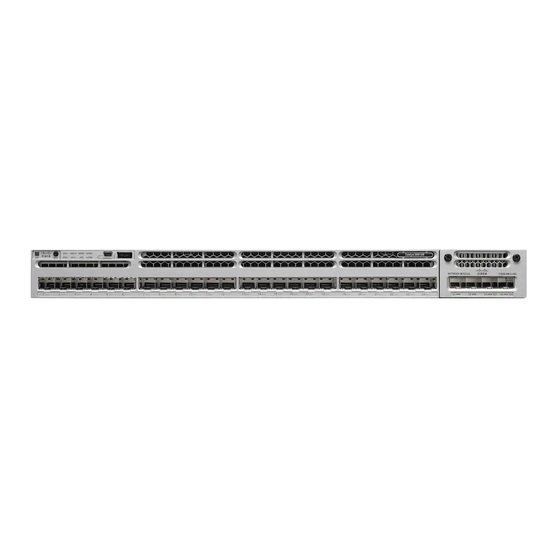
Mode button All of the switches have similar components. See Figure 1-1 Figure 1-2 for examples. The Catalyst 3850 switches might have slight cosmetic differences on the bezels. Note Figure 1-1 Catalyst 3850-48P-L Switch Front Panel Mode button USB mini-Type B (console) port... -
Page 15: 10/100/1000 Ethernet Ports
IEEE 802.3at-compliant powered devices (up to 30 W PoE+ per port). The maximum total PoE power in a 1RU switch is 1800 W. Cisco UPOE ports: Support for powered devices on all four Ethernet signal pairs (up to 60 W Cisco •... -
Page 16: Management Ports
Product Overview Front Panel Depending on the installed power supply modules, each port can deliver up to 60 W of Cisco UPOE. See Table 1-15 on page 1-19 for the power supply matrix that defines the available PoE, PoE+, and Cisco UPOE power per port. -
Page 17: Usb Type A Port
The interface supports Cisco USB flash drives with capacities from 64 MB to 1 GB. Cisco IOS software provides standard file system access to the flash device: read, write, erase, and copy, as well as the ability to format the flash device with a FAT file system. -
Page 18: Sfp And Sfp+ Modules
SFP module slot. The SFP modules have LC connectors for fiber-optic connections or RJ-45 connectors for copper connections. Use only Cisco SFP and SFP+ modules on the switch. For the latest information about supported SFP and SFP+ modules, refer to the Cisco Transceiver Modules Compatibility Information at: http://www.cisco.com/en/US/products/hw/modules/ps5455/products_device_support_tables_list.html... -
Page 19: Leds
(Expandable power system) 10 S-PWR (StackPower) 1. The XPS 2200 is not supported in this release. 2. Only switches with PoE+ ports. The Catalyst 3850 switches might have slight cosmetic differences on the bezels. Note Catalyst 3850 Switch Hardware Installation Guide OL-26779-02... -
Page 20: Syst Led
The power supply in a switch has failed, and the XPS is providing power to that switch (redundancy has been allocated to this device). For information about the XPS 2200, see the Cisco eXpandable Power System 2200 Hardware Installation Guide on Cisco.com: http://www.cisco.com/go/xps2200_hw... -
Page 21: Port Leds And Modes
Port is blocked by Spanning Tree Protocol (STP) and is not forwarding data. After a port is reconfigured, the port LED can be amber for up to 30 seconds as STP checks the switch for possible loops. Catalyst 3850 Switch Hardware Installation Guide 1-11 OL-26779-02... - Page 22 Blinking green Switch is a standby member of a data stack and assumes active responsibilities if the current active switch fails. STACK No stack member corresponding to that member number. (stack member) Blinking green Stack member number. Green Member numbers of other stack member switches. Catalyst 3850 Switch Hardware Installation Guide 1-12 OL-26779-02...
-
Page 23: Usb Console Led
USB console is enabled. S-PWR LED Table 1-8 S-PWR LED Color Description StackPower cable is not connected, or the switch is in standalone mode. Green Each StackPower port is connected to another switch. Catalyst 3850 Switch Hardware Installation Guide 1-13 OL-26779-02... -
Page 24: Actv Led
Stack, the LED for port 1 blinks green. The LEDs for ports 2 and 3 are solid green, as these represent the member numbers of other switches in the stack. The other port LEDs are off because there are no more members in the stack. Catalyst 3850 Switch Hardware Installation Guide 1-14 OL-26779-02... -
Page 25: Poe Led
When you select the STACK LED mode, the representative STACK LEDs are green when the StackWise ports are up, and the representative STACK LEDs are amber when the ports are down. PoE LED The PoE LED indicates the status of the PoE mode: either PoE, PoE+, or Cisco UPOE. Table 1-10 PoE LED Status... -
Page 26: Network Module Leds
Link faults occur when noncompliant cabling is Caution connected to an SFP or SFP+ port. Use only standard-compliant cabling to connect to Cisco SFP and SFP+ ports. You must remove from the network any cable or device that causes a link fault. -
Page 27: Rear Panel
RJ-45 Console Port LED Table 1-12 RJ-45 Console Port LED Color RJ-45 Console Port Status RJ-45 console is disabled. USB console is active. Green RJ-45 console is enabled. USB console is disabled. Catalyst 3850 Switch Hardware Installation Guide 1-17 OL-26779-02... -
Page 28: Stackwise Ports
The switch can operate with either one or two active power supply modules or with power supplied by a stack. A Catalyst 3850 switch that is in a StackPower stack can operate with power supplied by other switches in the stack. - Page 29 660 W 48-port Cisco UPOE 185 W switch 625 W Table 1-15 Switch Power Supply Requirements for PoE, PoE+, and Cisco UPOE PoE Option 24-Port Switch 48-Port Switch PoE (up to 15.4 per (1) 715-W These are the combinations of power...
- Page 30 Chapter 1 Product Overview Rear Panel Table 1-15 Switch Power Supply Requirements for PoE, PoE+, and Cisco UPOE (continued) PoE Option 24-Port Switch 48-Port Switch PoE+ (up to 30 W per These are the combinations of These are the combinations of power...
-
Page 31: Fan Modules
The switch can operate with two operational fans, but the failed fan should be replaced as soon as possible to avoid a service interruption due to a second fan fault. Three fans are required for proper cooling. Note Catalyst 3850 Switch Hardware Installation Guide 1-21 OL-26779-02... -
Page 32: Stackpower Connector
Appendix A, “Technical Specifications.” StackPower Connector The Catalyst 3850 switches have a StackPower connector for use with Cisco StackPower cables to configure a switch power stack that includes up to four switches. A switch power stack can be configured in redundant or power-sharing mode. -
Page 33: Management Ports
Cisco Network Assistant • Cisco Network Assistant is a PC-based network management GUI application for LANs. You can use the GUI to configure and manage switch clusters or standalone switches. Cisco Network Assistant is available at no cost and can be downloaded from this URL: http://www.cisco.com/pcgi-bin/tablebuild.pl/NetworkAssistant... -
Page 34: Network Configurations
• Cisco Prime Infrastructure combines the wireless functionality of Cisco Prime Network Control System (NCS) and the wired functionality of Cisco Prime LAN Management Solution (LMS), with application performance monitoring and troubleshooting capabilities of Cisco Prime Assurance Manager. For more information, see the Cisco Prime Infrastructure documentation on Cisco.com. -
Page 35: Switch Installation
C H A P T E R Switch Installation This chapter describes how to install and connect a Catalyst 3850 switch. It also includes planning and cabling considerations for stacking switches. Read the topics and perform the procedures in this order: Preparing for Installation, page 2-1 •... -
Page 36: Preparing For Installation
VoIP and the emergency calling service. In the USA, this emergency number is 911. You need to be aware of the emergency number in your country. Statement 361 Warning If a Cisco external power system is not connected to the switch, install the provided connector cover on the back of the switch. Statement 386 Warning Do not work on the system or connect or disconnect cables during periods of lightning activity. -
Page 37: Installation Guidelines
Cabling is away from sources of electrical noise, such as radios, power lines, and fluorescent • lighting fixtures. Make sure that the cabling is safely away from other devices that might damage the cables. Catalyst 3850 Switch Hardware Installation Guide OL-26779-02... -
Page 38: Tools And Equipment
• multirack assembly, the temperature around it might be greater than normal room temperature. Cisco Ethernet switches are equipped with cooling mechanisms, such as fans and blowers. However, • these fans and blowers can draw dust and other particles, causing contaminant buildup inside the chassis, which can result in system malfunction. -
Page 39: Switch Stacking And Power Stacking Guidelines
If you do not specify the length of the StackWise cable, the 0.5-meter cable is supplied. If you need the 1-meter cable or the 3-meter cable, you can order it from your Cisco supplier. For cable part numbers, see the “StackWise Ports”... -
Page 40: Data Stack Bandwidth And Partitioning Examples
Data Stack Bandwidth and Partitioning Examples This section provides examples of data stack bandwidth and possible data stack partitioning. Figure 2-3 shows a data stack of Catalyst 3850 switches that provides full bandwidth and redundant StackWise cable connections. Figure 2-3... -
Page 41: Power-On Sequence For Switch Data Stacks
Data Stack Cabling Configurations Figure 2-5 Figure 2-6 show data stacks of Catalyst 3850 switches with failover conditions. In Figure 2-5, the StackWise cable is bad in link 2. Therefore, this stack provides only half bandwidth and does not have redundant connections. In Figure 2-6, link 2 is bad. -
Page 42: Planning A Stackpower Stack
For conditions that can cause a stack reelection or to manually elect the active switch, see the stacking software configuration guide on Cisco.com at this URL: http://www.cisco.com/go/cat3850_docs Planning a StackPower Stack Catalyst 3850 switches can share power by using the StackPower feature. StackPower Stacking Guidelines, page 2-8 • StackPower Cabling Configurations, page 2-9 •... -
Page 43: Stackpower Cabling Configurations
If you do not specify the length of the StackPower cable, the 0.3 meter cable is supplied. If you need the 1.5 meter cable, you can order it from your Cisco supplier. For cable part numbers, see “StackPower Connector” section on page 1-22. - Page 44 S-P WR S -P W R P S O K A C O K RE SE T MG MT CO NS OL S -P W R X P S S -P W R Catalyst 3850 Switch Hardware Installation Guide 2-10 OL-26779-02...
-
Page 45: Stackpower Partitioning Examples
• After Installing the Switch, page 2-16 • The illustrations shown in this section show the Catalyst 3850-48 PoE+ switch as an example. You can install other Catalyst 3850 switches following the same procedures. Catalyst 3850 Switch Hardware Installation Guide... -
Page 46: Rack-Mounting
The 19-inch brackets are included with the switch. Installing the switch in other rack types requires an optional bracket kit not included with the switch. Figure 2-11 shows the mounting brackets and part numbers. Catalyst 3850 Switch Hardware Installation Guide 2-12 OL-26779-02... -
Page 47: Attaching The Rack-Mount Brackets
To install the switch in a rack, use four Phillips flat-head screws to attach the long side of the brackets to the switch for the front- or rear-mounting positions (Figure 2-12). Use four screws to attach the brackets for the front-mounting position. Catalyst 3850 Switch Hardware Installation Guide 2-13 OL-26779-02... - Page 48 Chapter 2 Switch Installation Installing the Switch Figure 2-12 Attaching Brackets for 19-inch Racks Rear-mounting position Number-8 Phillips flat-head screws Front-mounting position Catalyst 3850 Switch Hardware Installation Guide 2-14 OL-26779-02...
-
Page 49: Mounting The Switch In A Rack
“After Installing the Switch” section on page 2-16 for more information switch configuration. Figure 2-13 Mounting the Switch in a Rack Phillips machine screw, black Front-mounting position Cable guide Number-12 or number-10 Phillips machine screws Catalyst 3850 Switch Hardware Installation Guide 2-15 OL-26779-02... -
Page 50: Table- Or Shelf-Mounting
Configure the switch by running Express Setup to enter the initial switch configuration. For • instructions, see the switch getting started guide that shipped with the switch and also on Cisco.com. • Use the CLI setup program to enter the initial switch configuration. See Appendix C, “Configuring... -
Page 51: Connecting To The Stackwise Ports
Connect the cable to the StackWise port on the switch rear panel. Align the connector and connect the Step 2 StackWise cable to the StackWise port on the switch rear panel and finger-tighten the screws (clockwise direction). Make sure the Cisco logo is on the top side of the connector as shown in Figure 2-15. -
Page 52: Connecting To The Stackpower Ports
StackPower port on the switch rear panel. (Figure 2-16). Connect the end of the cable with the yellow band to another Catalyst 3850 switch (to configure Step 3 StackPower power sharing). Hand-tighten the captive screws to secure the StackPower cable connectors in place. -
Page 53: Installing A Network Module In The Switch
10/100/1000 Ethernet port regardless of the type of device on the other end of the connection. See the switch software configuration guide or the switch command reference on Cisco.com for more information about enabling or disabling autonegotiation and auto-MDIX. -
Page 54: Poe+ And Cisco Upoe Port Connections
PoE inline power supports devices compliant with the IEEE 802.3af standard, as well as prestandard Cisco IP Phones and Cisco Aironet Access Points. Each port can deliver up to 15.4 W of PoE. PoE+ inline power supports devices compliant with the IEEE 802.3at standard, by delivering up to 30 W of PoE+ power per port to all switch ports. -
Page 55: Where To Go Next
Use the CLI to configure the switch as a member of a cluster or as an individual switch from the • console. See the switch command reference on Cisco.com for information on using the CLI with the switch. Use the Cisco Prime Infrastructure application. - Page 56 Chapter 2 Switch Installation Where to Go Next Catalyst 3850 Switch Hardware Installation Guide 2-22 OL-26779-02...
- Page 57 Slots 1, 2, 3, and 4 populated with 1-Gigabit SFP modules. • Slots 1 and 2 populated with 1-Gigabit SFP modules, and Slot 4 populated with one 10-Gigabit SFP+ module. • Slots 3 and 4 each populated with 10-Gigabit SFP+ modules. Catalyst 3850 Switch Hardware Installation Guide OL-26779-02...
-
Page 58: Installing A Network Module
1. All network modules are hot-swappable. Figure 3-1 C3850-NM-4-1G Network Module Captive screws LEDs 1-Gigabit Ethernet ports Figure 3-2 C3850-NM-2-10G Network Module Captive screws 1-Gigabit Ethernet SFP slots 1-Gigabit or 10-Gigabit Ethernet SFP+ slots LEDs Catalyst 3850 Switch Hardware Installation Guide OL-26779-02... - Page 59 Chapter 3 Installing a Network Module Overview Figure 3-3 C3850-NM-4-10G Network Module Captive screws LEDs 10-Gigabit slots or 1-Gigabit Ethernet SFP slots Figure 3-4 Blank Network Module Blank module Captive screws Catalyst 3850 Switch Hardware Installation Guide OL-26779-02...
-
Page 60: Network Module Leds
Safety Warnings This section includes the installation cautions and warnings. Translations of the safety warnings appear in the Regulatory Compliance and Safety Information for the Catalyst 3850 Switches on Cisco.com: http://www.cisco.com/go/cat3850_hw Read this section before you install a network module. -
Page 61: Tools And Equipment
Step 1 Attach an ESD-preventive wrist strap to your wrist and to an earth ground surface. Step 2 Remove the module from the protective packaging. Catalyst 3850 Switch Hardware Installation Guide OL-26779-02... - Page 62 Position the module face up to install it in the module slot. Slide the module into the slot until the back Step 4 of the module faceplate is flush with the switch faceplate. Fasten the captive screws to secure the network module in place. Figure 3-5 Installing the Network Module in the Switch Catalyst 3850 Switch Hardware Installation Guide OL-26779-02...
-
Page 63: Configuring A Network Module
CLI. Interface Action GigabitEthernet1/1/1 Disregard GigabitEthernet1/1/2 Disregard GigabitEthernet1/1/3 Disregard GigabitEthernet1/1/4 Disregard TenGigabitEthernet1/1/1 Configure this interface TenGigabitEthernet1/1/2 Configure this interface TenGigabitEthernet1/1/3 Configure this interface TenGigabitEthernet1/1/4 Configure this interface Catalyst 3850 Switch Hardware Installation Guide OL-26779-02... -
Page 64: C3850-Nm-2-10G Module
GLC-SX-MMD • SFP-10G-LRM • GLC-LH-SMD SFP-10G-LR GLC-ZX-SM • • SFP-10G-ER GLC-ZX-SMD • • GLC-BX-D • GLC-BX-U • CWDM SFP • SFP-GE-S • SFP-GE-L • SFP-GE-Z • DWDM SFP • DWDM SFP (add.) • Catalyst 3850 Switch Hardware Installation Guide OL-26779-02... -
Page 65: Removing A Network Module
You must have an installed network module to use SFP and SFP+ modules. See the “SFP and SFP+ Modules” section on page 1-8, and the switch release notes on Cisco.com for the list of supported SFP and SFP+ modules. Use only supported SFP modules on the switch. See the following compatibility matrices: 10-Gigabit Ethernet Transceiver Modules Compatibility Matrix •... - Page 66 Step 5 If the module has a bale-clasp latch, close it to lock the SFP module in place. Step 6 Remove the SFP dust plugs and save. Step 7 Connect the SFP cables. Catalyst 3850 Switch Hardware Installation Guide 3-10 OL-26779-02...
-
Page 67: Removing Sfp Or Sfp+ Modules
Place the SFP module in an antistatic bag or other protective environment. Finding the Network Module Serial Number If you contact Cisco Technical Assistance regarding a network module, you need to know its serial number. Catalyst 3850 Switch Hardware Installation Guide... - Page 68 Chapter 3 Installing a Network Module Finding the Network Module Serial Number Figure 3-8 Network Module Serial Number Location SN: XXXNNNNXXXX Catalyst 3850 Switch Hardware Installation Guide 3-12 OL-26779-02...
- Page 69 Finding the Power Supply Module Serial Number, page 4-12 Power Supply Module Overview The switch operates with either one or two active power supply modules. A Catalyst 3850 switch that is part of a StackPower stack operates with power supplied by other stack switches.
-
Page 70: Power Supply Installation
AC O K PS O K PW R- C1 -1 10 0W 1100-W AC power supply module Release latch AC OK LED Power cord retainer PS OK LED Keying feature AC power cord connector Catalyst 3850 Switch Hardware Installation Guide OL-26779-02... -
Page 71: Chapter 4 Power Supply Installation
AC O K PS O K PW R- C1 -3 50 W AC 350-W AC power supply module Release latch AC OK LED Power cord retainer PS OK LED Keying feature AC power cord connector Catalyst 3850 Switch Hardware Installation Guide OL-26779-02... - Page 72 If no power supply is installed in a power supply slot, install a power supply slot cover (Figure 4-5). Figure 4-5 Power Supply Slot Cover Release handles Retainer clips The power supply modules have two status LEDs. Catalyst 3850 Switch Hardware Installation Guide OL-26779-02...
-
Page 73: Installation Guidelines
Do not operate the system unless all cards, faceplates, front covers, and rear covers are in place. Statement 1029 Catalyst 3850 Switch Hardware Installation Guide OL-26779-02... -
Page 74: Installing Or Replacing An Ac Power Supply
Only trained and qualified personnel should be allowed to install, replace, or service this equipment. Warning Statement 1030 If a Cisco external power system is not connected to the switch, install the provided connector cover Warning on the back of the switch. Statement 386 Installing or Replacing an AC Power Supply Turn off the power at its source. -
Page 75: Installing A Dc Power Supply
An exposed wire lead from a DC-input power source can conduct harmful levels of electricity. Be sure that no exposed portion of the DC-input power source wire extends from the terminal block plug. Statement 122 Catalyst 3850 Switch Hardware Installation Guide OL-26779-02... -
Page 76: Equipment That You Need
This equipment must be grounded. Never defeat the ground conductor or operate the equipment in the absence of a suitably installed ground conductor. Contact the appropriate electrical inspection authority or an electrician if you are uncertain that suitable grounding is available. Statement 1024 Catalyst 3850 Switch Hardware Installation Guide OL-26779-02... - Page 77 Using a ratcheting torque screwdriver, torque the ground-lug screws to 60 lbf-in. (960 ozf-in.). Step 6 Step 7 Connect the other end of the grounding wire to an appropriate grounding point at your site or to the rack. Catalyst 3850 Switch Hardware Installation Guide OL-26779-02...
- Page 78 Chapter 4 Power Supply Installation Installing a DC Power Supply Figure 4-10 Attaching the Ground Lug and Wire Assembly Single-ground screw and lug ring Dual-ground adapter and dual-hole lug Catalyst 3850 Switch Hardware Installation Guide 4-10 OL-26779-02...
-
Page 79: Installing The Dc Power Supply In The Switch
Use copper conductors only. Statement 1025 Warning Using a Panduit crimping tool, crimp the fork-type terminals to the copper conductor, 90C, 14-AWG DC Step 2 power input wires. Catalyst 3850 Switch Hardware Installation Guide 4-11 OL-26779-02... -
Page 80: Finding The Power Supply Module Serial Number
Step 7 the module LEDs. Finding the Power Supply Module Serial Number If you contact Cisco Technical Assistance regarding a power supply module, you need to know the serial number. See Figure 4-14 Figure 4-16 to find the serial number. You can also use the CLI to find out the serial number. - Page 81 Finding the Power Supply Module Serial Number Figure 4-14 1100-W AC Power Supply Serial Number SN: XXXNNNNXXXX Figure 4-15 715-W and 350-W AC Power Supply Module Serial Number SN: XXXNNNNXXXX R -C 1 -7 1 5 W A Catalyst 3850 Switch Hardware Installation Guide 4-13 OL-26779-02...
- Page 82 Chapter 4 Power Supply Installation Finding the Power Supply Module Serial Number Figure 4-16 440-W DC Power Supply Module Serial Number SN: XXXNNNNXXXX R -C 1 -4 4 Catalyst 3850 Switch Hardware Installation Guide 4-14 OL-26779-02...
-
Page 83: Installing The Fan
The switch can operate with two operational fans and one nonfunctional fan, but the failed fan should be replaced as soon as possible to avoid a service interruption due to a second fan fault. Three fans are required for proper cooling. Note Catalyst 3850 Switch Hardware Installation Guide OL-26779-02... -
Page 84: Chapter 5 Installing The Fan
Statement 1030 Installing a Fan Module Pinch the fan module release handle, and slide the module out. Step 1 You should replace the fan module within 5 minutes to avoid overheating the switch. Caution Catalyst 3850 Switch Hardware Installation Guide OL-26779-02... -
Page 85: Finding The Fan Module Serial Number
Figure 5-2 Installing the Fan Module Fan LED Finding the Fan Module Serial Number If you contact Cisco Technical Assistance regarding a fan module, you need to know the fan module serial number. See Figure 5-3 for the serial number location. - Page 86 Chapter 5 Installing the Fan Finding the Fan Module Serial Number Figure 5-3 Fan Module Serial Number SN: XXXNNNNXXXX Catalyst 3850 Switch Hardware Installation Guide OL-26779-02...
-
Page 87: Chapter 6 Troubleshooting
SYSTEM LED turns solid green, the ACTV LED is green if the switch is acting as the active switch. POST failures are usually fatal. Contact your Cisco technical support representative if your switch does Note not pass POST. -
Page 88: Switch Connections
Try the cable in another port to see if the problem follows the cable. • For Catalyst 3850 switch StackWise cable, remove and inspect the cable and StackWise port for bent • pins or damaged connectors. If the StackWise cable is bad, replace it with a known good cable. -
Page 89: 10/100/1000 Port Connections
Inspect the network module and SFP module. Exchange the suspect module with a known good • module. Verify that the module is supported on this platform. (The switch release notes on Cisco.com list the • SFP and SFP+ modules that the switch supports.) •... -
Page 90: Interface Settings
You can enable UniDirectional Link Detection (UDLD) on the switch to help identify unidirectional link problems. For information about enabling UDLD on the switch, see the “Understanding UDLD” section in the software configuration guide on Cisco.com. Switch Performance Speed, Duplex, and Autonegotiation Port statistics that show a large amount of alignment errors, frame check sequence (FCS), or late-collisions errors, might mean a speed or duplex mismatch. -
Page 91: Autonegotiation And Network Interface Cards
Alternatively, you can press the Reset button on the rear of the switch (approximately 5 seconds) to power cycle the switch. You can also configure the switch by using the CLI setup procedure. See Appendix C, “Configuring the Switch with the CLI-Based Setup Program.” Catalyst 3850 Switch Hardware Installation Guide OL-26779-02... -
Page 92: Finding The Switch Serial Number
Troubleshooting Finding the Switch Serial Number Finding the Switch Serial Number If you contact Cisco Technical Assistance, you need to know the switch serial number. Figure 6-1 shows the serial number location. You can also use the show version privileged EXEC command to see the switch serial number. -
Page 93: Appendix
(weights do not include the network modules, power supplies, or blanks). Catalyst 3850 24-port PoE switches 13.3 lb (6.0 kg) Catalyst 3850 24-port non PoE switches 13.1 lbs (6.0 kg) Catalyst 3850 48-port non PoE switches 14.2 lbs (6.5 kg) Catalyst 3850 48-port PoE switches 14.4 lbs (6.5) - Page 94 PWR-C1-1100WAC: 1100-W, 115 to 240 VAC (autoranging) 50 to 60 Hz PWR-C1-715WAC: 715 W, PWR-C1-350WAC: 350 W, 100 to 240 VAC (autoranging), 50 to 60 Hz Input current PWR-C1-1100WAC:12–6 A PWR-C1-715WAC: 10–5 A PWR-C1-350WAC: 4–2 A Catalyst 3850 Switch Hardware Installation Guide OL-26779-02...
-
Page 95: Appendix A Technical Specification
PWR-C1-440WDC: 20 A 1. The total input and total output BTU ratings refer to input power to the power supply and output power to the switch. The BTU ratings are based on –36 VDC. Catalyst 3850 Switch Hardware Installation Guide OL-26779-02... -
Page 96: Fan Module Specifications
Up to 13,000 ft (4,000 m) Physical Specification Dimensions (H x D x W) 1.62 x 1.73 x 4.24 in. (4.11 x 4.39 x 10.76 cm) Weight 0.2 lb (0.07 kg) Operating Specification Airflow 20 cfm Catalyst 3850 Switch Hardware Installation Guide OL-26779-02... -
Page 97: Appendix
10/100/1000 Ports The 10/100/1000 Ethernet ports on switches use RJ-45 connectors and Ethernet pinouts. Figure B-1 10/100/1000 Port Pinouts Label 4 5 6 7 8 TP0+ TP0- TP1+ TP2+ TP2- TP1- TP3+ TP3- Catalyst 3850 Switch Hardware Installation Guide OL-26779-02... -
Page 98: Connector Specifications
The switch supports the SFP module patch cable, a 0.5-meter, copper, passive cable with SFP module connectors at each end (Figure B-6). This cable can be used (only with 1-Gigabit Ethernet SFP ports) to connect two Catalyst 3850 switches in a cascaded configuration. Figure B-3 Duplex LC Cable Connector Catalyst 3850 Switch Hardware Installation Guide... -
Page 99: 10/100/1000 Ethernet Management Port
TP0- TP1+ TP2+ TP2- TP1- TP3+ TP3- Figure B-6 SFP Module Patch Cable 10/100/1000 Ethernet Management Port The 10/100/1000 Ethernet management port uses RJ-45 connectors with Ethernet pinouts. Figure B-7 shows the pinouts. Catalyst 3850 Switch Hardware Installation Guide OL-26779-02... -
Page 100: Console Port
B-9. The USB Type A-to-USB mini-Type B cable is not supplied. You can order an accessory kit (part number 800-33434) that contains this cable. Figure B-9 USB Type A-to-USB 5-Pin Mini-Type B Cable Catalyst 3850 Switch Hardware Installation Guide OL-26779-02... -
Page 101: Cable And Adapter Specifications
• Identifying a Crossover Cable, page B-7 • Console Port Adapter Pinouts, page B-7 StackWise Cables You can order these Catalyst 3850 to Catalyst 3850 StackWise cables (nonhalogen) from your Cisco sales representative: • STACK-T1-50CM= (0.5-meter cable) • STACK-T1-1M= (1-meter cable) STACK-T1-3M= (3-meter cable) •... -
Page 102: Four Twisted-Pair Cable Pinouts
8 TP3- Two Twisted-Pair Cable Pinouts Figure B-12 Two Twisted-Pair Straight-Through Cable Schematic Switch Router or PC 3 TD+ 3 RD+ 6 TD– 6 RD– 1 RD+ 1 TD+ 2 RD– 2 TD– Catalyst 3850 Switch Hardware Installation Guide OL-26779-02... -
Page 103: Identifying A Crossover Cable
RF-45-to-DB-9 adapter cable, and the console device. Table B-1 Console Port Signaling Using a DB-9 Adapter Switch Console RJ-45-to-DB-9 Console Port (DTE) Terminal Adapter Device Signal DB-9 Pin Signal Catalyst 3850 Switch Hardware Installation Guide OL-26779-02... - Page 104 Appendix B Connector and Cable Specifications Cable and Adapter Specifications Table B-1 Console Port Signaling Using a DB-9 Adapter (continued) Switch Console RJ-45-to-DB-9 Console Port (DTE) Terminal Adapter Device Signal DB-9 Pin Signal Catalyst 3850 Switch Hardware Installation Guide OL-26779-02...
- Page 105 The RJ-45-to-DB-25 female DTE adapter is not supplied with the switch. You can order a kit with the Note adapter (part number ACS-DSBUASYN=) from Cisco. Table B-2 Console Port Signaling Using a DB-25 Adapter Switch Console RJ-45-to-DB-25 Console Port (DTE) Terminal Adapter Device Signal DB-25 Pin Signal Catalyst 3850 Switch Hardware Installation Guide OL-26779-02...
- Page 106 Appendix B Connector and Cable Specifications Cable and Adapter Specifications Catalyst 3850 Switch Hardware Installation Guide B-10 OL-26779-02...
-
Page 107: Appendix
This appendix provides a CLI-based setup procedure for a Catalyst 3850 standalone switch or a switch stack. To set up the switch by using Express Setup, see the Catalyst 3850 Switch Getting Started Guide. Before connecting the switch to a power source, review the safety warnings in Chapter 2, “Switch... -
Page 108: A P P E N D I X C Configuring The Switch With The Cli-Based Setup Program
Accessing the CLI Through a Console Port You can enter Cisco IOS commands and parameters through the CLI. If you have stacked Catalyst 3850 switches, connect to the 10/100/1000 Ethernet management port or Note console port of one of the stack switches. You can perform the initial configuration for the entire stack on any switch in the stack. - Page 109 Configuring the Switch with the CLI-Based Setup Program Accessing the CLI Figure C-1 Connecting the USB Console Cable to the Catalyst 3850 Switch Connect a USB cable to the PC USB port. Connect the other end of the cable to the switch mini-B Step 2 (5-pin-connector) USB console port.
-
Page 110: Usb Console Port
A USB device driver must be installed the first time a Microsoft Windows-based PC is connected to the USB console port on the switch. Obtain the Cisco USB console driver file from the Cisco.com web site and unzip it. Step 1 You can download the driver file from the Cisco.com site for downloading the switch software. -
Page 111: Entering The Initial Configuration Information
Step 4 When the InstallShield Wizard Completed window appears, click Finish. Step 5 Uninstalling the Cisco Microsoft Windows Vista and Windows 7 USB Driver Disconnect the switch console terminal before uninstalling the driver. Note Run setup.exe for Windows 32-bit or setup(x64).exe for Windows-64bit. Click Next. - Page 112 Step 8 (Optional) Configure Simple Network Management Protocol (SNMP) by responding to the prompts. You can also configure SNMP later through the CLI, or the Cisco Network Assistant application. To configure SNMP later, enter no. Configure SNMP Network Management? [no]: no...
- Page 113 After you complete the setup program, the switch can run the default configuration that you created. To change this configuration or to perform other management tasks, enter commands at the prompt Switch> or use Cisco Network Assistant, or another management tool for further configuration. Catalyst 3850 Switch Hardware Installation Guide OL-26779-02...
- Page 114 Appendix C Configuring the Switch with the CLI-Based Setup Program Entering the Initial Configuration Information Catalyst 3850 Switch Hardware Installation Guide OL-26779-02...