Table of Contents
Advertisement
Available languages
Available languages
Oper
Opera a a a a tor
Oper
Oper
Oper
FAILURE TO READ AND FOLLOW ALL INSTRUCTIONS CAREFULLY
FAILURE TO READ AND FOLLOW ALL INSTRUCTIONS CAREFULLY
FAILURE TO READ AND FOLLOW ALL INSTRUCTIONS CAREFULLY
FAILURE TO READ AND FOLLOW ALL INSTRUCTIONS CAREFULLY
FAILURE TO READ AND FOLLOW ALL INSTRUCTIONS CAREFULLY
BEFORE INSTALLING OR OPERATING THIS CONTROL COULD CAUSE
BEFORE INSTALLING OR OPERATING THIS CONTROL COULD CAUSE
BEFORE INSTALLING OR OPERATING THIS CONTROL COULD CAUSE
BEFORE INSTALLING OR OPERATING THIS CONTROL COULD CAUSE
BEFORE INSTALLING OR OPERATING THIS CONTROL COULD CAUSE
PERSONAL INJURY AND/OR PROPERTY DAMAGE.
PERSONAL INJURY AND/OR PROPERTY DAMAGE.
PERSONAL INJURY AND/OR PROPERTY DAMAGE.
PERSONAL INJURY AND/OR PROPERTY DAMAGE.
PERSONAL INJURY AND/OR PROPERTY DAMAGE.
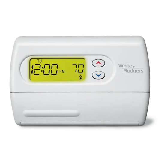
Your new White-Rodgers 5-Day/1-Day/1-Day Digital Thermo-
stat uses the technology of a solid-state microcomputer to
provide precise time/temperature control. This thermostat offers
you the flexibility to design heating and cooling programs that fit
your needs.
Features:
Features:
Features:
Features:
Features:
• Separate 5-day (weekday), 1-day (Sat) and 1-day (Sun) pro-
gramming with four separate time/temperature periods per day
• Simultaneous heat and cool program storage
• Preprogrammed temperature control
• Backlit display
• LCD continuously displays setpoint, and alternately dis-
plays time and room temperature
This thermostat is intended for use with a low voltage system; do
not use this thermostat with a line voltage system. If in doubt
about whether your wiring is millivolt, line, or low voltage, have
it inspected by a qualified heating and air conditioning contractor
or electrician.
Do not exceed the specification ratings.
All wiring must conform to local and national electrical codes and
ordinances.
This control is a precision instrument, and should be handled
carefully. Rough handling or distorting components could cause
the control to malfunction.
CAUTION
!
To prevent electrical shock and/or equipment damage,
To prevent electrical shock and/or equipment damage,
To prevent electrical shock and/or equipment damage,
To prevent electrical shock and/or equipment damage,
To prevent electrical shock and/or equipment damage,
disconnect electric power to system at main fuse or
disconnect electric power to system at main fuse or
disconnect electric power to system at main fuse or
disconnect electric power to system at main fuse or
disconnect electric power to system at main fuse or
circuit breaker box until installation is complete.
circuit breaker box until installation is complete.
circuit breaker box until installation is complete.
circuit breaker box until installation is complete.
circuit breaker box until installation is complete.
ELECTRICAL DATA
ELECTRICAL DATA
ELECTRICAL DATA
ELECTRICAL DATA
ELECTRICAL DATA
Electrical Rating:
Electrical Rating:
Electrical Rating:
Electrical Rating:
Electrical Rating:
8 to 30 VAC 50/60 Hz. or D.C.
0.05 to 1.0 Amps (Load per terminal)
1.5 Amps Maximum Total Load
1.5 Amps Maximum Total Load
1.5 Amps Maximum Total Load (All terminals combined)
1.5 Amps Maximum Total Load
1.5 Amps Maximum Total Load
THERMAL DATA
THERMAL DATA
THERMAL DATA
THERMAL DATA
THERMAL DATA
Setpoint Temperature Range:
Setpoint Temperature Range:
Setpoint Temperature Range:
Setpoint Temperature Range:
Setpoint Temperature Range:
45°F to 90°F (7°C to 32°C)
Operating Ambient Temperature Range:
Operating Ambient Temperature Range:
Operating Ambient Temperature Range:
Operating Ambient Temperature Range:
Operating Ambient Temperature Range:
32°F to 105°F
Operating Humidity Range:
Operating Humidity Range:
Operating Humidity Range:
Operating Humidity Range:
Operating Humidity Range:
0 to 90% RH (non-condensing)
Shipping Temperature Range:
Shipping Temperature Range:
Shipping Temperature Range:
Shipping Temperature Range:
Shipping Temperature Range:
-4°F to 149°F
tor
tor: : : : : Sa
tor
Sa
Sa
Sav v v v v e these instr
e these instr
e these instr
tor
Sa
e these instructions f
e these instr
APPLICATIONS
APPLICATIONS
White-Rodgers is a division
of Emerson Electric Co.
www.white-rodgers.com
1F80-361
1F80-361
1F80-361
1F80-361
1F80-361
Programmable Electronic Digital Thermostat
INSTALLATION AND
INSTALLATION AND
INSTALLATION AND
INSTALLATION AND
INSTALLATION AND
OPERATION INSTRUCTIONS
OPERATION INSTRUCTIONS
OPERATION INSTRUCTIONS
OPERATION INSTRUCTIONS
OPERATION INSTRUCTIONS
uctions f
uctions f
or futur
or futur
e use!
e use!
uctions for futur
uctions f
or future use!
or futur
e use!
e use!
• Temperature override until next program period
• Manual program override (HOLD temperature)
• Temporary HOLD
• °F/°C convertibility
• Temperature range 45° to 90°F
• RC, RH, C, W, Y, G , O and B terminals
• Optional C terminal (Dual Power option)
• B and O terminals for single stage heat pumps (no auxiliary
heat) or damper operation
• Program storage in case of power loss
• 2 "AA" alkaline batteries included
WARNING
!
Do not use on circuits exceeding specified voltage.
Do not use on circuits exceeding specified voltage.
Do not use on circuits exceeding specified voltage.
Do not use on circuits exceeding specified voltage.
Do not use on circuits exceeding specified voltage.
Higher voltage will damage control and could cause
Higher voltage will damage control and could cause
Higher voltage will damage control and could cause
Higher voltage will damage control and could cause
Higher voltage will damage control and could cause
shock or fire hazard.
shock or fire hazard.
shock or fire hazard.
shock or fire hazard.
shock or fire hazard.
Do not short out terminals on gas valve or primary control
Do not short out terminals on gas valve or primary control
Do not short out terminals on gas valve or primary control
Do not short out terminals on gas valve or primary control
Do not short out terminals on gas valve or primary control
to test. Short or incorrect wiring will damage thermostat
to test. Short or incorrect wiring will damage thermostat
to test. Short or incorrect wiring will damage thermostat
to test. Short or incorrect wiring will damage thermostat
to test. Short or incorrect wiring will damage thermostat
and could cause personal injury and/or property dam-
and could cause personal injury and/or property dam-
and could cause personal injury and/or property dam-
and could cause personal injury and/or property dam-
and could cause personal injury and/or property dam-
age.
age.
age.
age.
age.
Thermostat installation and all components of the sys-
Thermostat installation and all components of the sys-
Thermostat installation and all components of the sys-
Thermostat installation and all components of the sys-
Thermostat installation and all components of the sys-
tem shall conform to Class II circuits per the NEC code.
tem shall conform to Class II circuits per the NEC code.
tem shall conform to Class II circuits per the NEC code.
tem shall conform to Class II circuits per the NEC code.
tem shall conform to Class II circuits per the NEC code.
APPLICATIONS
APPLICATIONS
APPLICATIONS
For use with:
• Standard heat/cool or heat only systems
• Electric heat systems
• Gas or oil fired systems
• Gas systems with intermittent ignition devices (I.I.D.)
and/or vent dampers
• Hydronic (hot water or steam) systems
• Single-stage heat pump systems (no auxiliary heat)
• Millivolt systems
DO NOT USE WITH:
DO NOT USE WITH:
DO NOT USE WITH:
DO NOT USE WITH:
DO NOT USE WITH:
• Multi-stage systems
• Systems exceeding 30 VAC and 1.5 amps
• 3-wire zoned hydronic heating systems
DESCRIPTION
DESCRIPTION
DESCRIPTION
DESCRIPTION
DESCRIPTION
PRECAUTIONS
PRECAUTIONS
PRECAUTIONS
PRECAUTIONS
PRECAUTIONS
SPECIFICATIONS
SPECIFICATIONS
SPECIFICATIONS
SPECIFICATIONS
SPECIFICATIONS
PART NO. 37-6621C
PART NO. 37-6621C
PART NO. 37-6621C
PART NO. 37-6621C
PART NO. 37-6621C
Replaces 37-6621B
0745
Advertisement
Table of Contents

Related Manuals for White Rodgers 1F80-361


Summary of Contents for White Rodgers 1F80-361
- Page 1 1F80-361 1F80-361 1F80-361 1F80-361 1F80-361 Programmable Electronic Digital Thermostat INSTALLATION AND INSTALLATION AND INSTALLATION AND INSTALLATION AND INSTALLATION AND OPERATION INSTRUCTIONS OPERATION INSTRUCTIONS OPERATION INSTRUCTIONS OPERATION INSTRUCTIONS OPERATION INSTRUCTIONS Oper Oper Opera a a a a tor tor: : : : : Sa...
-
Page 2: Installation
INSTALLATION INSTALLATION INSTALLATION INSTALLATION INSTALLATION REMOVE OLD THERMOSTAT REMOVE OLD THERMOSTAT REMOVE OLD THERMOSTAT REMOVE OLD THERMOSTAT REMOVE OLD THERMOSTAT Screw anchors 1. Shut off electricity at the main fuse box until installation is complete. Ensure that electrical power is disconnected. 2. -
Page 3: Wiring Diagrams
JUMPER THERMOSTAT WIRE C ‡ THERMOSTAT SYSTEM C ‡ SYSTEM Cooling Heating 24 VAC 120 VAC System Relay System Heating Neutral Relay System HEATING TRANSFORMER 24 VAC 120 VAC NOTE Neutral For 2-wire Heat only, attach to RH and W TRANSFORMER 24 VAC 120 VAC... -
Page 4: Thermostat Buttons/Switches/Display
OPERATION OPERATION OPERATION OPERATION OPERATION Before you begin programming your thermostat, you should be familiar with its features and with the display and the location and operation of the thermostat buttons. Your thermostat con- sists of two parts: the thermostat cover thermostat cover thermostat cover thermostat cover... -
Page 5: Programming Thermostat
Configuration Menu Step Press Button(s) Displayed (Factory Default) Press to select: COMMENTS HOLD 0 to 8 hrs (in Select temporary Hold time PRGM (0:00) 15 minute increments) and RUN Select FA or SL (Fast or Slow) heating cycle rate HOLD* (FA) Select display backlight OFF or ON HOLD*... -
Page 6: Planning Program
Enter Heating Program Enter Heating Program Enter Heating Program Enter Heating Program Enter Heating Program Planning Your Program Planning Your Program Planning Your Program Planning Your Program Planning Your Program 1. Move the SYSTEM switch to HEAT HEAT HEAT HEAT HEAT. -
Page 7: Troubleshooting
Enter Cooling Program Enter Cooling Program Enter Cooling Program Enter Cooling Program Enter Cooling Program CHECK YOUR PROGRAMMING CHECK YOUR PROGRAMMING CHECK YOUR PROGRAMMING CHECK YOUR PROGRAMMING CHECK YOUR PROGRAMMING Follow these steps to check your thermostat programming one CAUTION final time before beginning thermostat operation. - Page 8 TROUBLESHOOTING TROUBLESHOOTING TROUBLESHOOTING TROUBLESHOOTING TROUBLESHOOTING Symptom Symptom P P P P P ossib ossib ossib le Cause le Cause Corrective Action Corrective Action Symptom Symptom Symptom ossib ossible Cause le Cause le Cause Corrective Action Corrective Action Corrective Action Heat, Cool or Fan Runs Constantly. Heat, Cool or Fan Runs Constantly.
-
Page 9: Especificaciones
1F80-361 Termostato digital electrónico programable INSTRUCCIONES DE INSTALACIÓN Y OPERACIÓN Sr. operador: ¡Conserve estas instrucciones para consultarlas en cualquier momento! EL NO LEER Y SEGUIR CON CUIDADO TODAS LAS INSTRUCCIONES ANTES DE INSTALAR O UTILIZAR ESTE CONTROL PODRÍA CAUSAR LESIONES PERSONALES Y/O DAÑOS MATERIALES. -
Page 10: Instalación
INSTALACIÓN RETIRE EL TERMOSTATO VIEJO Anclajes plásticos Apague la electricidad en la caja de fusibles principal hasta que haya finalizado la instalación. Asegúrese de que la alimentación eléctrica esté desconectada. 2. Retire la cubierta delantera del termostato viejo. Con los cables aún conectados, retire la placa de la pared. Si el termostato viejo tiene una placa de montaje sobre pared, retire el termostato y la placa juntos. 3. Identifique cada uno de los cables conectados al termostato viejo usando las etiquetas incluidas con el nuevo termostato. 4. Desconecte los cables del termostato viejo de a uno a la vez. NO DEJE QUE LOS CABLES VUELVAN A INTRODUCIRSE EN LA PARED. -
Page 11: Sistema De Refrigeración
CABLE DE SISTEMA PUENTE C ‡ SISTEMA TERMOSTATO C á Vivo TERMOSTATO Sistema de Relé del Sistema de 24 VCA 120 VCA refrigeración ventilador calefacción Relé del Sistema de Neutro ventilador calefacción TRANSFORMADOR Vivo NOTA DE CALEFACCIÓN 24 VCA 120 VCA Para sólo calor con Neutro 2 cables, conectar a... -
Page 12: Operación
OPERACIÓN Antes de que comience a programar su termostato, debe familiarizarse con sus funciones y con la pantalla y la ubicación y funcionamiento de los diferentes botones. Su termostato consta de dos partes: la cubierta del termostato y la base. Para retirar la cubierta, tire suavemente de ella para separarla de la base. Para volver a colocarla, alinee la cubierta con la base y presione suavemente hasta que se enganche en la base. Los botones e interruptores del termostato Sube el ajuste de temperatura. Baja el ajuste de temperatura. Botón TIME (tiempo). Botón PRGM (programa). Botón RUN (ejecutar programa). Botón HOLD (mantener temperatura). Interruptor FAN (ventilador) (ON, AUTO). Interruptor SYSTEM (COOL, OFF, HEAT). Figura 8. Pantalla, botones e La pantalla interruptores del termostato Presione HOLD para pasar a la siguiente opción del menú o presione Indica el día de la semana. TIME para volver a la opción anterior. Para salir del menú y volver a la El icono de la llama ( ) aparece cuando el interruptor SYSTEM operación del programa, presione RUN. Si pasan quince minutos sin está en la posición HEAT. El icono del copo de nieve ( ) aparece presionar ningún botón, el termostato volverá al modo de funcionamiento... -
Page 13: Programación Del Termostato
Menú de configuración La pantalla muestra Presione el Presione OBSERVACIONES Paso (ajustado de fábrica) botón o botones para seleccionar: HOLD 0 a 8 horas PRGM Selecciona el tiempo de mantenimiento temporal (en incrementos de 15 minutos) (0:00) y RUN Selecciona FA o SL (rápida o lenta) para la velocidad HOLD* del ciclo de calefacción (FA) - Page 14 Planificación del programa Ingreso del programa de calefacción 1. Mueva el interruptor SYSTEM a HEAT. Observe las horas y temperaturas preprogramadas de fábrica que se indican en el ejemplo. Si este programa es adecuado a sus necesidades, 2. Presione PRGM una sola vez. Aparecerá “MO TU WE TH FR FR” simplemente presione el botón RUN para comenzar a ejecutar el (que indica programa semanal) en la pantalla. También aparecerá programa preestablecido de fábrica. la hora de inicio actualmente programada para el 1° período de calefacción y la temperatura actualmente programada (en forma Si desea modificar las horas y temperaturas preprogramadas, siga los intermitente). pasos indicados a continuación. Determine las horas y temperaturas para sus programas semanales y EJEMPLO: de fines de semana. Debe programar cuatro períodos para el programa semanal y cuatro para el programa de fin de semana. No obstante, La pantalla indicará que para el 1° período semanal, la hora de...
-
Page 15: Solución De Problemas
VERIFIQUE SU PROGRAMACIÓN Ingreso del programa de refrigeración ▲ Siga los pasos indicados a continuación para verificar la programación ¡PRE- ¡PRECAUCIÓN! del termostato por última vez antes de comenzar a utilizarlo. Si la temperatura externa está por debajo de los 50°F, 1. Mueva el interruptor SYSTEM a la posición HEAT. desconecte la alimentación al sistema de refrigeración 2. Presione PRGM para ver la hora y temperatura del 1° período de antes de programar el termostato. Si energiza el calefacción semanal. Cada vez que presione PRGM, aparecerá... - Page 16 SOLUCIÓN DE PROBLEMAS Síntoma Causa posible Acción correctiva El sistema no enfría 1. E l interruptor SYSTEM no está ajustado en COOL. Coloque el interruptor SYSTEM en COOL y baje la temperatura de referencia por debajo de la temperatura ambiente. 2. L a conexión al termostato o al sistema está suelta. Verifique que los cables del termostato y del sistema estén bien conectados. 3. E l sistema de refrigeración requiere servicio Siga el mismo procedimiento de diagnóstico que técnico o debe cambiarse el termostato. cuando el sistema no calienta pero coloque el termostato en COOL y coloque la temperatura de referencia por debajo de la temperatura ambiente. El termostato puede tardar hasta cinco minutos en pasar al modo de refrigeración si se ha seleccionado la opción de bloqueo del compresor en el menú de configuración (opción 6). El modo de calor, frío o ventilador 1. El interruptor FAN está en Fan ON.