Table of Contents
Advertisement
Quick Links
Advertisement
Table of Contents

Related Manuals for THOMSON TWG870


Summary of Contents for THOMSON TWG870
- Page 1 CABLE SATELLITE TELECOM TERRESTRIAL TWG870 - Wireless Voice Gateway User manual...
- Page 3 NORTH AMERICAN CABLE INSTALLER: This reminder is provided to call your attention to Article 820-40 of the National Electrical Code...
- Page 4 (Section 54 of the Canadian Electrical Code, Part 1) which provides guidelines for proper grounding and, in particular, specifies that the cable ground shall be connected to the grounding system of the building as close to the point of cable entry as practical. Euro-PacketCable and Euro-DOCSIS compliant This product was designed according to Euro-PacketCable Specifications, Euro-DOCSIS Specifications and Data over Cable Service Interface Specifications.
- Page 5 Front Panel The on/off button on the rear panel must be in the ON mode = on “1”...
- Page 7 To set the basic configuration for the wireless features, please click Radio item from the Wireless menu...
- Page 9 • High Speed Data Service Solution • EuroDOCSIS 3.0 cable modem, dual-mode (DOCSIS / EuroDOCSIS) • Giga Ethernet router with 4x Standard RJ-45 connectors for 10/100/1000Mbps. Auto-negotiation and MDIS functions • Wi-Fi 11n wireless connection • Wireless security: multiple SSID and WPS solution •...
- Page 10 • Electronic copy of this user’s guide in additional languages (PDF format) • Adobe Acrobat Reader — application you can load to read PDF format, if you don’t have it loaded already • Links to Thomson web site EuroDOCSIS and EuroPacketCable are trademarks of Euro Cable Television Laboratories, Inc.
- Page 11 For the best possible performance from your Wireless Voice Gateway, your personal computer must meet the following minimum system requirements (note that the minimum requirements may vary by cable companies): IBM PC COMPATIBLE MACINTOSH** Pentium preferred PowerPC or higher System RAM 16MB (32MB preferred) 24MB (32MB preferred) Operating System...
- Page 12 To do this: Ensure that the wall you use is smooth, flat, dry and sturdy and use the 2 screw holes which are 101.6 mm apart from each other. Fix the screws into wall, leaving their heads 3 mm (0.12 inch) clear of the wall surface. Remove any connections to the unit and locate it over the screw heads.
- Page 13 push the unit on to the wall and move it downwards to secure.
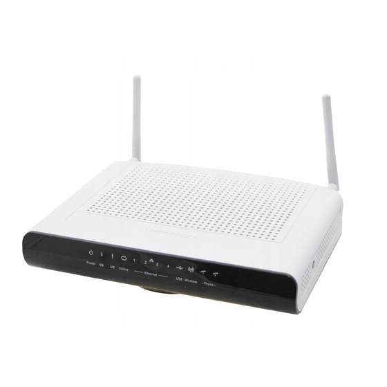
- Page 14 Front Panel The following illustration shows the front panel of the Wireless Voice Gateway: The LEDs on the front panel are described in the table below (from left to right):...
- Page 15 Wait registration with all DS and all US – Lights Flash sequentially from the right to left Minimum duration 3 seconds From 1 to 4 DS, from 1 to 4 LEDs are ON. From 5 to 8 DS, From 1 to 4 LEDs are flashing Duration 3 seconds From 1 to 2 US, from 1 to 2 LEDs are ON,...
- Page 16 TEL1 & TEL2 2x Telephony RJ-11 connectors ETHERNET 1 2 3 4: 4x Ethernet 10/100/1000 Mbps RJ-45 connectors USB Host: 1x USB 2.0 Connector Reset: 1x Reset or reset to factory default this Wireless Voice Gateway CABLE: 1x F-Connector for the coax cable 12VDC : 1x Power connector to connect the AC power supply Power switch:...
- Page 17 This illustration shows a cable company that offers Euro-DOCSIS- and Euro-PacketCable-compliant voice/data services. The Wireless Voice Gateway provides high-speed Internet access as well as cost-effective, toll-quality telephone voice and fax/modem services over residential, commercial, and education subscribers on public and private networks via an existing CATV infrastructure. It can inter-operate with the Euro-PacketCable compliant head-end equipment and provide the IP-based voice communications.
- Page 18 Make sure your local cable company provides data services that use cable TV industry-standard Euro-DOCSIS compliant and Euro-PacketCable compliant technology. Your cable company provides you access to an Internet Service Provider (ISP) and Telephony Service Provider (TSP). The ISP is your gateway to the Internet and provides you with a pipeline to access Internet content on the World Wide Web (WWW).
- Page 19 Note: It is important to supply power to the modem at all times. Keeping your modem plugged in will keep it connected to the Internet. This means that it will always be ready whenever you need. Important Information Your cable company should always be consulted before installing a new cable outlet. Do not attempt any rewiring without contacting your cable company first.
- Page 20 This section of the manual explains how to connect your Wireless Voice Gateway to the USB or Ethernet port on your computer and install the necessary software. Please refer to Figure 1 to help you connect your Digital Cable Modem for the best possible connection. ocate the Cable TV wire.
- Page 22 The Wireless Voice Gateway supports Ethernet and USB connections simultaneously. Below are important points to remember before you connect the Wireless Voice Gateway. For Ethernet connections, go to page 15. For telephone and fax connections, go to page 17. If you do not want to use the CD-ROM, follow instructions 1 through 5 to connect the Wireless Voice Gateway to the USB port on your computer.
- Page 23 Make the connection to the modem in the following sequence: 1. Connect one end of the coaxial cable to the cable connection on the wall, and the other end to the CABLE jack on the Wireless Voice Gateway. 2. Connect the plug from the AC power supply into the POWER AC ADAPTER jack on the Wireless Voice Gateway, and plug the power supply into an AC outlet.
- Page 24 If you need to connect more than one computer to the Wireless Voice Gateway, simply connect the computers to an Ethernet port on the rear panel. Note: You may need to check with your service provider in order to connect multiple computers. When properly connected, most telephony devices can be used with the Wireless Voice Gateway just as with a conventional telephone service.
- Page 25 dial tone, then dial the desired number. For services such as call waiting, use the hook switch (or FLASH button) to change calls. The following procedures describe some of the possible connection schemes for using telephony devices with the Wireless Voice Gateway. 1.
- Page 26 If there is no lighted LEDs on the front panel, check the power on/off switch position on the back panel of Wireless Gateway: it must be ”ON” = “1”. After installing the Wireless Voice Gateway and turn it on for the first time (and each time the modem is reconnected to the power), it goes through several steps before it can be used.
- Page 27 If both DS and US LEDs are flashing sequentially, it means the Wireless Voice Gateway is automatically updating its system software. Please wait for the lights to stop flashing. You cannot use your modem during this time. Do not remove the power supply, switch off (on/off switch) or reset the Wireless Voice Gateway during this process.
- Page 28 To make sure that you can access the Internet successfully, please check the following first. Make sure the connection (through Ethernet or USB) between the Wireless Voice Gateway and your computer is OK. Make sure the TCP/IP protocol is set properly. Subscribe to a Cable Company.
- Page 29 The main screen will be shown as below. Main Menu: the hyperlinks on the top of the page, including Gateway, VoIP and several sub-menu items Title: the sidebar on the left side of the page indicates the title of this management interface, e.g., Software in this example Main Window: the current workspace of the web management, containing configuration or status information...
- Page 30 At your first connection or while the password is the default one, a warning message is displayed on the top banner of each Web configuration page. We want to encourage you to change the password in order to enforce the security of your modem. Please refer to the chapter “ ”...
- Page 31 This page reports current connection status containing startup procedures, downstream and upstream status, CM online information, and so on. The information can be useful to your cable company’s support technician if you’re having problems.
-
Page 32: More Information
Forcing end user to change the password Upon access to the web pages on the CPE side of the router, if the user has not changed the default web password, a warning message must be displayed in the top banner of the web interface such as being visible while accessing any tabs. - Page 33 The password warning message is no more displayed on the banners once the default password has been replaced by a new one. At your first connection or while the password is the default one, a warning message is displayed on the top banner of each Web configuration page.
- Page 34 This page offers basic diagnostic tools for you to utilize when connectivity problems occur. When you ping an Internet device, you send a packet to its TCP/IP stack, and it sends one back to yours. To use the ping Test, enter the information needed and press Start Test; the Result will be displayed in the lower part of the window.
- Page 35 Fig. 11 This page displays the contents of the SNMP event log. Press “Clear Log” button to clear the logs.
- Page 36 Fig. 12 To speed up the modem’s first time startup, enter known downstream frequency and/or upstream channel ID information here. Then click “Apply and Reboot” button to start scanning the cable network beginning with the values supplied here. The value is provided in Hertz. So for 562 MHz, you must type: 562000000...
- Page 37 Fig. 13 Backup/Restore Settings : This page allows you to save your current settings locally on your PC, or restored settings previously saved.The file name is “GatewaySettings.bin”.
- Page 38 You can activate the DHCP server function for the LAN on this page. With this activated function, • your cable company’s DHCP server provides one IP address for your gateway, • and your gateway’s DHCP server provides IP addresses, starting at the address you set in IP Address on the LAN page, to your PCs.
- Page 39 Fig. 15 You can configure the optional internal DHCP server for the WAN on this page. This can be required by some ISP providers. Select different WAN Connection Type will lead to different contents. Take the WAN connection type-DHCP for example, you can release and renew the WAN lease by pressing the buttons. You can enter a spoofed MAC address that causes your gateway networking stack to use that MAC address when communicating instead of the usual WAN MAC address, e.g., if the MAC address is 00:11:e3:df:66:95, this spoofed MAC address could be 00:11:e3:df:66:97 or any desired MAC...
- Page 40 Fig. 16 This page displays the status of the DHCP clients and current system time. You can cancel an IP address lease by selecting it in the DHCP Client Lease Info list and then clicking the Force Available button. If you do so, you may have to perform a DHCP Renew on that PC, so that it can obtain a new lease.
- Page 41 This page allows to setup for Dynamic DNS server.
- Page 42 This page allows configuration and display of the system time obtained from network servers via Simple Network Time Protocol. The system has to be reset for any changes to take effect.
-
Page 43: Options
This page allows you to enable/disable some features of the Wireless Voice Gateway. Fig. 20 WAN Blocking prevents others on the WAN side from being able to ping your gateway. With WAN Blocking enabled, your gateway will not respond to pings it receives, effectively “hiding” your gateway. - Page 44 Multicast Enable enables multicast traffic to pass WAN LAN. You may need to enable this to see some types of broadcast streaming and content on the Internet. UPnP Universal Plug and Play (UPnP) helps devices, such as Internet appliances and computers, access the network and connect to other devices as needed.
- Page 45 Fig. 19 This page allows you to enter ranges of destination ports (applications) that you don’t want your LAN PCs to send packets to. Any packets your LAN PCs send to these destination ports will be blocked. For example, you could block access to worldwide web browsing (http = port 80) but still allow email service (SMTP port 25 and POP-3 port 110).
- Page 46 Fig. 20 For LAN WAN communications, the gateway normally only allows you to originate an IP connection with a PC on the WAN; it will ignore attempts of the WAN PC to originate a connection onto your PC. This protects you from malicious attacks from outsiders. However, sometimes you may wish for anyone outside to be able to originate a connection to a particular PC on your LAN if the destination port (application) matches one you specify.
- Page 47 Fig. 21 Some Internet activities, such as interactive gaming, require that a PC on the WAN side of your gateway be able to originate connections during the game with your game playing PC on the LAN side. You could use the Advanced-Forwarding web page to construct a forwarding rule during the game, and then remove it afterwards (to restore full protection to your LAN PC) to facilitate this.
- Page 48 Fig. 22 Port Triggering works as follows. Imagine you want to play a particular game with PCs somewhere on the Internet. You make one time effort to set up a Port Trigger for that game, by entering into Trigger Range the range of destination ports your game will be sending to, and entering into Target Range the range of destination ports the other player (on the WAN side) will be sending to (ports your PC’s game receives on).
- Page 49 Use this page to designate one PC on your LAN that should be left accessible to all PCs from the WAN side, for all ports. For example, if you put an HTTP server on this machine, anyone will be able to access that HTTP server by using your gateway IP address as the destination.
- Page 50 These pages allow you to enable, disable, and configure a variety of firewall features associated with web browsing, which uses the HTTP protocol and transports HTML web pages. On these pages, you designate the gateway packet types you want to have forwarded or blocked. You can activate settings by checking them and clicking Apply.
- Page 51 Use this page to set rules that will block specific LAN side PCs from accessing the Internet, but only at specific days and times. Specify a PC by its hardware MAC address, and then use the tools to specify blocking time. Finally, click the Apply button to save your settings. Fig.
- Page 52 The gateway builds a log of firewall blocking actions that Firewall has taken.Using the Local Log page lets you specify an email address to which you want the gateway to email this log. You must also tell the gateway your outgoing (i.e. SMTP) email server’s name, so it can direct the email to it. Enable Email Alerts has the gateway forward email notices when Firewall protection events occur.
- Page 53 Fig. 28 This page allows you to enable, disable, and configure a variety of firewall features associated with web browsing, which uses the HTTP protocol and transports HTML web pages. On these pages, you designate the gateway packet types you want to have forwarded or blocked. You can activate settings by checking them and clicking Apply.
- Page 54 The Wireless web pages group enables a variety of settings that can provide secure and reliable wireless communications for even the most demanding tech-savvy user. The Wireless Voice Gateway offers a choice of 802.1x, WPA and WPA-PSK authentication of your PCs to the gateway, 64 and 128 bit WEP encryption of communication between the gateway and your PCs to guaranty security, and an Access Control List function that enables you to restrict wireless access to only your specific PCs.
-
Page 55: Security
Security secures or scrambles messages traveling through the air between your wireless PCs and the gateway, so they can’t be observed by others. The following minimum security setting changes to factory defaults are recommended. See the 802.11b/g Security Web Page discussion below for details. Data Encryption –... - Page 56 Value List or Setting Description Default Range Network Set the Network Name Up to 32-character THOM-Dxxxxxxx Name (SSID) (also known as SSID) string containing of this network. ASCII characters with codes between 0x20 and 0x7e Network Select Closed to hide Open, Closed Open Type...
- Page 57 Fig. 31 It must be used in conjunction with an authentication server such as RADIUS to provide centralized access control and management. It can provide stronger encryption and authentication solution than none WPA modes. WPA2 is the second generation of WPA security WPA-PSK (WPA-Pre-Shared Key) /WPA2-PSK (WPA2-Pre-Shared Key): It is useful for small places without authentication servers such as the network at home.
- Page 58 You can choose 64-bit or 128-bit according to your needs. If you choose Disabled, the Network Keys will not be shown on this page. If selected, the data is encrypted using the key before being transmitted. For example, if you set 128-bit in this field, then the receiving station must be set to use the128 Bit Encryption, and have the same Key value too.
- Page 59 Earlier AP (RADIUS clients) use port 1945. The default value will be shown on this box. You can keep and use it. RADIUS Key: A RADIUS Key is like a password, which is used between IAS and the specific RADIUS client to verify identity. Both IAS and the RADIUS client must be use the same RADIUS Key for successful communication to occur.
- Page 60 RADIUS Server/RADIUS Port/RADIUS Key: Please refer to the previous page. Group Key Rotation Interval: Key in the time for the WAP group key rotation interval. The unit is second. With increasing rekey interval, user bandwidth requirement is reduced. WPA/WPA2 Re-auth Interval: When a wireless client has associated with the Wireless Voice Gateway for a period of time longer than the setting here, it would be disconnected and the authentication will be executed again.
- Page 61 Fig. 35 WiFi Protected Setup (WPS) is an easy and secure way of configuring and connecting your WiFi access point. In your case, the DCW775 is the Access Point (AP), and Your PC (or Wifi Device) is called the STA. When configuring your Wifi Network via WPS, Messages are exchanged between the STA and AP in order to configure the Security Settings on both devices.
- Page 62 to disable you need to select Disabled. Note: After you Enabled the WPS you will get the options as show in Fig.35 and the WPS Config State box will show its configuration status. Device Name: By using this you can change the factory default to a name of your choice which is up to 32 characters long as like SSID.
- Page 63 Fig. 38 If you select WPS Method to PIN then it will ask for PIN while configuring the WiFi AP by showing a text box so, you need to enter PIN to establish the connection. You can get the PIN from your connected Wi-Fi client.
- Page 64 Fig. 41 This page allows you to make access control to the AP or connected clients by offering the MAC Addresses of the clients. Fig. 42...
- Page 65 MAC Restrict Mode : Click Disabled to welcome all of the clients on the network; select Allow to permit only the clients on the list to access the cable modem; or choose Deny to prevent the clients on the list to access this device. MAC Address : Your Gateway identifies wireless PCs by their WiFi MAC Address.
- Page 66 Set the period of beacon transmissions to allow mobile stations to locate and identify a BSS. The measure unit is “time units” (TU) of 1024 microseconds. (Value range: 1~65535) DTIM Interval: The value you set here is used to inform mobile stations when multicast frames that have been buffered at the Wireless Voice Gateway will be delivered and how often that delivery occurs.
- Page 67 The Bridging page provides a location where settings can be adjusted related to the WDS (Wireless Distribution System) feature. WDS is a system that enables the interconnection of access points wirelessly. It may also be referred to as repeater mode because it appears to bridge and accept wireless clients at the same time (unlike traditional bridging).
- Page 68 Wi-Fi Multimedia (WMM) is a component of the IEEE 802.11e wireless LAN standard for quality of service (QoS). The QoS assigns priority to the selected network traffic and prevents packet collisions and delays thus improving VoIP calls and watching video over WLANs. Enable WMM: This field allows you to enable WMM to improve multimedia transmission.
- Page 69 This page allows you to configure a guest network. You can refer to the details described in previous sections to make the WiFi security settings and guest LAN settings. Fig. 46...
- Page 70 This page displays the basic LAN status of this device, including the downstream and upstream status, device information, and interface parameters. You can select specific interface from the Interface Name drop-down menu. Fig. 47...
- Page 71 The hardware Info is displayed on this page. Fig. 48 The event logs are displayed on this web page. You can check them whenever you need.
- Page 72 Fig. 49 This page shows the current state of the cable modem. Fig. 50...
- Page 73 Chapter 3: Networking...
- Page 79 • •...
- Page 80 •...
- Page 81 • •...
- Page 83 Chapter 4: Additional Information A. If cable TV is available in your area, data and voice service may be made available with or without cable TV service. Contact your local cable company for complete information on cable services, including high-speed internet access. A.
- Page 84 will work with all upgraded cable systems that are Euro-DOCSIS-compliant. A. Euro-PacketCable is the industry standard for telephony services that most cable companies are adopting as they upgrade their systems. Should you ever decide to move, the Wireless Voice Gateway will work with all upgraded cable systems that are Euro-PacketCable compliant.
- Page 85 You can correct most problems you have with your product by consulting the troubleshooting list that follows. I can’t access the internet. Check all of the connections to your Wireless Voice Gateway. Your Ethernet card or USB port may not be working. Check each product’s documentation for more information.
- Page 86 Network Interface Device located on the outside of the house. If using the second line on a two-line telephone, use a 2-line to 1-line adapter cable. For more Usage and Troubleshooting Tips use the web site links provided on the CD-ROM: http://www.thomson.net/GlobalEnglish/Deliver/Cable/cable-modems-routers-gateways/Pages/default.aspx...
- Page 87 If you purchased or leased your Wireless Voice Gateway directly from your cable company, then warranty service for the Digital Cable Modem may be provided through your cable provider or its authorized representative. For information on 1) Ordering Service, 2) Obtaining Customer Support, or 3) Additional Service Information, please contact your cable company.
- Page 88 10/100/1000 Mbps – Unshielded, twisted pair cable with an RJ-45 connector, used with Ethernet LAN (Local Area Network). “10/100/1000” indicates speed (10/100/1000 Mbps), “Base” refers to baseband technology, and “T” means twisted pair cable. Authentication - The process of verifying the identity of an entity on a network. DHCP (Dynamic Host Control Protocol) –...
- Page 89 802.11a/b/g networks. Please do not send any products to the Indianapolis address listed in this manual or on the carton. This will only add delays in service for your product. Thomson Inc. 101 W. 103 St., INH700 Indianapolis, IN 46290...
- Page 90 46, quai Alphonse Le Gallo 92100 Boulogne-Billancourt France Tel. : 33 (0) 1 41 86 50 00 Fax : 33 (0) 1 41 86 56 59 www.thomson-broadband.com © 2007 Thomson Inc.- Trademark(s) ® Registered\ -Marca(s) Registada(s)\ Photos and features subject to change without notice.
Need help?
Do you have a question about the TWG870 and is the answer not in the manual?
Questions and answers