Weslo Cadence R 5.2 Treadmill User Manual
English manual
Hide thumbs
Also See for Cadence R 5.2 Treadmill:
- Manual del usuario (24 pages) ,
- User manual (28 pages) ,
- User manual (28 pages)
Table of Contents
Advertisement
www.weslo.com
Model No. WLTL29712.1
Serial No.
Write the serial number in the space
above for reference.
Serial Number
Decal
QUESTIONS?
If you have questions, or if parts
are damaged or missing, DO NOT
CONTACT THE STORE; please
contact Customer Care.
IMPORTANT: Please register this
product (see the limited warranty
on the back cover of this manual)
before contacting Customer Care.
CALL TOLL-FREE:
1-866-699-3756
Mon.–Fri. 6 a.m.–6 p.m. MT
Sat. 8 a.m.–4 p.m. MT
ON THE WEB:
www.wesloservice.com
CAUTION
Read all precautions and instruc-
tions in this manual before using
this equipment. Save this manual
for future reference.
USER'S MANUAL
Advertisement
Table of Contents

Related Manuals for Weslo Cadence R 5.2 Treadmill


Summary of Contents for Weslo Cadence R 5.2 Treadmill
- Page 1 USER’S MANUAL Model No. WLTL29712.1 Serial No. Write the serial number in the space above for reference. Serial Number Decal QUESTIONS? If you have questions, or if parts are damaged or missing, DO NOT CONTACT THE STORE; please contact Customer Care.
-
Page 2: Table Of Contents
If a decal is missing or illegible, see the front cover of this manual and request a free replacement decal. Apply the decal in the location shown. Note: The decal(s) may not be shown at actual size. WESLO is a registered trademark of ICON IP, Inc. -
Page 3: Important Precautions
4. The treadmill is intended for home use only. WESLO dealer, call the telephone number on Do not use the treadmill in any commercial, the front cover of this manual, or see your rental, or institutional setting. - Page 4 20. The heart rate monitor is not a medical 24. Do not change the incline of the treadmill by device. Various factors, including the user’s placing objects under the treadmill. movement, may affect the accuracy of heart rate readings. The heart rate monitor is 25.
-
Page 5: Before You Begin
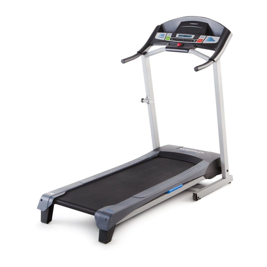
CADENCE reading this manual, please see the front cover of this ® R 5.2 treadmill. The CADENCE R 5.2 treadmill offers a manual. To help us assist you, note the product model selection of features designed to make your workouts number and serial number before contacting us. -
Page 6: Assembly
ASSEMBLY To hire an authorized service technician to assemble the treadmill, call 1-800-445-2480. Assembly requires two persons. Set the treadmill in a cleared area and remove all packing materials; do not dispose of the pack- ing materials until assembly is completed. Note: After shipping, there may be an oily substance on the exterior of the treadmill. - Page 7 2. Attach the Handrails (69) to the Upright (73) with four M10 x 45mm Screws (2). Start all four Screws, and then tighten them. 3. With the help of a second person, hold the con- sole assembly near the Upright (73). Remove Console Assembly the tie from the Upright Wire (71).
- Page 8 4. Attach the console assembly to the Upright (73) and the Handrails (69) with six M4.2 x 19mm Console Assembly Screws (3). Be careful not to pinch the wires. 5. Attach the Latch Housing (72) to the left Upright (73) with two #10 x 1" Tek Screws (35); start both Screws, and then tighten them.
-
Page 9: To Connect Power Cord
OPERATION AND ADJUSTMENT HOW TO CONNECT THE POWER CORD nominal 120-volt circuit capable of carrying 15 or more amps. To avoid overloading the circuit, do Use a Surge Suppressor not plug other electrical devices, except for low- power devices such as cell phone chargers, into Your treadmill, like other electronic equipment, can be the surge suppressor or into an outlet on the same circuit. - Page 10 CONSOLE DIAGRAM Thumb Heart Rate Monitor Clip FEATURES OF THE CONSOLE IMPORTANT: If there is a sheet of plastic on the face of the console, remove the plastic. To prevent damage to the walking platform, wear clean ath- The treadmill console offers a selection of features designed to make your workouts more effective.
-
Page 11: How To Turn On Power
HOW TO TURN ON THE POWER HOW TO USE THE MANUAL MODE IMPORTANT: If the treadmill has been exposed to 1. Insert the key into the console. cold temperatures, allow it to warm to room tem- perature before turning on the power. If you do not See HOW TO TURN ON THE POWER at the left. - Page 12 4. Follow your progress with the displays. 5. Measure your heart rate if desired. The track—The track To measure your heart rate, stand on the foot rails and place your thumb on the heart rate moni- represents a distance tor (see the drawing on page 10). Do not press of 1/4 mile (400 m).
-
Page 13: To Use A Preset Workout
HOW TO USE A PRESET WORKOUT and the next segment of the profile will begin to flash. If a different speed setting is programmed for 1. Insert the key into the console. the next segment of the workout, the new speed setting will flash in the display to alert you. -
Page 14: To Change Incline Of Treadmill
THE INFORMATION MODE HOW TO CHANGE THE INCLINE OF THE TREADMILL The console features an information mode that allows To vary the intensity of your exercise, you can change you to turn on and turn off the demo mode and to the incline of the treadmill. -
Page 15: How To Fold And Move The Treadmill
HOW TO FOLD AND MOVE THE TREADMILL HOW TO FOLD THE TREADMILL HOW TO MOVE THE TREADMILL Before folding the treadmill, remove the key and Before moving the treadmill, fold it as described at the unplug the power cord. CAUTION: You must be left. -
Page 16: Troubleshooting
TROUBLESHOOTING Most treadmill problems can be solved by follow- d. If the treadmill still will not run, please see the front ing the simple steps below. Find the symptom that cover of this manual. applies, and follow the steps listed. If further assis- tance is needed, see the front cover of this manual. - Page 17 Remove the five indicated M4.2 x 19mm Washer b. If the walking belt is overtightened, treadmill per- Head Screws (9). Then, carefully remove the Motor formance may decrease and the walking belt may Hood (56). become damaged. Remove the key and UNPLUG THE POWER CORD.
-
Page 18: Walking Belt Is Off-Center/Slips
SYMPTOM: The walking belt is off-center or slips b. If the walking belt slips when walked on, first when walked on remove the key and UNPLUG THE POWER CORD. Using the hex key, turn both idler roller a. If the walking belt is off-center, first remove the screws clockwise, 1/4 of a turn. -
Page 19: Exercise Guidelines
EXERCISE GUIDELINES Burning Fat—To burn fat effectively, you must exer- WARNING: cise at a low intensity level for a sustained period of Before beginning this time. During the first few minutes of exercise, your or any exercise program, consult your physi- body uses carbohydrate calories for energy. -
Page 20: Part List
PART LIST Model No. WLTL29712.1 R0912A Key No. Qty. Description Key No. Qty. Description M10 x 65mm Screw Reed Switch Clamp M10 x 45mm Screw Magnet M4.2 x 19mm Screw Drive Belt M8 x 35mm Screw Drive Roller/Pulley M4.2 x 13mm Washer Head Screw Walking Belt M4.2 x 13mm Screw Walking Platform... -
Page 21: Exploded Drawing
EXPLODED DRAWING A Model No. WLTL29712.1 R0912A... - Page 22 EXPLODED DRAWING B Model No. WLTL29712.1 R0912A 23 11...
- Page 23 EXPLODED DRAWING C Model No. WLTL29712.1 R0912A...
-
Page 24: Ordering Replacement Parts
ORDERING REPLACEMENT PARTS To order replacement parts, please see the front cover of this manual. To help us assist you, be prepared to pro- vide the following information when contacting us: • the model number and serial number of the product (see the front cover of this manual) •...