Schwinn IC2 Indoor Cycling Bike Assembly Manual
Assembly and owner's manual
Hide thumbs
Also See for IC2 Indoor Cycling Bike:
- Manual (2 pages) ,
- Service manual (66 pages) ,
- Assembly manual / owner's manual (24 pages)

Related Manuals for Schwinn IC2 Indoor Cycling Bike


Summary of Contents for Schwinn IC2 Indoor Cycling Bike
- Page 1 Manual en Español Latino Americano: ASSEMBLY MANUAL / OWNER’S MANUAL http://www.schwinnfitness.com...
-
Page 2: Table Of Contents
Printed in China | © 2011 Nautilus, Inc., All rights reserved. ™ and ® indicate a trademark or registered trademark. Nautilus, Inc. (www.NautilusInc.com) trademarks include NAUTILUS®, BOWFLEX®, SCHWINN® and UNIVERSAL® and respective logos. Other trademarks are the property of their respective owners. -
Page 3: Important Safety Instructions - Assembly
IMpORTANT SAfETY INSTRUCTIONS — ASSEMBLY This icon means a potentially hazardous situation which, if not avoided, could result in death or serious injury. Obey the following warnings: Read and understand all warnings on this machine. Carefully read and understand the Assembly instructions. •... -
Page 4: Safety Warning Labels / Serial Number
SAfETY WARNINg LABELS ANd SERIAL NUMBER • • • • 250lbs. (113kg). • • • • • • 250lbs. (113kg). • •... -
Page 5: Specifications
SpECIfICATIONS Maximum User Weight: 250 lbs. (113 kg) 2 AA batteries (LR6) - not Power Requirements: included Operational Voltage: 1.0 - 3.3VDC 48.4” (123cm) 44.5” (113cm) 22.2” (56.4cm) Before Assembly Select the area where you are going to set up and operate your machine. For safe operation, the location must be on a hard, level surface. -
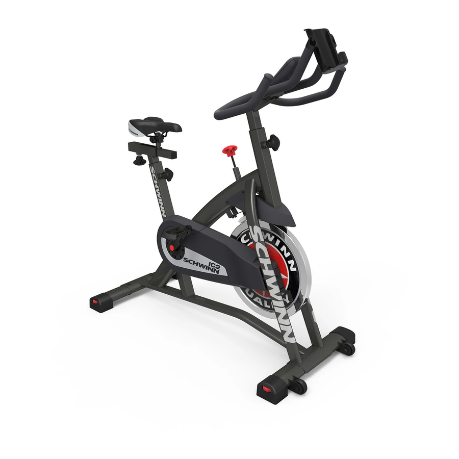
Page 6: Parts
pARTS Item Description Item Description Main Frame Seat Post Front Stabilizer Handlebar Post Rear Stabilizer Handlebar Pedal, Right Water Bottle Holder Pedal, Left Console Seat... -
Page 7: Hardware
HARdWARE / TOOLS Item Description Button Head Hex Screw M8 x 56 Button Head Hex Screw M8 x 20 Flat Washer M8 Lock Nut M8 Pan Head Phillips Screw M6 x 50 Flat Washer M6 Tools Included Not Included 6 mm (recommended) -
Page 8: Assembly
ASSEMBLY 1. Attach Stabilizers to Frame Assembly... - Page 9 2. Attach Seat to Seat Post and Frame NOTICE: Slide the Seat (6) onto the Seat Post (7) and install the Seat Post in the Frame. Make sure the adjustment knob (7a) engages the holes in the Seat Post. Be sure the Seat is straight. Tighten the bolt (6b) and nut (6c) on the Seat bracket (6a) to hold the Seat in position.
- Page 10 3. Attach Handlebars to Handlebar Post 4. Install Handlebar Assembly on Frame NOTICE: Make sure the adjustment knob (8a) engages the holes in the Handlebar Post.
- Page 11 5. Attach Pedals to Frame Assembly Note: The Left Pedal is reverse-threaded. Be sure to attach Pedals on the proper side of the Bike. Orientation is based from a seated position on the bike. The Left Pedal has an “L”, the Right Pedal an “R”.
- Page 12 6. Attach Water Bottle Holder to Handlebar 7. Install Batteries in Console Note: The console uses AA size batteries (LR6), which are not included. Make sure that the batteries point in the direction of the +/– indicators in the battery bay.
- Page 13 8. Connect and Attach the Console NOTICE: Do not crimp Console Cable.
-
Page 14: Leveling The Bike
9. Final Inspection Inspect your machine to ensure that all hardware is tight and components are properly assembled. Be sure to record the serial number in the field provided at the front of this manual. Refer to the Safety Warning Labels and Serial Number section of this manual. Do not use or put the machine into service until the machine has been fully assembled and inspected for correct performance in accordance with the Owner’s Manual. -
Page 15: Important Safety Instructions - Owner's
IMpORTANT SAfETY INSTRUCTIONS This icon means a potentially hazardous situation which, if not avoided, could result in death or serious injury. Before using this equipment, obey the following warnings: Read and understand the complete Manual. Keep the Manual for future reference. Read and understand all warnings on this machine. -
Page 16: Features
fEATURES Console Pedals Handlebar Assembly Flywheel Adjustment Knob Brake Assembly Brake/Resistance Knob Chain Guard Seat Transport Wheels Seat Slider Battery Bay Stabilizers Water Bottle Holder Levelers... -
Page 17: Emergency Stop
Emergency Stop To stop the pedals immediately, push down hard on the Brake/Resistance Knob. Console Features The Console provides information about your workout on the display screen. You can also use the button to get access to information about console settings. Front Back Battery bay... - Page 18 Pedal revolutions Time Calories Numeric display Distance Speed The RPM display field shows the machine revolutions per minute (RPM). The maximum display is 200. The CAL display field shows the estimated calories that you have burned during the exercise. The maximum display is 9999.
-
Page 19: Operations
OpERATIONS What to Wear Wear rubber-soled athletic shoes or appropriate cycling shoes. You will need the appropriate clothes for exercise that allow you to move freely. How Often Should You Exercise Consult a physician before you start an exercise program. Stop exercising if you feel pain or tightness in your chest, become short of breath, or feel faint. -
Page 20: Workout Mode
Handlebar Adjustment Loosen and pull the adjustment knob on the handlebar mount. Adjust the handlebar assembly to the desired height. Release the adjustment knob to engage the locking pin. Be sure that the pin is fully engaged and fully tighten the knob. Do not lift the Handlebar Post above the MAX mark on the tube. -
Page 21: Service Mode
SERvICE MOdE Service Mode lets you set the units of measure to either English or Metric, see machine statistics and firmware version (for technician use only). When the Console is in Workout Mode or Pause Mode, push and hold down the button for 5 seconds to go into Service Mode. -
Page 22: Maintenance
MAINTENANCE Read all maintenance instructions fully before you start any repair work. In some conditions, an assistant is necessary to do the necessary tasks. Equipment must be regularly examined for damage and repairs. The owner is responsible to make sure that regular maintenance is done. Worn, damaged or loose components must be repaired or replaced immediately. - Page 23 Maintenance Parts A Console Pedals Speed Sensor Magnet B Handlebars Seat RPM Sensor C Brake/Resistance Knob Seat Post Sprocket drive D Brake Assembly Adjustment Knob Data Cable E Chain Guard Chain Guard Door Flywheel F Chain Guard Inside M Levelers Brake Cover G Crank Arms Chain...
-
Page 24: Chain Lubrication
Chain Lubrication Remove the chain guard door and apply a few drops of bike chain oil to the chain. Do not apply oil when the chain is moving. Note: Use caution to avoid staining clothes or carpet. Replacing the Console Batteries The Console display will show “Batt”... -
Page 25: Troubleshooting
TROUBLESHOOTINg Condition/Problem Things to Check Solution Console will not power up/turn Batteries Make sure batteries are on/start installed correctly. If batteries are correctly installed, replace with a set of new batteries. Speed displayed is not Display set to wrong unit of Change display units. - Page 26 Unit rocks/does not sit level Check leveler adjustment Leveling feet may be turned in or out to level bike. Check surface under unit Adjustment may not be able to compensate for extremely uneven surfaces. Move bike to level area. Pedals loose Check pedal to crank connec- Pedal should be tightened tion...
- Page 28 Nautilus Bowflex Schwinn fitness Universal ® ® ® ® 004-4625.060611.A...