Bowflex Xtreme 2 Assembly Instructions Manual
Assembly manual
Hide thumbs
Also See for Xtreme 2:
- Owner's manual (73 pages) ,
- Assembly instructions manual (21 pages)
Table of Contents
Advertisement
Advertisement
Table of Contents

Related Manuals for Bowflex Xtreme 2


Summary of Contents for Bowflex Xtreme 2
- Page 1 Assembly Instructions 17496 Rev B (02/2007)
-
Page 2: Parts Diagram
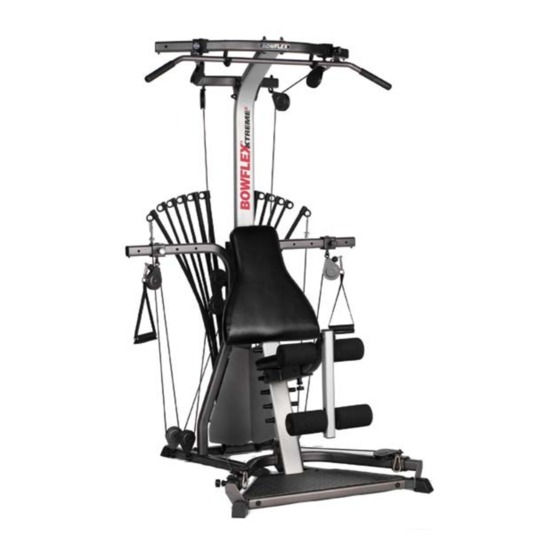
Get To Know Your Machine The BOWFLEX Xtreme 2 Home Gym ® ® FRONT... -
Page 3: Parts And Assembly
Parts and Assembly Tips Parts List Hardware List Item Qty. Description Item Qty. Description STANDING PLATFORM SCREW, 4.2mm X 12mm SHROUD SCREW RIGHT FRAME RAIL SCREW, #10 X 1" SELF DRILLING LEFT FRAME RAIL BOLT, 1/4" X 1/2" SOCKET HEAD CAP REAR CROSS BAR BOLT, 5/16"... -
Page 4: Assembly Hardware
Bowflex® Xtreme®2 Home Gym Assembly Hardware Item #: D Item #: A Item #: B Item #: C Qty.: Qty.: Qty.: Qty.: Descr: 5/16" X 3/4" Descr: 4.2mm X 12mm Descr: #10 X 1" Self Descr: 1/4" X 1/2" Hex Head... -
Page 5: Basic Assembly Principles
2. When tightening a locknut on a bolt, use a combination wrench to grip the locknut and ensure that it is fastened securely. 3. When attaching two pieces, gently lift and look through the bolt holes to help guide the bolt through the holes. 4. As a general rule, and for all bolts and nuts on your Bowflex ®... -
Page 6: Assembly Guide
Assembly Guide Step 1: Assemble the Base Frame Assembly Figure 1 Locate the following items: • Item #1 - Standing Platform • Item #2 - Right Frame Rail • Item #3 - Left Frame Rail • Item #4 - Rear Cross Bar •... -
Page 7: Attach Lower Lat Tower
Step 3: Attach the Lower Lat Tower to the Base Figure 3 Frame Assembly Lower Lat Tower Assembly Locate the following items: • From Step 1 - Base Frame Assembly • From Step 2 - Lower Lat Tower Assembly • Item #F - (2) 3/8" X 3/4" Hex Head Bolts •... -
Page 8: Install Right/Left Squat Frame Rails
Step 5: Install the Right and Left Squat Frame Rails Figure 5 Locate the following items: • Item #8 - Right Squat Frame Rail • Item #9 - Left Squat Frame Rail • Item #10 - Right Squat Frame Foot Assembly •... - Page 9 Step 6: Attach the Pulley Arms Figure 6 Locate the following items: • Items #12 and #13 - Right and Left Pulley Arms • From Step 5 - Main Assembly • Item #F - (4) 3/8" X 3/4" Hex Head Bolts •...
- Page 10 Step 8: Attach the Cable Shroud to the Pulley Arms Figure 8 Locate the following items: • Item #23 - Cable Shroud • From Step 7 - Main Assembly • Item #A - (4) 4.2mm X 12mm Self Drilling Screws •...
- Page 11 Step 10: Attach the Seat Pad to the Seat Support Rail Figure 10 Locate the following items: • From Step 9 - Seat Backbone w/ Seat Assembly • From Step 8 - Main Assembly With the Seat Pad (Item #16) cushion side up, align the top two hooks on the Seat Backbone with the lowest pair of “pins”...
-
Page 12: Attach Front/Rear Lat Cross Bar
Step 12: Attach Front Lat Cross Bar to Upper Lat Tower Figure 12 Locate the following items: • Item #25 - Upper Lat Tower • Item #26 - Front Lat Cross Bar • Item #H - (2) 3/8" X 3" Hex Head Bolts •... - Page 13 Step 14: Attach Upper Lat Tower to the Lower Assembly Figure 14 Locate the following items: Upper Lat Tower Assembly • From Step 13 - Upper Lat Tower Assembly • From Step 11 - Main Assembly • Item #F - (3) 3/8" X 3/4" Hex Head Bolts •...
-
Page 14: Bowflex Xtreme2 Pulleys & Cables
Step 16: Bowflex® Xtreme®2 Home Gym Pulleys The Figure below shows all Pulleys on the Bowflex® Xtreme®2 home gym. Subsequent images illustrate how to connect and route each of the Cables through the Pulleys. Connecting the Cables is much easier with a second person assisting you. -
Page 15: Lat Pulley Housing
Figure 17- Lat Pulley Housing Lat Pulley Housing Washer Hex Head Bolt Towards the Rear of the Machine Towards the Front of the Machine NOTE: Pulleys shown are seperated Grasp and hold for clarity. Pulleys do NOT Cables here come apart on your machine. Left Pulley Cable Right Pulley Cable Step 17 - Cable &... - Page 16 Figure 18 - Lat Pulley Housing Lat Pulley Housing Washer Hex Head Bolt Referred to as: (2) Pulley Towards the Front of the Machine Towards the Rear of the Machine Step 18 - Cable & Pulley Routing Connect the Pulleys and Cables to the Lat Pulley Housing Locate the following items: •...
-
Page 17: Lat Tower Pulleys
Step 19 - Cable & Figure 19 - Lat Tower Pulleys Pulley Routing Connect Rod Cables through the Right (3) Floating and Lat Tower Pulleys Locate the following items: • 3 & 8 Floating Pulleys Cable End Stop Ball (connected unit) •... -
Page 18: Cable End Stop Ball With Core
Step 19b - Cable & Pulley Routing Connect Cable End Stop Ball with Core Cable End Stop Ball Ferrule Figure 19b - Cable End Stop Ball with Core Cable Core Step 19c - Cable & Pulley Routing Connect Rod Cables through Left (3) Floating Figure 19c - Lat Tower Pulleys and Lat Tower Pulleys Repeat with Left Rod Cables and (3) &... -
Page 19: Right Main Assembly Pulleys
Slide the Right Squat Frame Pulley (6) to the furthest back hole, as indicated in Figure 20. Unwrap the Right Squat Cable from the (6) Pulley and guide the Cable under the Cable Shroud (with the Bowflex® Xtreme®2 Logos), threading under and through the Rear Cross Bar Pulley (7), and up through the Floating (8) Pulley. - Page 20 Figure 20b - Left Main Assembly Pulleys Left Squat Cable Cable Shroud Step 20b - Cable & Pulley Routing Connect Left Squat Cable through the Floating and Main Assembly Pulleys Repeat the same procedure completed during Step 20 for the Left Squat Cable.
- Page 21 Step 21: Install the Leg Extension Figure 21 Locate the following items: • Item #18 - Lock Knob • Item #19 - Leg Extension Assembly Remove the Seat (installed in Step 10), and turn it cushion side down. Insert the Leg Extension Assembly (Item #19) into the open end of the Seat Backbone (Item #17).
- Page 22 Carefully go over the entire Bowflex Xtreme 2 home gym ® ® assembly, and tighten all bolts, nuts and other hardware before using your Bowflex Xtreme 2 home gym. ® ® CONGRATULATIONS! You have successfully assembled your Bowflex® Xtreme®2 home gym!
- Page 23 ® improving our manuals, please call 800-628-8458 for assistance” © 2004, The Nautilus Group, Inc. 16400 SE Nautilus Drive, Vancouver, WA 98683. Nautilus®, Power Rod® and the Bowflex® Xtreme®2 home gym and Nautilus® logos are registered trademarks of Nautilus, Inc.