Table of Contents
Advertisement
•
Please read the users guide before proceeding with your
installations. Serious damage may occur if the procedure is not
followed properly.
•
This motherboard does not support CPUs with a Vcore higher than 1.6
volts. Please make sure the CPU you are using 1.6 volts or below.
Check the CPU specification before you insert it in the CPU socket.
•
AGP cards running at 3.3v are not supported. Only AGP cards running
at 1.5v (most 4x or 8x AGP cards) are supported on this motherboard.
•
Please make sure that your memory modules are inserted correctly.
They can go in only one way, and should fit completely in the socket
without sticking out. Failure to do so will damage your motherboard
and memory module.
•
An ATX 12V power supply (Power supply for Pentium 4 system) is
required for the system to operate normally. (Preferably 350 watts for
minimal loading or 400 watts for fully loaded system).
•
If you have any problem getting your system to work, please follow the
troubleshooting tips in your user manual.
•
On some motherboards, the actual chipset cooler may differ from the
chipset cooler as shown on the picture or on the box. However, the
chipset fan on the motherboard is of the same quality and will work just
as well as the one shown in the picture. (The chipset cooler is as
sufficient as the chipset fan based on a different design.)
•
For answers to Technical questions, please visit SOYO tech support
link at
http://www.soyousa.com/support
http://www.soyousa.com/kb.
and
Advertisement
Table of Contents

Related Manuals for SOYO ATX 12V


Summary of Contents for SOYO ATX 12V
- Page 1 Failure to do so will damage your motherboard and memory module. • An ATX 12V power supply (Power supply for Pentium 4 system) is required for the system to operate normally. (Preferably 350 watts for minimal loading or 400 watts for fully loaded system).
- Page 2 SY-P4I865PE Plus DRAGON 2 Motherboard **************************************************** mPGA Socket 478 Processor supported Intel 865PE AGP/PCI 400/533/800 MHz Front Side Bus supported ATX 12V Form Factor **************************************************** User's Manual...
- Page 3 SOYO ™ Copyright © 2003 by Soyo Computer Inc. Trademarks: Soyo is the registered trademark of Soyo Computer Inc. All trademarks are the properties of their owners. Product Rights: All names of the product and corporate mentioned in this publication are used for identification purposes only.
-
Page 4: Table Of Contents
Table of Contents Table of Contents CHAPTER 1 MOTHERBOARD DESCRIPTION ... 1 INTRODUCTION ... 1 UNPACKING THE MOTHERBOARD ... 1 KEY FEATURES... 3 HANDLING THE MOTHERBOARD ... 4 ELECTROSTATIC DISCHARGE PRECAUTIONS ... 5 SY-P4I865PE P SY-P4I865PE P CHAPTER 2 HARDWARE INSTALLATION... 13 PREPARATIONS... - Page 5 Table of Contents ADVANCED CHIPSET FEATURES ... 63 INTEGRATED PERIPHERALS ... 65 POWER MANAGEMENT SETUP... 71 PNP/PCI CONFIGURATION SETUP... 75 PC HEALTH STATUS... 78 LOAD FAIL-SAFE DEFAULTS ... 79 3-10 LOAD OPTIMIZED DEFAULTS ... 80 3-11 SUPERVISOR PASSWORD ... 81 3-12 USER PASSWORD ...
-
Page 6: Chapter 1 Motherboard Description
MOTHERBOARD DESCRIPTION 1-1 INTRODUCTION The SY-P4I865PE Plus DRAGON 2 AGP/PCI Motherboard is a high-performance Socket 478 processor supported ATX 12V form-factor system board. SY-P4I865PE Plus DRAGON 2 uses the Intel 865PE Chipset technology. This Motherboard is fully compatible with industry standards and adds many technical enhancements. -
Page 7: Sy-P4I865Pe Plus Dragon
Hardware Installation One Back panel Warning: Do not unpack the Motherboard from its anti-static packaging until you are ready to install it. Like most electronic equipment, your Motherboard may be damaged by electrostatic discharge. To avoid permanent damage to components ground yourself while working by using a grounding strap. -
Page 8: Key Features
Hardware Installation 1-3 KEY FEATURES Chipset Memory Super I/O SY- P4I865PE Plus DRAGON 2 Supports Intel® mPGA Socket 478 processors : Pentium® 4 with and without Hyperthreading, Northwood, Prescott (400/533/800MHz FSB) Pentium® 4 Celeron SOYO COMBO Setup CMOS setup menu for complete and easy changing of your CPU settings in CMOS setup, making jumpers obsolete. -
Page 9: Handling The Motherboard
Hardware Installation Storage USB 2.0 Sound Network BIOS Industry standards 1-4 HANDLING THE MOTHERBOARD To avoid damage to your Motherboard, follow these simple rules while unpacking: Before handling the Motherboard, ground yourself by grasping an unpainted portion of the system's metal chassis. Remove the Motherboard from its anti-static packaging. -
Page 10: Electrostatic Discharge Precautions
Hardware Installation Warning: Do not apply power if the Motherboard appears damaged. If there is damage to the board, contact your dealer immediately. 1-5 ELECTROSTATIC DISCHARGE PRECAUTIONS Make sure to ground yourself before handling the Motherboard or other system components. Electrostatic discharge can easily damage the components. -
Page 11: Sy-P4I865Pe Plus Dragon 2 Motherboard Layout
Hardware Installation 1-6 SY-P4I865PE PLUS DRAGON 2 MOTHERBOARD LAYOUT PS/2 KB PS/2 Mouse PS/2 Mouse Connector Connector COM A COM B USBLAN MIC IN / Center & Bass out Audio out / Front out Audio in / Rear out Back Panel SY- P4I865PE Plus DRAGON 2 +12V Power ATX Power... -
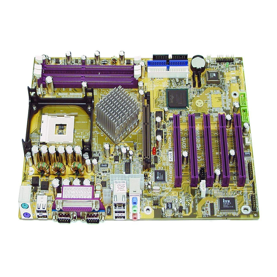
Page 12: Sy-P4I865Pe Plus Dragon 2 Motherboard Components
Hardware Installation 1-7 SY-P4I865PE PLUS DRAGON 2 MOTHERBOARD COMPONENTS SY- P4I865PE Plus DRAGON 2... - Page 13 Hardware Installation +12V Power Connector This is where the Power Supply's +12V ATX connector goes. For a lay-out of this connector please check the F. ATX12V Power Supply paragraph on page 35. ATX Power Supply connector This connector is to connect the ATX connector of your ATX12V compliant power supply to the motherboard.
- Page 14 Hardware Installation CPU Cooling Fan (CPUFAN1) connectors With these connectors you can attach the CPU fan or fans to your motherboard. They supply power and (in the case of CPUFAN1) allow you to monitor the speed of the FAN via the SOYO Hardware Monitor software or via CMOS setup.
- Page 15 23 for more details and lay-outs. 5V Stand-By Indicator LED The ATX 12V power supply will always supply a 5V standby voltage to your motherboard so that it can power on via for example Wake On Lan technology. This LED shows that your ATX 12V power supply is supplying this standby voltage to your motherboard.
- Page 16 Hardware Installation GAMEPORT connector This connector is to attach your gameport connector to. Gameports are used to connect for example joysticks to. For more details check the paragraph on page 30. Serial Infrared (IrDA) device header This header allows you to connect an IrDA receiver to the motherboard.
- Page 17 Hardware Installation SY- P4I865PE Plus DRAGON 2 AC97 Onboard Audio Chip Microphone and LAN Status LED Connector (J30) This connector allows you to extend your microphone connector and LAN Status LED to your front panel. Check the 6. MIC & LED Connector (J30) paragraph on page 34 for a lay-out of this header.
-
Page 18: Chapter 2 Hardware Installation
Hardware Installation HARDWARE INSTALLATION Congratulations on your purchase of SY-P4I865PE Plus DRAGON 2 Motherboard. You are about to install and connect your new Motherboard. Note: Do not unpack the Motherboard from its protective anti-static packaging until you have made the following preparations. -
Page 19: Installation Guide
Hardware Installation 2-2 INSTALLATION GUIDE We will now begin the installation of the Motherboard. Please follow the step-by-step procedure designed to lead you to a complete and correct installation. Step1- Install the Central Processing Unit (CPU). Step2- Install memory modules. Step3- Install expansion cards. - Page 20 Hardware Installation SY- P4I865PE Plus DRAGON 2 2. Align the blunt edge of the CPU with the matching pinhole distinctive edge on the socket. 3. Seat the processor in the socket completely and without forcing.
-
Page 21: Cpu Fan Installation
Hardware Installation 4. Then close the socket handle to secure the CPU in place. Remember to connect the CPU Cooling Fan to the appropriate power connector on the Motherboard. The fan is a key component that will ensure system stability. The fan prevents overheating, therefore prolonging the life of your CPU. -
Page 22: Step 2 Install Memory Module
Hardware Installation Step 2 Install Memory Module This motherboard supports one Dual Channel to your memory, Note that you can use normal DDR memory for Dual Channel to work. Also note that for Dual Channel to work 2 modules of equal size and specifications have to be installed. - Page 23 Hardware Installation Memory Configuration Table If you want to use the Dual Channel feature, please follow the memory configuration table below: Slots DDR_A1 Performance Present 128 bit Installing your memory in a combination different from the table above will still allow your system to work. The Dual Channel feature will not work then however.
-
Page 24: Step 3 Installation Of Expansion Cards
Hardware Installation SY- P4I865PE Plus DRAGON 2 Step 3 Installation of Expansion Cards The motherboard has 1 AGP slot and 5 PCI slots. 1. Read the related expansion card’s instruction document before inserting the expansion card into the computer. 2. Press the expansion card firmly into the expansion slot in the motherboard 3. -
Page 25: Step 4 Connect Cables, Case Wire, And Power Supply
Hardware Installation SY- P4I865PE Plus DRAGON 2 Step 4 Connect cables, case wire, and power supply A.IDE Device Installation (HDD, CD-ROM) Pin 1 IDE 2 IDE 1 Secondary Primary SATA2 SATA1 This Motherboard offers 1 primary (IDE1) IDE device connectors, 1 secondary IDE device connectors (IDE2) and 2 tertiary serial ATA ports. - Page 26 Hardware Installation Note: IDE2 and SATA2 are not bootable, SATA1 and IDE1 are bootable. Note: Only Windows XP can use SATA1, SATA2, IDE1 and IDE2 at the same time. All other operating systems can use any combination from the following table: Parallel ATA connectors Connect the black end of the ATA66/100 flat cable to the IDE device (HDD or CD-ROM) and plug the blue end to the primary (IDE1) or secondary...
- Page 27 Hardware Installation SY- P4I865PE Plus DRAGON 2 Serial ATA connectors You can also plug the serial ATA cable into the serial ATA connector of the motherboard. The other end of the SATA cable goes into your SATA device. Serial ATA Cable Se ria l AT A...
-
Page 28: Floppy Drive Installation
Hardware Installation SY- P4I865PE Plus DRAGON 2 B. Floppy Drive Installation Pin 1 Floppy Drive Connector The system supports 5 possible floppy drive types: 720 KB, 1.2 MB, 1.44 MB, 2.88 MB. In addition, this Motherboard supports a 3-mode (720KB/1.2MB/1.44MB) floppy commonly used in Japan. Connect one side of the 34-pin flat cable to the floppy drive and plug the other end in the floppy drive connector on the Motherboard. -
Page 29: Front Panel Connections
Hardware Installation C. Front Panel Connections Plug the computer case's front panel devices to the corresponding headers on the Motherboard. 1. Power LED Please install according to the following pin assignment: pin 1, 3 are for Power LED. SY- P4I865PE Plus DRAGON 2 Speaker Key Lock Power LED... - Page 30 Hardware Installation 2. Reset Plug the Reset push-button cable into the 2-pin Reset header on the Motherboard. Pushing the Reset button on the front panel will cause the system to restart the boot-up sequence. 3. Speaker Attach the 4-pin PC speaker cable from the case to the Speaker header on the Motherboard.
- Page 31 Hardware Installation 5. IDE LED Attach the 2-pin IDE device LED cable to the corresponding IDE LED header on the Motherboard. This will cause the LED to lighten when an IDE1 or IDE2 (HDD, CD-ROM) device is active. 6. ATX Power On/Off Switch Attach the 2-pin momentary type switch to the PWRBT header for turning On or Off your ATX power supply.
-
Page 32: Back Panel Connections
Hardware Installation D. Back Panel Connections All external devices such as the PS/2 keyboard, PS/2 mouse, printer, modem, USB can be plugged directly into the Motherboard back panel. Only after you have fixed and locked the Motherboard to the computer case can you start connecting the external peripheral devices. - Page 33 Hardware Installation 1. Onboard Serial Ports COMA/COMB External peripherals that use serial transmission scheme include: - serial (RS232) mice - modem. Plug the serial device cables directly into the COMA/COMB 9-pin male connectors located at the rear panel of the Motherboard. 2.
- Page 34 Hardware Installation 5. Universal Serial Bus (USB1/USB2, USB3/USB4, USB20_1/USB20_2) This Motherboard provides 8 USB 2.0 ports for your additional devices. Plug the USB device jack into the available USB connector USB1, USB2, USB3 and USB4. USB20_1 and USB20_2 are available. To make use of these USB ports, purchase a USB cable from your dealer.
-
Page 35: Other Connections
Hardware Installation SY- P4I865PE Plus DRAGON 2 The Gameport has the following lay-out : E. Other Connections 1. Standard Infrared (SIRCON) Plug the 5-pin infrared device cable to the SIRCON header. This will enable the infrared transfer function. This Motherboard meets both the ASKIR and HPSIR specifications. - Page 36 Hardware Installation SY- P4I865PE Plus DRAGON 2 2. Cooling Fan Installation (1) CPU Cooling Fan (CPUFAN1) After you have seated the CPU properly on the processor, attach the 3-pin fan cable to the CPUFAN connector on the Motherboard. To avoid damage to the system, install according to the following pin assignment: CPU Cooling Fan CPUFAN1 Pin Assignment...
- Page 37 Hardware Installation (2) Chassis Cooling Fan (CHAFAN1, CHAFAN2) Some chassis also feature a cooling fan. This Motherboard features a CHAFAN connector to provide 12V power to the chassis fan. Connect the cable from the chassis fan to the CHAFAN 3-pin connector. Install according to the following pin assignment: Note: CPU cooling fan must be installed to prevent CPU from overheating and ensure system stability.
- Page 38 Hardware Installation SY- P4I865PE Plus DRAGON 2 3. Smart Card Reader The smart card reader conforms to the PC/SC Working group standard, and has the following lay-out: 4. CD Line-in (CDIN1) This Motherboard provides one CD-Line-in connectors. Please connect the 4-pin audio cable from your CD-ROM or DVD ROM drive to CDIN1.
- Page 39 Hardware Installation 5. AUX-IN (AUXIN1) This Motherboard provides one AUX-IN connectors. Please connect the 4-pin audio cable from your second CD-ROM or DVD ROM drive to either AUX-IN. Please install according to the following pin assignment: 6. MIC & LED Connector (J30) You can connect the Line-out /MIC in /LAN LED to the front panel of your PC case (If this option is available in your PC case).
-
Page 40: Atx12V Power Supply
ATX. Note 2: When using the Power-On by Keyboard function, please make sure the ATX 12V power supply is able to provide at least 1220mA on the 5V Standby lead (5VSB). SY- P4I865PE Plus DRAGON 2... -
Page 41: Center & Bass Select Connector (Jp30)
Note 4: The 4 pin ATX 12V must be connected to the motherboard. Without this connector, the system cannot boot. Please install the ATX power according to the following pin assignment:... -
Page 42: Pin Assignment
Hardware Installation G. CMOS Clear (JP5) In some cases the CMOS memory may contain wrong data, follow the steps below to clear the CMOS memory. 1. Clear the CMOS memory by momentarily shorting pin 2-3 on jumper JP5. This jumper can be easily identified by its white colored cap. 2. -
Page 43: Step 5 Power On
Hardware Installation Onboard LAN LED Definition When this LED is lit, this means running at 100 mbps, if it is not lit, the Onboard LAN is working at 10 mbps. Step 5 Power On You have now completed the hardware installation of your Motherboard successfully. -
Page 44: Quick Bios Setup
Hardware Installation Repeat this operation until you get the following screen. 3. The BIOS Setup screen appears: Phoenix – Award BIOS CMOS Setup Utility SOYO COMBO Feature Standard CMOS Features Advanced BIOS Features Advanced Chipset Features Integrated Peripherals Power Management Setup PnP/PCI Configurations Esc : Quit F10 : Save &... - Page 45 Hardware Installation Select [STANDARD CMOS SETUP] Step1. Set [Date/Time] and [Floppy drive type], then set [Hard Disk Type] to “Auto”. Select [LOAD OPTIMIZED DEFAULTS] Step2. Select the “LOAD OPTIMIZED DEFAULTS” menu and type “Y” at the prompt to load the BIOS optimal setup. Select [SOYO COMBO FEATURE] Step3.
-
Page 46: Chapter 3 Bios Setup Utility
BIOS Setup Utility BIOS SETUP UTILITY This Motherboard's BIOS setup program uses the ROM PCI BIOS program from Award Software Inc. To enter the Award BIOS program's Main Menu: 1. Turn on or reboot the system. 2. After the diagnostic checks, press the [Del] key to enter the Award BIOS Setup Utility. - Page 47 BIOS Setup Utility Hot Keys: Function keys give you access to a group of commands throughout the BIOS utility. Function Command General Help Previous Values Load Fail-Safe Defaults Load Optimized Defaults Save [Esc] Exit [Enter] Select Value [+/–/PU/PD] SY- P4I865PE Plus DRAGON 2 Description Gives the list of options available for each item.
-
Page 48: Bios Setup Utility
BIOS Setup Utility SAVE AND EXIT SETUP Select the [SAVE & EXIT SETUP] option from the Main Menu to save data to CMOS and exit the setup utility. This option saves all your changes and causes the system to reboot. R O M P C I / I S A C M O S... -
Page 49: Soyo Combo Feature
BIOS Setup Utility 3-1 SOYO COMBO FEATURE This motherboard does not use any hardware jumpers to set the CPU frequency. Instead, CPU settings are software configurable with the BIOS [SOYO COMBO Feature]. After the hardware installation is complete, turn the power switch on, then press the <DEL>... -
Page 50: System Performance
BIOS Setup Utility System Performance Setting System Normal Performance Fast Turbo SOYO COMBO Feature Setting CPU Clock 8X~ 50X Ratio Manual Frequency Auto Select 100 ~ 255 Frequency 1MHz Stepping Disabled Async AGP/PCI 66/33 MHz 73/36 MHz 80/40 MHz DRAM:CPU Auto Ratio x1.33... - Page 51 BIOS Setup Utility SOYO COMBO Feature (Continue) Setting Quick Power Disabled On Self Test Enabled C.I.H. 4-WAY Enabled Protection Disabled Voltage Select Setting CPU Vcore Default Select 1.600 1.550 1.500 1.450 1.400 1.350 1.300 Default DDR Voltage Select 2.9V 2.8V 2.7V AGP Voltage Default...
-
Page 52: Advanced Dram Control
BIOS Setup Utility 3-1.1 Advanced DRAM Control Caution: Change these settings only if you are already familiar with DRAM timing parameters. The [Advanced DRAM Control] option changes the values of the chipset registers. These registers control the timings of your memory. Phoenix –... - Page 53 BIOS Setup Utility CHIPSET FEATURES SETUP (Continue) Setting DRAM RAS# to CAS# Delay DRAM RAS# Precharge 7.8 us Refresh Mode Select 15.6 us 64 us Auto SY- P4I865PE Plus DRAGON 2 Description This item allows you to control DRAM RAS to CAS delay time. This item allow you to control DRAM RAS percharge time.
-
Page 54: Onboard Device
BIOS Setup Utility 3-1.2 Onboard Device The [Onboard Device] option changes the values of the chipset registers. These registers control the system options in the computer. Phoenix – Award BIOS CMOS Setup Utility AC97 Audio LAN Chip Enter:Select :Move F5:Previous Values After you have completed the changes, press [Esc] and follow the instructions on your screen to save your settings or exit without saving. -
Page 55: Onchip Ide Device
BIOS Setup Utility 3-1.3 OnChip IDE Device Caution: Change these settings only if you are already familiar with the IDE settings. The [OnChip IDE Device] option changes the settings of the 82801EB (ICH5) IDE controller. These settings do not influence the HighPoint 372N or Silicon Image Sil3112 controllers. - Page 56 BIOS Setup Utility CHIPSET FEATURES SETUP Setting IDE 1,2 /SATA 1,2 IDE only SATA only Pri IDE+SATA SATA+Sec IDE IDE + SATA IDE HDD Block Disabled Mode Enabled IDE DMA transfer Enabled access Disabled SY- P4I865PE Plus DRAGON 2 Description Only enabled IDE1,2.
- Page 57 BIOS Setup Utility IDE Device Controls On-Chip PCI IDE Primary Secondary Primary Master PIO Primary Slave PIO Secondary Master PIO Secondary Slave PIO Primary Master UDMA Primary Slave UDMA Secondary Master UDMA Secondary Slave UDMA SY- P4I865PE Plus DRAGON 2 Setting Description Disabled...
- Page 58 BIOS Setup Utility 3-1.4 Boot Device Order The [Boot Device Order] option allows you to change the order in which your system scans for devices to boot from. Note: That SATA 1 and SATA 2 are not bootable. Phoenix – Award BIOS CMOS Setup Utility First Boot Device Second Boot Device Third Boot Device...
- Page 59 BIOS Setup Utility System Boot Control Settings Setting First Floppy /Second/Third LS120 Boot Device IDE1/SATA1 CDROM ZIP100 Other Device Disabled Boot Other Disabled Device Enabled SY- P4I865PE Plus DRAGON 2 Description Selects the order in which your system scans for devices to boot from (First the first boot device, then the second, etc…).
-
Page 60: Standard Cmos Setup
BIOS Setup Utility 3-2 STANDARD CMOS SETUP Select the [STANDARD CMOS SETUP] option from the Main Menu and press [Enter] key. Phoenix – Award BIOS CMOS Setup Utility Date (mm:dd:yy) Time (hh:mm:ss) IDE Primary Master IDE Primary Slave IDE Secondary Master IDE Secondary Slave Drive A Floppy 3 Mode Support... -
Page 61: Floppy Drives
BIOS Setup Utility Hard Disks Type & Mode Choose the type and mode for the hard disks that you have already installed. Primary Setting (Secondary) Master & Slave IDE HDD Press Auto-Detection Enter IDE Primary Auto Slave (User Type) User None Access Mode Auto... - Page 62 BIOS Setup Utility Others Optional Setting EGA/VGA Video CGA 40 CGA 80 MONO (Monochrome) ALL Errors Halt On No Errors All, But Keyboard All, But Diskette All, But Disk/Key SY- P4I865PE Plus DRAGON 2 Description Select the video mode. When the BIOS detects system errors, this function will stop the system.
-
Page 63: Advanced Bios Features
BIOS Setup Utility 3-3 ADVANCED BIOS FEATURES Select the [Advanced BIOS Features] option from the Main Menu and press [Enter] key. Phoenix – Award BIOS CMOS Setup Utility Virus Warning CPU L1 & L2 Cache CPU L2 Cache ECC Checking Boot Up Floppy Seek Boot Up NumLock Status Gate A20 Option... -
Page 64: Virus Warning
BIOS Setup Utility Virus Warning Setting Disabled Virus Warning Enabled Cache Memory Options CPU L1 & L2 Cache CPU L2 Cache ECC Checking Boot Up Floppy Seek Setting Boot Up Floppy Disabled Seek Enabled SY- P4I865PE Plus DRAGON 2 Description Allows you to choose the VIRUS warning feature for IDE Hard Disk boot sector... - Page 65 BIOS Setup Utility Boot Up NumLock Status Setting Boot Up NumLock Status Gate A20 Options Setting Normal Gate A20 Options Fast Typematic Settings Typematic Rate Setting The following [Typematic Rate] and [Typematic Delay] fields are active only if [Typematic Rate Setting] is set to [Enabled] Typematic Rate Typematic Delay SY- P4I865PE Plus DRAGON 2...
-
Page 66: Security Option
BIOS Setup Utility Security Option Use this feature to prevent unauthorized system boot-up or use of BIOS Setup. The following table describes the security settings. Setting Security Option Setup System Disabled APIC Mode Enabled MPS Version Control for OS 1.4 Other Control Options Setting OS Select for... - Page 67 BIOS Setup Utility LOGO Show Setting Disabled Full Screen LOGO Show Enabled EPA LOGO LOG0 SELECT LOG1 Small Disabled Logo(EPA) Enabled Show SY- P4I865PE Plus DRAGON 2 Description Set Enabled to Show Logo (DRAGON). Allows user to display SOYO logo or own logo. Logo-0 shows SOYO logo, Logo-1 shows user logo.
-
Page 68: Advanced Chipset Features
BIOS Setup Utility 3-4 ADVANCED CHIPSET FEATURES Caution: Change these settings only if you are already familiar with the Chipset. The [Advanced Chipset Features] option changes the values of the chipset registers. These registers control the system options in the computer. Phoenix –... - Page 69 BIOS Setup Utility CHIPSET FEATURES SETUP Setting System BIOS Disabled Cacheable Enabled Disabled Video BIOS Cacheable Enabled Delay Prior 4Min to Thermal 8Min 16Min 32Min 256M Aperture 128M Size (MB) Init Display PCI Slot First SY- P4I865PE Plus DRAGON 2 Description The ROM area F0000H-FFFFFH is cacheable.
-
Page 70: Integrated Peripherals
BIOS Setup Utility 3-5 INTEGRATED PERIPHERALS Caution: Change these settings only if you are already familiar with the Chipset. The [INTEGRATED PERIPHERALS] option changes the values of the chipset registers. These registers control the system options in the computer. The following screen shows setup default settings. Phoenix –... -
Page 71: Keyboard Controls
BIOS Setup Utility 3-5.1 Onboard USB Device This [Onboard USB Device] option changes the values of the onboard USB controller. The following screen shows setup default setting. Phoenix – Award BIOS CMOS Setup Utility USB Controller USB 2.0 Controller USB Keyboard Support USB Mouse Support Move Enter : Select + / - / PU / PD : Value F10 : Save ESC : Exit... -
Page 72: Superio Device
BIOS Setup Utility 3-5.2 SuperIO Device Caution: Change these settings only if your are already familiar with the Chipset. The [SuperIO Device] option changes the values of the Super I/O controller. The following screen shows setup default settings. Phoenix – Award BIOS CMOS Setup Utility POWER ON Function x KB Power ON Password x Hot Key Power ON... -
Page 73: Onboard Fdc Controller
BIOS Setup Utility Others Optional Setting Password POWER ON Function Hot KEY Mouse Move Mouse Click Any KEY BUTTON-ONLY Disables the Wake-Up by Keyboard 98 If [POWER ON Function] is set to [Password] KB Power ON Enter (your Password password) If [POWER ON Function] is set to [Hot Key] Hot Key Power Ctrl-F1~F12... - Page 74 BIOS Setup Utility Onboard Serial Ports Setting UART Mode Normal Select IrDA ASKIR If [UART Mode Select] is set to [IrDA]/[ASKIR] Half UR2 Duplex Mode Full Onboard Parallel Ports Setting Onboard Parallel Disabled Port 378/IRQ7 3BC/IRQ7 278/IRQ5 Parallel Port Mode ECP+EPP If [Parallel Port Mode] is set to [ECP] mode ECP Mode use...
- Page 75 BIOS Setup Utility Others Optional Setting PWRON After PWR-Fail Former-Sts The system will return to the Game Port Address Disabled Midi Port Address Disabled If [Midi Port Address] is set to [330]/[300] mode Midi Port IRQ SY- P4I865PE Plus DRAGON 2 Description The system will switch on when power comes back...
-
Page 76: Power Management Setup
BIOS Setup Utility 3-6 POWER MANAGEMENT SETUP The [POWER MANAGEMENT SETUP] sets the system's power saving functions. Phoenix – Award BIOS CMOS Setup Utility ACPI Suspend Type x Run VGABIOS if S3 Resume Auto Power Management Video Off Method Video Off In Suspend Suspend Type MODEM Use IRQ Suspend Mode... - Page 77 BIOS Setup Utility Power Management Controls Setting S1(POS) ACPI Suspend Type S3(STR) S1 & S3 Auto VGABIOS if S3 Resume User Define Power Management Min Saving Max Saving Video Off Method Sync+Blank Blank screen DPMS Video Off In Suspend Stop Grant Suspend Type PwrOn Suspend...
- Page 78 BIOS Setup Utility Power Management Controls (Continue) Setting Disabled HDD Power Down 1-15Min Soft-Off by Instant-off Turns off the system power instant PWR-BTTN Delay 4 Sec. Wake-Up by Disabled PCI card Enabled Disabled Power On by Ring Enabled Disabled USB KB Wake Up From S3 Enabled Resume by...
- Page 79 BIOS Setup Utility Reload Global Timer Events Setting Disabled IDE0, IDE1 Primary Enabled Secondary FDD, COM, LPT Disabled Port Enabled PCI PIRQ [A-D]# Disabled Enabled SY- P4I865PE Plus DRAGON 2 Description In effect, the system remains alert for anything which occurs to a device which is configured as Enabled.
-
Page 80: Pnp/Pci Configuration Setup
BIOS Setup Utility 3-7 PNP/PCI CONFIGURATION SETUP This option sets the Motherboard's PCI configuration. Phoenix – Award BIOS CMOS Setup Utility Reset Configuration Data Resources Controlled By x IRQ Resources PCI/VGA Palette Snoop Assign IRQ For VGA Assign IRQ For USB INT Pin 1 Assignment INT Pin 2 Assignment INT Pin 3 Assignment... -
Page 81: Pnp/Pci Configuration Controls
BIOS Setup Utility PNP/PCI Configuration Controls Setting Reset Disabled Retain PnP configuration Configuration Data Enabled Manual Resources Controlled By Required to assign IRQ-# and DMA-# to PCI or ISA PnP manually. IRQ-3,4,5,7,9,10,11,12,14,15 assigned to: _ DMA-0,1,3,5,6,7 assigned to: _ Auto (ESCD) If [Resources Controlled By] is set to [Manual] IRQ-#... - Page 82 BIOS Setup Utility PNP/PCI Configuration Setup (Continued) Setting Interrupt How to set the BIOS to release the IRQ to the PnP Interrupt pool: Line PnP / PCI configuration IRQ 15 IRQ 15: PCI / ISA PnP On-Chip Secondary PCI IDE: disabled IRQ 14 IRQ 14: PCI / ISA PnP On-Chip Primary PCI IDE: IRQ 12...
-
Page 83: Pc Health Status
BIOS Setup Utility 3-8 PC HEALTH STATUS This option sets the Motherboard's PC Health Status. Phoenix – Award BIOS CMOS Setup Utility CPU Vcore +3.3V +12V DRAM Voltage AGP Voltage CPU Temperature CHA Temperature CPUFAN1Speed CHAFAN1 Speed Move Enter:Select F5:Previous Values CPU Device Monitoring Setting CPU Vcore,... -
Page 84: Load Fail-Safe Defaults
BIOS Setup Utility 3-9 LOAD FAIL-SAFE DEFAULTS Select the [Load Fail-Safe Defaults] option from the Main Menu to load a pre-defined safe bios settings. This option is recommended if you have instability issues. Phoenix – Award BIOS CMOS Setup Utility SOYO COMBO Feature Standard CMOS Features Advanced BIOS Features... -
Page 85: Load Optimized Defaults
BIOS Setup Utility 3-10 LOAD OPTIMIZED DEFAULTS Select the [Load Optimized Defaults] option from the Main Menu to load the pre-defined optimized BIOS settings. Phoenix – Award BIOS CMOS Setup Utility SOYO COMBO Feature Standard CMOS Features Advanced BIOS Features Advanced Chipset Features Integrated Peripherals Load Optimized Defaults (Y/N)? Y... -
Page 86: Supervisor Password
BIOS Setup Utility 3-11 SUPERVISOR PASSWORD Based on the setting you have made in the [Security Option] of the [Advanced BIOS Feature] section, the password prevents access to the system or the setup program by unauthorized users. Follow this procedure to set a new password or disable the password: Choose [Advanced BIOS Feature] in the Main Menu and press [Enter]. -
Page 87: User Password
BIOS Setup Utility Enter your new password and press [Enter]. The following message appears, prompting to confirm the new password: Re-enter your password and then press [Enter] to exit to the Main Menu. This diagram outlines the password selection procedure: Type the Password Type the Password and Press: <Enter>... -
Page 88: Boot Menu
BIOS Setup Utility Boot Menu Boot Menu enables user to boot-up on different boot device without going into the BIOS setup. To enable boot Menu, press “ESC” after memory and option ROM (like the HighPoint 372N BIOS) initialization, the user will see a device menu, in which he or she can choose from which device they wish to boot. -
Page 89: Chapter 4 Drivers Installation
Drivers installation DRIVERS INSTALLATION The SOYO-CD will Auto Run only in Windows Based Operating Systems. Your SY-P4I865PE Plus DRAGON 2 Motherboard comes with a CD-ROM labeled “SOYO CD”. The SOYO CD contains a. The user’s manual for your new motherboard in PDF format, b. - Page 90 Drivers installation SY- P4I865PE Plus DRAGON 2 The user's manual files included on the SOYO CD are in PDF (Postscript Document Format). In order to read a PDF file, the appropriate Acrobat Reader software must be installed in your system. Note: The Start Up program automatically detects if the Acrobat Reader utility is already present in your system, and otherwise prompts you on whether or not you want to install it.
- Page 91 Drivers installation Step 2. Install Drivers and Utilities Highlight the driver you want to install and then click ok. The Start Up program displays the drivers available for the particular model of Motherboard you own. We recommend that you only install those drivers Click the Install Drivers button to display the list of drivers software that can be installed with your Motherboard.
- Page 92 Drivers installation C-MEDIA Audio Driver for Win 9x/ME/2000/NT/XP The driver supports 2/4/6 speakers 3D positional audio. P4I865PE DRAGON 2 hardware monitor for Win 9x/ME/2000/NT/ Your motherboard comes with a hardware monitoring IC. By installing this utility Temperatures, Fan speeds and Voltages can be monitored. ITE SIM Card reader Driver/Utility for Win 9X/ME/NT/2K/XP Driver to support the smart card reader.
- Page 93 Drivers installation SY- P4I865PE Plus DRAGON 2 After Windows XP installation, your device manager should look like this:...
- Page 94 Drivers installation SY- P4I865PE Plus DRAGON 2 After driver installation, your Windows XP device manager should look like this: Note: To install the USB 2.0 driver, please update to Windows XP service pack 1. Check chapter 5 for more info.
- Page 95 Drivers installation SY- P4I865PE Plus DRAGON 2 Drivers directory list in the CD driver...
-
Page 96: Chapter 5 Intel Usb 2.0 Driver Installation
Intel USB 2.0 Driver Installation SY- P4I865PE Plus DRAGON 2 Chapter 5 INTEL USB 2.0 DRIVER INSTALLATION For Windows XP USB 2.0 drivers are available for download using Windows Update for Windows XP. For additional information regarding USB 2.0 support in Windows XP, please visit http://www.microsoft.com/hwdev/bus/USB/default.asp (Windows XP Service Pack1 Include USB2.0 Driver) - Page 97 Intel USB 2.0 Driver Installation SY- P4I865PE Plus DRAGON 2 10.Choose [Search for a suitable driver for my device]. 11.Click [Next]. 12.Choose [Specify a location] under "Optional search locations". 13.Click [Next]. 14.Click [Browse] to specify the file path where the driver is, e.g. "SOYO Dragon CD:\USB2.0\INTEL\2k\EHCI Package\".