Table of Contents
Advertisement
Advertisement
Table of Contents

Related Manuals for SOYO SY-7VBA133U


Summary of Contents for SOYO SY-7VBA133U
- Page 1 SY-7VBA133U Motherboard **************************************************** ® Pentium III & Celeron Processor supported VIA VT82C694T AGP/PCI/ISA Motherboard 66/100/133 MHz Front Side Bus supported ATX Form Factor **************************************************** User's Manual...
- Page 2 It is the policy of SOYO Computer Inc. to respect the valid patent rights of third parties and not to infringe upon or to cause others to infringe upon such rights.
-
Page 3: Table Of Contents
CHAPTER 1 MOTHERBOARD DESCRIPTION......1 INTRODUCTION.............1 UNPACKING THE MOTHERBOARD ......1 KEY FEATURES..............2 HANDLING THE MOTHERBOARD ......5 ELECTROSTATIC DISCHARGE PRECAUTIONS..5 SY-7VBA133U MOTHERBOARD LAYOUT....6 SY-7VBA133U MOTHERBOARD COMPONENTS..7 CHAPTER 2 HARDWARE INSTALLATION ........9 PREPARATIONS..............9 INSTALLATION GUIDE ..........10 QUICK BIOS SETUP.............28 CHAPTER 3 BIOS SETUP UTILITY..........29 SOYO COMBO SETUP ..........32... -
Page 4: Chapter 1 Motherboard Description
MOTHERBOARD DESCRIPTION 1-1 INTRODUCTION The SY-7VBA133U AGP/PCI/ISA Motherboard is a high-performance Socket 370 supported ATX form-factor system board. The SY-7VBA133U uses VIA Chipset technology and supports Socket 370 class processors. This Motherboard is fully compatible with industry standards and adds many technical enhancements. -
Page 5: Key Features
New released Intel Socket 370 CPUs will very likely be supported by the SY-7VBA133U as well. CPU SETTINGS The SY-7VBA133U provides the user with a very complete and convenient CPU setting environment. The CPU settings are all adjusted through the special SOYO COMBO page in the BIOS, therefore rendering the use of jumpers obsolete. -
Page 6: Hardware Monitor
CD-ROM. Power on by modem or alarm If the SY-7VBA133U system is in suspend mode, it can be switched back on through the modem or RTC alarm through this function. This opens a lot of possibilities, such as remote access that switches the system on only after the modem receives a call. - Page 7 This function is indispensable for server systems that need to always be on line. SOYO BONUS PACK COMPLIANCE The SY-7VBA133U complies with all important industry standards. The following underlines the reliability of the SY-7VBA133U, a motherboard to trust. PC99, ACPI compliant...
-
Page 8: Handling The Motherboard
Motherboard Description SY-7VBA133U HANDLING THE MOTHERBOARD To avoid damage to your Motherboard, follow these simple rules while unpacking: Before handling the Motherboard, ground yourself by grasping an unpainted portion of the system's metal chassis. Remove the Motherboard from its anti-static packaging. Hold the Motherboard by the edges and avoid touching its components. -
Page 9: Sy-7Vba133U Motherboard Layout
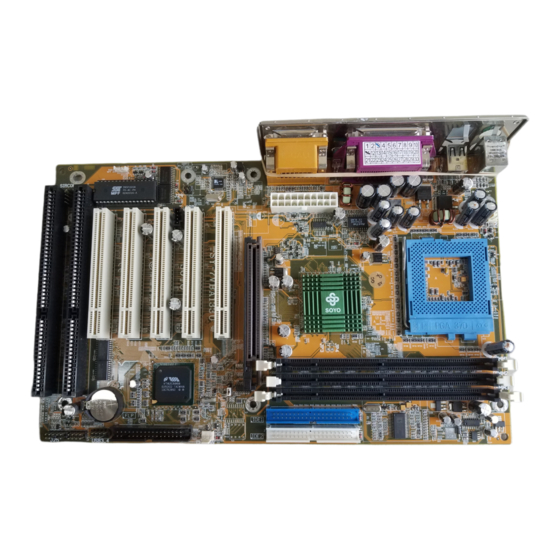
Motherboard Description SY-7VBA133U 1-6 SY-7VBA133U MOTHERBOARD LAYOUT PS/2 KB PS/2 Mouse Connector Connector CPUFAN USB 1 USB 2 COM A COMB ATX Power SDRAM JOYSTICK VT82C694T LINE-OUT SDRAM LINE-IN MIC JACK IDE 1 IDE 2 AGP Slot PCI Slot #1... -
Page 10: Sy-7Vba133U Motherboard Components
Motherboard Description SY-7VBA133U 1-7 SY-7VBA133U MOTHERBOARD COMPONENTS SDRAM SDRAM... - Page 11 Motherboard Description SY-7VBA133U ATX Power Supply CPU Cooling Fan Connector Connector Socket 370 Connector VIA 6946T North Bridge chip DIMM Banks Bus Mastering E-IDE/ATAPI Ports 32-bit AGP Slot 32-bit PCI Mastering Slots CMOS Clear Jumper Chassis Cooling Fan Connector Floppy Disk Drive (FDD) Port...
-
Page 12: Chapter 2 Hardware Installation
Hardware Installation SY-7VBA133U Chapter 2 HARDWARE INSTALLATION Congratulations on your purchase of SY-7VBA133U Motherboard. You are about to install and connect your new Motherboard. Note: Do not unpack the Motherboard from its protective anti-static packaging until you have made the following preparations. -
Page 13: Installation Guide
Motherboard or system. BEGIN THE INSTALLATION Step 1 Install the CPU Your SY-7VBA133U motherboard comes with a CPU retention set kit. The retention set is used to hold the processor attached to the Socket 370 CPU connector on the motherboard. - Page 14 Hardware Installation SY-7VBA133U Align the blunt edge of the CPU with the matching pinhole distinctive edge on the socket. Seat the processor in the socket completely and without forcing. Then close the socket handle to secure the CPU in place.
-
Page 15: Cpu Fan Installation
Hardware Installation SY-7VBA133U Remember to connect the CPU Cooling Fan to the appropriate power connector on the Motherboard. The fan is a key component that will ensure system stability. The fan prevents overheating, therefore prolonging the life of your CPU. -
Page 16: Memory Configuration Table
Hardware Installation SY-7VBA133U Your board recommend a limit of 3 DIMMs or 6 banks at 133 MHz for 1.5GB max memory using unbuffered and Non-ECC DIMM modules. On this motherboard, DRAM speed can be set independent from the CPU front side bus speed. Depending on the DRAM clock speed setting in the BIOS setup, appropriate memory modules must be used. - Page 17 Hardware Installation SY-7VBA133U Replace the screw to secure the slot bracket of the expansion card. Install related driver from the operating system. Step 4 Connect cables, case wires, and power supply A. IDE Device Installation (HDD, CD-ROM) SDRAM SDRAM Pin -1...
- Page 18 Hardware Installation SY-7VBA133U Connect one side of the ATA66/100 flat cable to the IDE device (HDD or CD-ROM) and plug the other end to the primary (IDE1) or secondary (IDE2) directionally keyed IDE connector on the Motherboard. The ATA66/100 cable is backward compatible with ATA33 HDDs.
- Page 19 Hardware Installation SY-7VBA133U The system supports 5 possible floppy drive types: 720 KB, 1.2 MB, 1.44 MB, 2.88 MB, and LS-120. Connect one side of the 34-pin flat cable to the floppy drive and plug the other end to the floppy drive connector on the Motherboard.
-
Page 20: Power Led
Hardware Installation SY-7VBA133U Plug the computer case's front panel devices to the corresponding headers on the Motherboard. 1. Power LED Please install according to the following pin assignment: pin 1,3 are for Power LED. Power LED Pin Assignment 2. Reset Plug the Reset push-button cable into the 2-pin Reset header on the Motherboard. - Page 21 Hardware Installation SY-7VBA133U 4. ACPI LED Connecting the 2-pin ACPI LED cable to the corresponding ACPI LED header will cause the LED to light whenever the system is in ACPI mode. The manufacturer has permanently set this Motherboard in ACPI mode due to most hardware and software compliance to ACPI mode.
- Page 22 Hardware Installation SY-7VBA133U D. Back Panel Connections All external devices such as the PS/2 keyboard, PS/2 mouse, printer, modem, USB can be plugged directly onto the Motherboard back panel. Only after you have fixed and locked the Motherboard to the computer case can you start connecting the external peripheral devices.
- Page 23 Hardware Installation SY-7VBA133U 1. Onboard Serial Ports COMA/COMB External peripherals that use serial transmission scheme include: serial mouse, and modem. Plug the serial device cables directly into the COMA/COMB 9-pin male connectors located at the rear panel of the Motherboard.
- Page 24 Hardware Installation SY-7VBA133U 5. Universal Serial Bus USB1/USB2/(USB3, USB4) This Motherboard provides four USB ports for your additional devices. Plug the USB device jack into the available USB connector USB1 or USB2. Standard device drivers come with the Win98 for commonly used USB devices.
- Page 25 Hardware Installation SY-7VBA133U E. Other Connections 1. Wake-On-LAN (WOL) Attach the 3-pin connector from the LAN card which supports the Wake-On-LAN (WOL) function to the JP10 header on the Motherboard. This WOL function lets users wake up the connected computer through the LAN card.
- Page 26 Hardware Installation SY-7VBA133U This will enable the infrared transfer function. This Motherboard meets both the ASKIR and HPSIR specifications. Please install according to the following pin assignment: Standard Infrared (SIRCON) Connector SIRCON Pin Assignment 1 2 3 4 5 IRTX IRRX 3.
- Page 27 Hardware Installation SY-7VBA133U CPU Cooling Fan CPUFAN Pin Assignment SENSOR (2) Chassis Cooling Fan Some chassis also feature a cooling fan. This Motherboard features a CHAFAN connector to provide 12V power to the chassis fan. Connect the cable from the chassis fan to the CHAFAN 3-pin connector. Install...
-
Page 28: Atx Power
Hardware Installation SY-7VBA133U F. ATX Power Supply Plug the connector from the power directly into the 20-pin male ATX PW connector on the Motherboard, as shown in the following figure. ATX Power SDRAM SDRAM Warning: Follow these precautions to preserve your... - Page 29 Hardware Installation SY-7VBA133U (5VSB). Please install the ATX power according to the following pin assignment: ATX Power 5VSB PW-OK Pay special care to the directionality. PS-ON 3.3V -12V 3.3V 3.3V CMOS Clear (JP5) In some cases the CMOS memory may contain wrong data, follow the steps below to clear the CMOS memory.
-
Page 30: Step 5 Power On
Repeat this operation until you get the following screen. 3. The BIOS Setup screen appears: CMOS Setup Utility – Copyright ( C ) 1984-2001 Award Software SOYO COMBO Feature PC Health Status Standard CMOS Features Load Optimized Defaults Advanced BIOS Features... -
Page 31: Quick Bios Setup
This Motherboard does not use any hardware jumpers to set the CPU frequency. Instead, CPU settings are software configurable with the BIOS [SOYO COMBO FEATURE]. The [SOYO COMBO FEATURE] combines the main parameters that you need to configure, all in one menu, for a quick setup in BIOS. -
Page 32: Chapter 3 Bios Setup Utility
2. After the diagnostic checks, press the [Del] key to enter the Award BIOS Setup Utility. CMOS Setup Utility – Copyright ( C ) 1984-2001 Award Software SOYO COMBO Feature PC Health Status Standard CMOS Features Load Fail - Safe Defaults... - Page 33 BIOS Setup Utility SY-7VBA133U Hot Keys: Function keys give you access to a group of commands throughout the BIOS utility. Function Command Description Gives the list of options available for each General Help item. Previous Restore the old values. These are the values Values that the user started the current session with.
-
Page 34: Save And Exit Setup
BIOS Setup Utility SY-7VBA133U SAVE AND EXIT SETUP Select the [SAVE & EXIT SETUP] option from the Main Menu to save data to CMOS and exit the setup utility. This option saves all your changes and causes the system to reboot. -
Page 35: Soyo Combo Setup
<DEL> key during the system diagnostic checks to enter the Award BIOS Setup program. The CMOS SETUP UTILITY will display on screen. Then, select the [SOYO COMBO SETUP] option from the main menu and press the <Enter> key. - Page 36 BIOS Setup Utility SY-7VBA133U 3-1.1 Quick CPU Frequency Setup Quick CPU Setting Description Note Frequency Setup Set the [CPU Frequency Select] CPU Frequency Auto Default Select field to “Manual”, to be able to Manual change the CPU frequency 1 MHz stepping.
- Page 37 BIOS Setup Utility SY-7VBA133U 3-1.2 System Boot Control Settings System Boot Setting Description Note Control Settings First Floppy Select Your Boot Device /Second/Third Priority LS/ZIP Boot Device HDD-0 SCSI CDROM HDD-1 HDD-2 HDD-3 Disabled Boot Other Disabled Select Your Boot Device...
-
Page 38: Standard Cmos Setup
BIOS Setup Utility SY-7VBA133U 3-2 STANDARD CMOS SETUP Select the [STANDARD CMOS SETUP] option from the Main Menu and press [Enter] key. CMOS Setup Utility – Copyright ( C ) 1984-2001 Award Software Standard CMOS Features Date (mm:dd:yy) Mon, Jan 1 2001... -
Page 39: Floppy Drives
BIOS Setup Utility SY-7VBA133U 3-2.2 Hard Disks Type & Mode Choose the type and mode for the hard disks that you have already installed. Primary Setting Description Note (Secondary) Master & Slave Press To auto-detect the HDD’s size, IDE HDD... - Page 40 BIOS Setup Utility SY-7VBA133U 3-2.4 Others Optional Setting Description Note EGA/VGA Select the video mode. Default Video CGA 40 CGA 80 MONO (Monochrome) ALL Errors When the BIOS detects system Default Halt On errors, this function will stop the No Errors system.
-
Page 41: Advanced Bios Features
BIOS Setup Utility SY-7VBA133U 3-3 ADVANCED BIOS FEATURES Select the [Advanced BIOS Features] option from the Main Menu and press [Enter] key. CMOS Setup Utility – Copyright ( C ) 1984-2001 Award Software Advanced BIOS Features Virus Warning Disabled Item Help... -
Page 42: Virus Warning
BIOS Setup Utility SY-7VBA133U 3-3.1 Virus Warning Setting Description Note Virus Disabled If set to enabled, the Paragon Default Warning Anti-Virus. Function will scan Enabled your boot drive for boot virusses. If a boot virus is detected, the BIOS will display a warning message. -
Page 43: Security Option
BIOS Setup Utility SY-7VBA133U 3-3.6 Gate A20 Options Setting Description Note Gate A20 Normal Lets chipset control GateA20. Options Fast A pin in the keyboard controller Default controls GateA20. 3-3.7 Typematic Settings Typematic Settings Setting Description Note Typematic Disabled Keystrokes repeat at a rate... - Page 44 BIOS Setup Utility SY-7VBA133U 3-3.9 Other Control Options Other Control Setting Description Note Options OS Select for When using an OS2 operating DRAM>64MB system. Non-OS2 When using another, non-OS2 Default operating system. Disabled Enable this field when your HDD Default Enabled supports the S.M.A.R.T.
- Page 45 If set to “Enabled”, the flash ROM Default Shadow address “DC000-DFFFF” will be Enabled shadowed from ROM to RAM. EPA LOGO LOGO-0 Allows user to display SOYO logo Default SELECT or own logo. LOGO-1 Logo-0 Shows SOYO logo. Logo-1 Shows user logo (Default Blank).
-
Page 46: Advanced Chipset Features
BIOS Setup Utility SY-7VBA133U 3-4 ADVANCED CHIPSET FEATURES Caution: Change these settings only if you are already familiar with the Chipset. The [Advanced Chipset Features] option changes the values of the chipset registers. These registers control the system options in the computer. -
Page 47: Chipset Features Setup
BIOS Setup Utility SY-7VBA133U After you have completed the changes, press [Esc] and follow the instructions on your screen to save your settings or exit without saving. The following table describes each field in the Advanced Chipset Features Menu and how to configure each parameter. - Page 48 BIOS Setup Utility SY-7VBA133U CHIPSET FEATURES SETUP (Continued) CHIPSET Setting Description Note FEATURES Disabled This item controls the DRAM timing. Fast R-W Turn Around Enabled It allows you to enable/ disable the Default fast read/write turn around. CPU IOQ Size...
- Page 49 BIOS Setup Utility SY-7VBA133U CHIPSET FEATURES SETUP (Continued) CHIPSET Setting Description Note FEATURES Min=0000 This item allows you to adjust the AGP Driving Value AGP driving force. Max=00FF AGP Fast Disabled The VIA chipset will use fast write Default Write to AGP if this item is enabled.
- Page 50 BIOS Setup Utility SY-7VBA133U CHIPSET FEATURES SETUP (Continued) CHIPSET Setting Description Note FEATURES Disabled PCI Master 0 WS Write Enabled When Enabled, writes to the PCI Default bus are executed with zero wait states. PCI Delay Disabled The chipset has an embedded 32-bit...
-
Page 51: Integrated Peripherals
BIOS Setup Utility SY-7VBA133U 3-5 INTEGRATED PERIPHERALS Caution: Change these settings only if you are already familiar with the Chipset. The [INTEGRATED PERIPHERALS] option changes the values of the chipset registers. These registers control the system options in the computer. -
Page 52: Ide Hdd Block Mode
BIOS Setup Utility SY-7VBA133U The following tables describe each field in the INTEGRATED PERIPHERALS Menu and provide instructions on how to configure the IDE controls, FDC controls, and the onboard serial and parallel ports. 3-5.1 IDE Device Controls IDE Controls... - Page 53 BIOS Setup Utility SY-7VBA133U 3-5.4 FDC Controls FDC Controls Setting Description Note Disabled Turn off the on-board Onboard FDD controller floppy controller Enabled Use the on-board floppy Default controller 3-5.5 Onboard Serial Ports Onboard Serial Setting Description Note Ports Onboard...
-
Page 54: Onboard Parallel Ports
BIOS Setup Utility SY-7VBA133U 3-5.6 Onboard Parallel Ports Onboard Parallel Setting Description Note Ports Onboard Parallel Disabled Choose the printer I/O Port address. 378/IRQ7 Default 3BC/IRQ7 278/IRQ5 Onboard Parallel Normal The mode depends on your Default external device that Port Mode connects to this port. - Page 55 BIOS Setup Utility SY-7VBA133U Setting Description Note Disabled Enable/Disable MIDI K/B support. Default MPU-401 Enabled MPU-401 I/O 300-303H Select an I/O address for MIDI port, Address using default is recommended. 310-313H 320-323H 330-333H Default Enabled Enable/Disable Game port. Default Game Port...
-
Page 56: Power Management Setup
BIOS Setup Utility SY-7VBA133U 3-6 POWER MANAGEMENT SETUP The [POWER MANAGEMENT SETUP] sets the system's power saving functions. CMOS Setup Utility – Copyright ( C ) 1984-2001 Award Software Power Management Setup Power Management Press Enter Item Help ACPI Suspend Type... - Page 57 BIOS Setup Utility SY-7VBA133U 3-6.1 Power Management Controls Setting Description Note Power Lets you define the HDD and Default Management system power down times. Doze Standby Suspend timer timer timer power down Min Saving 1 Hour 1 Hour 1 Hour...
- Page 58 BIOS Setup Utility SY-7VBA133U Power Management Controls (Continued) Setting Description Note State After The system will switch on when Power Failure power comes back after a power failure. The system will remain off when Default power comes back after a power failure.
- Page 59 BIOS Setup Utility SY-7VBA133U Wake Up Setting Description Note Events PowerOn by Disabled If enabled any PCI interrupt will Default PCI Card wake up the system. Enabled Disabled An input signal on the serial Ring Default Modem Ring Resume Indicator (RI) line (in other words,...
-
Page 60: Pnp/Pci Configuration Setup
BIOS Setup Utility SY-7VBA133U 3-7 PNP/PCI CONFIGURATION SETUP This option sets the Motherboard's PCI Slots. CMOS Setup Utility – Copyright ( C ) 1984-2001 Award Software PnP/PCI Configurations PNP OS Installed Item Help Reset Configuration Data Disabled Menu Level Resources Controlled By... -
Page 61: Pnp/Pci Configuration Controls
BIOS Setup Utility SY-7VBA133U 3-7.1 PNP/PCI Configuration Controls PNP/PCI Setting Description Note Controls Set this field to [Yes] if you PnP OS are running Windows 95, Installed which is PnP compatible. If the OS you are running Default does not support PnP... - Page 62 BIOS Setup Utility SY-7VBA133U PNP/PCI Configuration Setup (Continued) PNP/PCI Setting Description Note Setup Interrupt How to set the BIOS to release the IRQ to the PnP Interrupt pool: Line PnP / PCI configuration Integrated Peripherals IRQ 15 IRQ 15: PCI / ISA PnP On-Chip Secondary PCI IDE: disabled...
-
Page 63: Pc Health Status
BIOS Setup Utility SY-7VBA133U 3-7.2 MULTI I/O ADDRESSES Default settings for multi-I/O addresses are as follows: Port I/O Address Status LPT1 378H ECP/EPP 3F8H COM1 COM2 2F8H Warning: If a default I/O address conflicts with other I/O cards such as sound card, you must change one of the I/O addresses to remedy to this address conflict. - Page 64 BIOS Setup Utility SY-7VBA133U 3-8.1 CPU Device Monitoring CPU Device Setting Description Note Monitoring Show the current status of CPU Current CPU °C/°F Temp. temperature. Current System Show the current status of the °C/°F Temp. system temperature. Current Show the current status of CPU...
-
Page 65: Load Fail-Safe Defaults
Select the [Load Fail-Safe Defaults] option from the Main Menu to load a pre-defined safe bios settings. This option is recommended if you have instability issue. CMOS Setup Utility – Copyright ( C ) 1984-2001 Award Software Soyo Combo Feature PC Health Status Standard CMOS Features Load Fail - Safe Defaults... -
Page 66: Load Optimized Defaults
Select the [Load Optimized Defaults] option from the Main Menu to load a pre-defined optimized BIOS settings. CMOS Setup Utility – Copyright ( C ) 1984-2001 Award Software Soyo Combo Feature PC Health Status Standard CMOS Features Load Fail - Safe Defaults... -
Page 67: Supervisor Password
BIOS Setup Utility SY-7VBA133U 3-11 SUPERVISOR PASSWORD Based on the setting you have made in the [Security Option] of the [BIOS FEATURES SETUP] section, the password prevents access to the system or the setup program by unauthorized users. Follow this procedure to set a... -
Page 68: User Password
BIOS Setup Utility SY-7VBA133U Enter your new password and press [Enter]. The following message appears, prompting to confirm the new password: Confirm Password: Re-enter your password and then press [Enter] to exit to the Main Menu. This diagram outlines the password selection procedure: Type the Password Press <Enter>... -
Page 69: Ide Hdd Auto Detection
BIOS Setup Utility SY-7VBA133U 3-13 IDE HDD AUTO DETECTION This Main Menu function automatically detects the hard disk type and configures the [Standard CMOS Features] accordingly. CMOS Setup Utility – Copyright ( C ) 1984-2001 Award Software IDE Primary Master... -
Page 70: Chapter 4 Drivers Installation
In that case the following dialog will pop up. Please choose your motherboard model number and press OK. Now the SOYO-CD Start Up Menu will come up as shown on the following page (SOYO CD Start Up Program Menu) - Page 71 SOYO motherboard the system uses and displays the corresponding model name. The user's manual files included on the SOYO CD are in PDF (Postscript Document) format. In order to read a PDF file, the appropriate Acrobat Reader software must be installed in your system.
- Page 72 Drivers Installation SY-7VBA133U Step 2. Install Drivers and Utilities Click the Install Drivers button to display the list of drivers software that can be installed with your Motherboard. The Start Up program displays the drivers available for the particular model of Motherboard you own. We recommend that you only install those drivers.
- Page 73 Note: Once you have selected a driver, the system will automatically exit the SOYO CD to begin the driver installation program. When the installation is complete, most drivers require to restart your...
- Page 74 SY-7VBA133U Step 3. Check the Latest Releases Click the 'Check the latest Releases' button to go the SOYO Website to automatically find the latest BIOS, manual and driver releases for your motherboard. This button will only work if your computer is connected to the internet through a network or modem connection.
-
Page 75: Appendix A Troubleshooting At First Start
Troubleshooting at First Start Video (no display) related issues I built a new computer system using a Soyo board and nothing happens when turning it on, no video and no beeps from the PC speaker. What is happening and how can it be fixed? No screen and no beeps mean that your CPU and motherboard do not work at all. -
Page 76: Bios Issues
5EH_2CA1 (meaning revision 2CA1 for the SY-5EH board) or 6BA+ IV_2AA2 which means SY-6BA+ IV motherboard with 2AA2 bios. Where can I find the latest BIOS of my motherboard? Please go to the technical support page of one of the SOYO websites www.soyo.com.tw (Taiwan: ), and look up your motherboard to find the latest BIOS revision. -
Page 77: Modem Issues
Why? If you are sure that the modem driver has been installed correctly, then you need to install the VIA 4 in 1 driver from the SOYO CD, this is because Windows does not properly recognize relatively new chipsets. - Page 78 Then put back the peripherals one by one to identify which one causes the lockup. I can not get my board to run properly. Please make sure you have the latest bios and driver from the SOYO web site at: http://www.soyo.com...
-
Page 79: Appendix B Contact Information
APPENDIX B How to contact us: If you are interested in our products, please contact the SOYO sales department in the region you live. If you require Technical Assistance, please contact our Technical Support in the region you live. SOYO prefers Email as communication medium, remember to always add to the email the country that you live in.