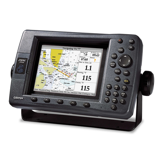
Garmin GPSMAP 17 Installation Instructions Manual
Marine gps navigation system
Hide thumbs
Also See for GPSMAP 17:
- Quick start manual (16 pages) ,
- Installation manual (16 pages) ,
- Technical specifications (40 pages)
Table of Contents
Advertisement
Quick Links
Advertisement
Table of Contents

Related Manuals for Garmin GPSMAP 17


Summary of Contents for Garmin GPSMAP 17
- Page 1 GPSMAP ® 2006/2010 & GPS 17 installation instructions...
-
Page 2: Safety Information
Limited Warranty This Garmin product is warranted to be free from defects in materials or workmanship for one year from the date of purchase. Within this period, Garmin will at its sole option repair or replace any components that fail in normal use. Such repairs or replacement will be made at no charge to the customer for parts or labor, provided that the customer shall be responsible for any transportation cost. - Page 3 When drilling or cutting, always check first to see what is on the opposite side of the surface. Mount the GPSMAP 2006C/2010C in a location that provides a clear, glare-free view of the display and easy operation of the controls. If you experience difficulty installing the unit, contact Garmin Product Support or seek the assistance of a professional installer. Mounting Knob...
-
Page 4: Installation Instructions
NSTALLATION NSTRUCTIONS Surface Mount Tools • Drill and Drill Bit • Screwdriver • Pencil • Mounting Hardware (not included) NOTE: Mounting hardware (fasteners) not included. Mounting holes are 5/16" (7.9 mm) in diameter. To install the Bail Mount and unit: 1. -
Page 5: Flush Mount
Flush Mount Tools • Flush Mount Template • Jig saw • Masking tape • Scissors • Drill • Drill bits—1/8" (3 mm) and 3/8" (6 mm) • 1/16" (2 mm) Allen (Hex) wrench • Sockets or wrenches • Hammer • Center punch To flush mount the GPSMAP 2006C/2010C: 1. -
Page 6: Installing The Gps
NSTALLATION NSTRUCTIONS Installing the GPS 17 The GPS 17 can be flush mounted or installed on any standard 1" O.D. (Outer Dimension), 14 threads-per-inch marine mount. When mounting the GPS 17, the cable can be run externally or through the mounting panel or through the center of the marine mount. - Page 7 To attach the enclosed pole mount to the GPS 17: 1. Thread the cable though the pole mount. 2. Align the tab on the mount to the notch on the GPS 17. 3. Use the enclosed screws to secure the mount to the base. Attaching the Pole Mount to the GPS 17 Align notch GPSMAP 2006C/2010C &...
- Page 8 TO SELECT BETWEEN VISUAL AND AUDIBLE ALERTS, IF REQUIRED WIRE 18 AWG SHIP'S BATTERY 10-32 VOLTS ALARM SEE NOTE 18 AWG Diagram 1 - Basic Hook-up GARMIN GPS 17 GPS SENSOR WIRE COLOR YELLOW POWER BLACK GROUND COM 1 IN...
- Page 9 SOUNDER MODULE (SEE GSD 20 INSTALL INSTRUCTIONS) 4. A GARMIN SOUNDER UNIT (OTHER THAN GSD 20) CAN PROVIDE WATER DEPTH, WATER TEMPATURE, AND SPEED VIA NMEA DATA FOR DISPLAY ON THE GPSMAP 2006/2010. Diagram 2 - Complete Interface GPSMAP 2006C/2010C & GPS 17...
- Page 10 NSTALLATION NSTRUCTIONS Final Wiring Connection Once all the wiring is complete, plug the 18-pin harness into the center connector on the backside of the GPSMAP 2006/2010. The 5-pin port on the right side is intended for future interfacing features and does not require connection at this time. With power applied to the circuit, you may test the installation by pressing the POWER key on the front of the unit.
- Page 11 NSTALLATION NSTRUCTIONS LUSH OUNT RILLING EMPLATE Drill using a 11/64” or 4.5 mm drill bit Dill this 3/4” or 19 mm hole if the coax is going to be installed through the mounting panel GPSMAP 2006C/2010C & GPS 17...
- Page 12 © Copyright 2005 Garmin Ltd. or its subsidiaries Garmin International, Inc. 1200 East 151 Street, Olathe, Kansas 66062, U.S.A. Garmin (Europe) Ltd. Unit 5, The Quadrangle, Abbey Park Industrial Estate, Romsey, SO51 9DL, U.K. Garmin Corporation No. 68, Jangshu 2 Road, Shijr, Taipei County, Taiwan www.garmin.com...