Garmin GPSMAP 3006C Installation Instructions Manual
Garmin gpsmap 3006c: installation instruction
Hide thumbs
Also See for GPSMAP 3006C:
- Installation instructions manual (16 pages) ,
- Installation instructions manual (17 pages) ,
- Technical specifications (37 pages)
Advertisement
Advertisement
Table of Contents

Related Manuals for Garmin GPSMAP 3006C


Summary of Contents for Garmin GPSMAP 3006C
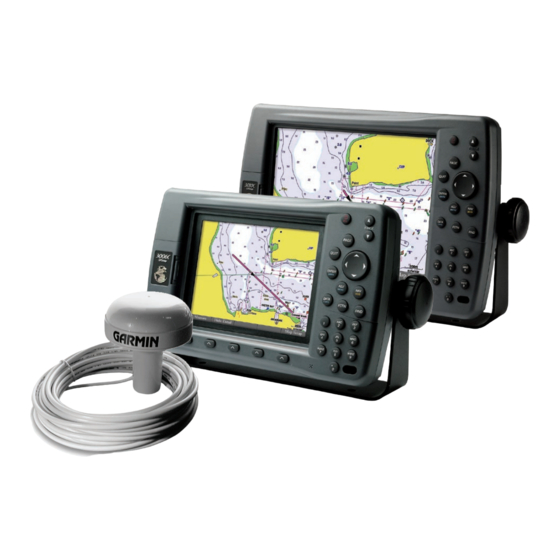
- Page 1 GPSMAP ® 3006C/3010C & GPS 17 installation instructions...
-
Page 2: Safety Information
Limited Warranty This Garmin product is warranted to be free from defects in materials or workmanship for one year from the date of purchase. Within this period, Garmin will at its sole option repair or replace any components that fail in normal use. Such repairs or replacement will be made at no charge to the customer for parts or labor, provided that the customer shall be responsible for any transportation cost. - Page 3 Always wear safety goggles, ear protection, and a dust mask when drilling, cutting, or sanding. When drilling or cutting, always check first to see what is on the opposite side of the surface. Mount the GPSMAP 3006C/3010C in a location that provides a clear, glare-free view of the display and easy operation of the controls.
-
Page 4: Installation
NSTALLATION NSTRUCTIONS Surface Mounting the GPSMAP 3006C/3010C Tools • Drill and drill bit • Screwdriver • Pencil • Mounting hardware (not included) NOTE: Mounting hardware (fasteners) not included. Mounting holes are 5/16" (7.9 mm) in diameter. To install the Bail Mount and unit: 1. -
Page 5: Installation Instructions
• Sockets or wrenches • Hammer • Center punch To flush mount the GPSMAP 3006C/3010C: 1. Trim the Flush Mount Template, and tape it in the location you want. 2. Using the center punch, indent the center of each mounting hole location. -
Page 6: Installing The Gps
3. Drill the holes using the appropriate drill bits. 4. Align the GPS 17 over the mounting holes, and fasten it using M4 screws. The mounting threads in the GPS 17 are 8.10 mm deep. Do not use screws that thread into the GPS 17 deeper than 8 mm, or the case may be damaged. - Page 7 To attach the enclosed pole mount to the GPS 17: 1. Thread the cable though the pole mount. 2. Align the tab on the mount to the notch on the GPS 17. 3. Use the enclosed screws to secure the mount to the base.
-
Page 8: Wiring And Cables
The GPSMAP 3006C/3010C comes with an 18-pin Power/NMEA and a 17-pin Marine Video cable. Optional Garmin Marine Network components use specialized Garmin Network cables. For some installations, it may be necessary to drill 1.25" (31.7 mm) holes to route the connector end of the cables. -
Page 9: Power/Data Cable Wiring
The following pages contain several wiring diagrams. The first diagram on the next page shows the GPSMAP 3006C/3010C MFD using the 18-pin Power/Data wiring harness and the GPS 17. If two or more GPSMAP 3006C/3010C units are installed and networked, only one GPS 17 antenna needs to be installed. -
Page 10: Garmin Wiring Diagram
BLUE (DATA IN) � � ���� ������ ���� ����� ������� ��� ����� ���� ��� � � ���� ������� ��������� ������ ����� � ���� ������ �� ���������� ���� ��� ������� � � � � � � � � GPSMAP 3006C/3010C & GPS 17... - Page 11 Optional Alarm Wiring The GPSMAP 3006C/3010C has an alarm circuit that can be used with a lamp, a horn, or both to alert you when the unit displays a message. The alarm circuit pulls low when the alarm sounds. The alarm does not have to be wired for the unit to function. The maximum current is 100 milliamps.
- Page 12 VCR, DVD, TV, or a video camera. The MFD can display one video input at a time or alternate between the two (see the GPSMAP 3006C/3010C Owner’s Manual). Sound from a video source must be attached to a separate stereo/audio system. The video output from video device attaches to the Video 1 (Black Cable) or Video 2 (Gray Cable) RCA connectors.
-
Page 13: Garmin Marine Network
MFDs over the network. Waterproof RJ-45 connections allow for simple installation and high-speed connectivity. For a simple installation with one MFD and one sensor, the two devices can be directly connected with a Garmin Marine Network cable. If more than two MFDs are installed, you need a Garmin Marine Network Port Expander (GMS 10) to expand the network. - Page 14 NSTALLATION NSTRUCTIONS The following diagram shows the Garmin Marine Network with a GSD Sounder Module connected. NOTE: Power connections for network components are not shown in the following illustrations. GARMIN MARINE RADAR GARMIN GDL 30/30A MARINE WEATHER/AUDIO SATELLITE RECEIVER GPS 17...
- Page 15 Final Wiring Connection After all the wiring is complete, the cables are attached on the back of the GPSMAP 3006C/3010C MFD. If the MFD is not being networked, be sure to firmly affix the weather cap over the open connector to limit corrosion of the contacts. The connection ports are labeled on the back of the MFD.
- Page 16 NSTALLATION NSTRUCTIONS GPSMAP 3006C/3010C & GPS 17...
- Page 17 NSTALLATION NSTRUCTIONS Flush Mount Drilling Template Drill using a 11/64" (4.5 mm) drill bit Drill this 3/4" (19 mm) hole if the coax is going to be installed through the mounting panel. GPSMAP 3006C/3010C & GPS 17...
- Page 18 © Copyright 2004, 2005, 2006 Garmin Ltd. or its subsidiaries Garmin International, Inc. 1200 East 151 Street, Olathe, Kansas 66062, U.S.A. Garmin (Europe) Ltd. Unit 5, The Quadrangle, Abbey Park Industrial Estate, Romsey, SO51 9DL, U.K. Garmin Corporation No. 68, Jangshu 2 Road, Shijr, Taipei County, Taiwan www.garmin.com...