Garmin GPS 17 Installation Manual
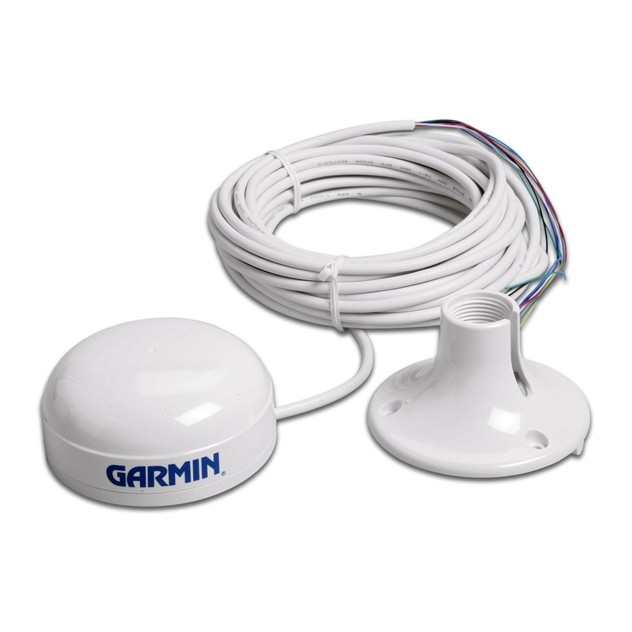
Gps receiver/antenna
Hide thumbs
Also See for GPS 17:
- Quick start manual (16 pages) ,
- Installation instructions manual (12 pages) ,
- Technical specifications (40 pages)
Table of Contents
Advertisement
Advertisement
Table of Contents

Related Manuals for Garmin GPS 17


Summary of Contents for Garmin GPS 17
- Page 1 GPS 17 GPS receiver/antenna installation guide...
- Page 2 Information in this document is subject to change without notice. Garmin reserves the right to change or improve its products and to make changes in the content without obligation to notify any person or organization of such changes or improvements.
-
Page 3: Table Of Contents
Serial Number: ____ ____ ____ ____ ____ ____ ____ ____ Contact Information If you should encounter any difficulty while using your GPS 17, or if you have any questions, in the U.S.A. contact Garmin Support by phone: 913/397.8200 or 800/800.1020, Monday–Friday, 8 AM–5 PM Central Time;... -
Page 4: Introduction
Failure to avoid the following potentially hazardous situations may result in injury or property damage. Use the GPS 17 only as a navigational aid. Do not attempt to use the GPS 17 for any purpose requiring precise measurement of direction, distance, location, or topography. This product should not be used to determine ground proximity for aircraft navigation. -
Page 5: Specifications
Physical Characteristics Size: 3.58” (91.0 mm) diameter, 3.60” (91.5 mm) high Weight: GPS 17 only: 7.1 oz (201 g) With 30 foot cable: 16.8 oz (465 g) With pole mount adapter & cable: 18.2 oz (516 grams) Pole mount adapter alone: 1.4 oz (40 grams) Cable alone: 9.7 oz (275 g) -
Page 6: Mounting The Receiver
When in doubt, seek professional assistance. You can use an antenna mount to install the GPS 17. The receiver base fits a standard 1-inch, 14 threads-per-inch marine mount. Check with your Garmin dealer or a marine retailer for a suitable mount for the installation location. -
Page 7: Mounting Location Tips
(metal, aluminum, etc.) as this may cause poor signal reception. • Do not mount the GPS 17 high on a mast, as the top of the mast travels more than the boat. The unit will provide more stable readings if it is located near the water level. - Page 8 1. Place the cable in the vertical slot along the side of the base of the unit. 2. Screw the GPS 17 onto the mount. Do not overtighten: it is possible to tighten the unit to the point that the cable may be cut in two.
-
Page 9: Routing The Cable
To mount the GPS 17 with cable through mount: 1. Position the mount in the desire location and mark the approximate center of the mount 2. Drill a hole large enough for the cable to pass through at the marked location. -
Page 10: Wiring The Gps 17
IRING THE After mounting the GPS 17 in the desired location, connect the wiring. Connect the GPS 17’s Port 1 Data In, Data Out, Remote On/Off, and Ground (Return) lines to your NMEA device or PC. Port 2 is used for RTCM input only. -
Page 11: Wiring Diagrams
GPS 17 Installation Guide Power Source 8–40 Volts DC Power Ground Data Out > Data In > Figure 5: NMEA and GPS 17 Wiring Power Source 8–40 Volts DC Fuse Red (Power) Black (Ground) Yellow (On/Off) Switch Figure 6: GPS 17 Switch Wiring... - Page 12 White: Remote On/Off Brown: Data In White (Port 1 Data Out) Blue: Data Out Green (Port 2 Data In) Figure 7: DGPS GBR 21/23 and GPS 17 Wiring Power Source 8–40 Volts DC Red (Power) Pin 5: Ground Black (Ground)
- Page 13 To wire the GPS 17 to a NMEA Device or PC Connector: 1. Connect the White (Port 1 Data Out) wire from the GPS 17’s power/data cable to the DATA INPUT line of the NMEA device or to pin 2 on a DB-9 (pin 3 on DB-25).
-
Page 14: Using The Gps 17
GPS 17 SING THE First Time Fix The first time you turn on your GPS 17, the receiver must be given an opportunity to collect satellite data and determine its present position. To ensure proper initialization, the GPS 17 is shipped from the factory in AutoLocate allows the receiver to “find itself”... -
Page 15: Limited Warranty
® or workmanship for one year from the date of purchase. Within this period, Garmin will at its sole option repair or replace any components that fail in normal use. Such repairs or replacement will be made at no charge to the customer for parts or labor, provided that the customer shall be responsible for any transportation cost. - Page 16 For the latest free software updates (excluding map data) throughout the life of your Garmin products, visit the Garmin Web site at www.garmin.com. © Copyright 2005 Garmin Ltd. or its subsidiaries Garmin International, Inc. 1200 East 151 Street, Olathe, Kansas 66062, U.S.A.