Table of Contents
Advertisement
Quick Links
Advertisement
Table of Contents

Related Manuals for Yamaha 6Y8- 2819U-00


Summary of Contents for Yamaha 6Y8- 2819U-00
- Page 1 COMMAND LINK MULTIFUNCTION METER (SQUARE) OPERATION MANUAL 6Y8-2819U-00...
- Page 2 To the owner COMMAND LINK Thank you for choosing the Yamaha Com- MULTIFUNCTION METER mand Link Multifunction Meter. (SQUARE) OPERATION MANUAL This Operation Manual contains information ©2005 by Yamaha Motor Co., Ltd. you will need for proper operation. 1st Edition, March 2005 A thorough understanding of these simple All rights reserved.
-
Page 3: Button Operations
The Command Link Multifunction Meter The operations of the SET button and the enables the display of information through MODE button are described in this manual digital communication with the engine. as follows. Optional parts such as the speed sensor, Button operations: cooling water pressure sensor, Triducer- •... -
Page 4: Table Of Contents
Table of contents 1. Tachometer unit ....... 1 2. Speedometer unit....22 Description ........2 Description ........ 23 Activating the meter ....2 Activating the meter ....23 Periodic maintenance Speedometer ......24 notification ......3 Fuel meter......... 25 Tachometer ......... 3 Multifunction display.... - Page 5 Table of contents Changing settings UNIT (setting displayed (custom mode) ....... 41 units) ........59 Switching to custom mode ..41 FUEL SENSOR Resetting custom mode ..41 (setting fuel sensor) .... 61 DISPLAY (setting displays) ..42 CALIBRATION UNIT (setting displayed (setting correction value) ..
-
Page 6: Tachometer Unit
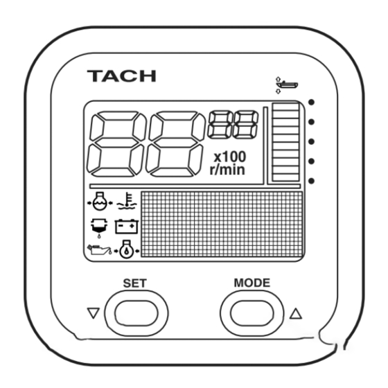
1. Tachometer unit NOTE: Depending on the model of the outboard motor, some functions may not be compatible. For information on models which contain the compatible functions, consult a Yamaha dealer. Tachometer Trim meter The tachometer The trim meter shows... -
Page 7: Description
Description/Activating the meter Description Activating the meter When the engine start switch is turned to ON, the meter is activated and “Welcome” appears on the multifunction meter. Then, all the displays come on and the display switches to the normal display after the total hour display comes on. -
Page 8: Periodic Maintenance Notification
• When the hours of engine operation exceed 100 hours and the periodic main- tenance notification is activated, consult an authorized Yamaha dealer for periodi- cal maintenance. When the angle of the outboard motor • To reset the maintenance period, see exceeds the trim range, the top segment “MAINTENANCE (resetting maintenance... -
Page 9: Multifunction Display
Multifunction display Multifunction display When the engine start switch is turned to The multifunction display shows up to three OFF, the last display shown is shown first types of information simultaneously using when the engine start switch is turned to ON numeric values or graphics. -
Page 10: Oil Pressure Display (4-Stroke Models)
• Do not operate the engine without engine oil. Severe engine damage can result. • Check the oil level by following the procedure described in the engine Owner’s Manual. • If you cannot locate and correct the cause, consult a Yamaha dealer. -
Page 11: Oil Level Display (2-Stroke Models)
Oil level display (2-stroke models)/Total hour, Trip hour display Oil level display (2-stroke models) Total hour, Trip hour display The oil level indicator ( ) comes on and The total hour display shows the total hours the engine oil level is shown in 3 levels. of engine operation and the trip hour display shows the trip hours (Tr). -
Page 12: Cooling Water/Engine Temperature Display
“OVERHEAT” warning blink. Blink CAUTION: • When the overheat warning comes on, turn the engine off and check the cool- ing water inlet for clogs. • If you cannot locate and correct the cause, consult a Yamaha dealer. -
Page 13: Battery Voltage Display
16 volts or more wiring. the battery voltage indicator ( ) and the • If you cannot locate and correct the voltage value blink. cause, consult a Yamaha dealer. NOTE: The voltage level display shows “L” for low and “H” for high. Blink... -
Page 14: Cooling Water Pressure Display (Optional: Cooling Water Pressure Sensor Has Been Installed)
• If you cannot locate and correct the cause, consult a Yamaha dealer. NOTE: The cooling water pressure level display shows “L” for low and “H” for high. -
Page 15: Changing Backlight Settings
Changing backlight settings/Adjusting trolling speed Changing backlight settings Adjusting trolling speed You can turn the backlight on or off, or You can adjust the trolling speed randomly change the brightness level of the backlight by increasing or decreasing it approximately for all meters synchronized. -
Page 16: Changing Settings (Custom Mode)
• Depending on the model of the outboard motor, some functions may not be com- patible. For information on models which contain the compatible functions, consult a Yamaha dealer. : Press to switch between the set- ting function names (custom mode selection display). -
Page 17: Resetting Custom Mode
MAINTENANCE (resetting maintenance intervals) Change the various settings and return MAINTENANCE (resetting maintenance to the custom mode selection display. intervals) To change the settings, see the corre- You can reset the elapsed time from the sponding sections for each setting func- previous maintenance interval (when the tion. -
Page 18: Trim Set (Setting Trim Angle)
TRIM 0SET (setting trim angle)/DISPLAY (setting displays) TRIM 0SET (setting trim angle) DISPLAY (setting displays) You can set the trim angle to zero. Fully trim You can change the display configuration of the outboard motor down. the normal display. There are a total of 16 Turn the engine off and the engine start combinations of which up to four displays switch to ON. - Page 19 DISPLAY (setting displays) * In the display example, display number 01 (4 seconds): To activate the cus- and display configuration number 13 are tom mode. shown. times): Press switch between the setting function names. : To switch to the change settings display.
-
Page 20: Form (Setting Display Format)
FORM (setting display format) FORM (setting display format) (1 second): To reset the You can change the display formats of the display configuration default settings total hour and trip hour (Tr) display, the bat- and return to the custom mode selec- tery voltage display and the cooling water tion display. - Page 21 FORM (setting display format) One display: Display configuration number (1 second): To return to the nor- (16) mal display. Total hour + Trip hour (Tr) Battery voltage: Turn the engine off and the engine start Total hour switch to ON. (4 seconds): To activate the cus- Trip hour (Tr) tom mode.
- Page 22 FORM (setting display format) Cooling water pressure: Turn the engine off and the engine start switch to ON. (4 seconds): To activate the cus- tom mode. times): Press switch Blink between the setting function names. : To switch to the change settings display.
- Page 23 FORM (setting display format) Blink Blink * In the display example, the cooling water * In the display example, the cooling water pressure level (with scale) is shown. pressure level (with scale) and the oil level display are shown. Two displays: Display configuration number (06) Two displays: Display configuration number (08)
-
Page 24: Engine Number (Setting Corresponding Engine)
ENGINE NUMBER (setting corresponding engine) ENGINE NUMBER (setting (1 second): To return to the nor- corresponding engine) mal display. You can select the engines that are compat- NOTE: ible to this meter. The port outboard motor is • The meters are set at the factory to “No.1 set to “No.1 (engine number 1)”... -
Page 25: Service Functions
You can display the self-diagnosis results of When a diagnosis code other than “01” the engine. is displayed, the engine cannot be oper- ated normally. Consult a Yamaha dealer. (10 seconds): To scroll “DIAGNOSIS” and to display the diagnosis codes. NOTE: When there are no malfunctions, the “01”... -
Page 26: Resetting Engine Number
Service functions Resetting engine number When replacing the engines of multiple out- board motors or resetting the setting order, reset all engine numbers to “No. 1 (engine number 1).” Turn the engine off and the engine start switch to ON. seconds): “ENGINE RESET”... -
Page 27: Speedometer Unit
2. Speedometer unit NOTE: Depending on the model of the outboard motor, some functions may not be compatible. For information on models which contain the compatible functions, consult a Yamaha dealer. Speedometer Fuel meter Shows the speed of The fuel meter shows the boat. -
Page 28: Description
Description/Activating the meter Description Activating the meter When the engine start switch is turned to ON, the meter is activated and “Welcome” appears on the multifunction meter. Then, all the displays come on and the display switches to the normal display after a few seconds. -
Page 29: Speedometer
Speedometer Speedometer NOTE: The speedometer shows the ground speed • If no operations are carried out for 30 sec- or the water speed of the boat. To display onds or more, the speed sensor is set and the ground speed, the GPS must be con- the display returns to the normal display. -
Page 30: Fuel Meter
Fuel meter/Multifunction display Fuel meter Multifunction display The fuel meter shows the remaining fuel The multifunction display shows up to two level in 10 levels and all the segments are types of information simultaneously using displayed when the fuel tank is full. When numeric values. -
Page 31: Trip Display (Optional: Speed Sensor Has Been Installed)
Trip display Trip display (optional: speed sensor has NOTE: been installed) • Since “Display 1” is the only default dis- TRIP shows the information from the speed play, no displays can be switched. sensor converted to the distance traveled. • To change the display configuration, see “DISPLAY (setting displays)”... -
Page 32: Ambient Water Temperature Display (Optional: Triducer-Multi Sensor Has Been Installed)
Ambient water temperature display/Depth display Ambient water temperature display Depth display (optional: Triducer-multi (optional: Triducer-multi sensor has sensor has been installed) been installed) DEPTH or DPTH shows the water depth. TEMP shows the ambient water tempera- ture. NOTE: You can select to show feet (F) or meters NOTE: (m) on the DEPTH or DPTH display. -
Page 33: System Voltage Display
(1 second): To reset the wiring. time to “0:00” and return to the normal • If you cannot locate and correct the display. cause, consult a Yamaha dealer. -
Page 34: Changing Backlight Settings
Changing backlight settings/Changing settings (custom mode) Changing backlight settings Changing settings (custom mode) You can turn the backlight on or off, or Switching to custom mode change the brightness level of the backlight In the custom mode, you can change the for all meters collectively. -
Page 35: Resetting Custom Mode
DISPLAY (setting displays) DISPLAY (setting displays) NOTE: You can change the display configuration of • If no operations are carried out for 30 sec- the normal display. There are a total of 15 onds or more or if the engine is started, combinations of which up to four displays the settings will not be applied and the can be set up. - Page 36 DISPLAY (setting displays) : To switch to the change settings display. : Press to switch between the dis- play numbers. Select the display num- ber (1–4) you want to change. The first two digits in the speedometer display show the display numbers. * When the display configuration number 0 is selected, “HIDDEN”...
-
Page 37: Unit (Setting Displayed Units)
UNIT (setting displayed units) UNIT (setting displayed units) TEMP You can change the units that are shown in You can select to show Fahrenheit (°F) or each display. Celsius (°C). Turn the engine off and the engine start The default setting is Fahrenheit (°F). switch to ON. -
Page 38: Fuel Sensor (Setting Fuel Sensor)
: To switch to the change settings display. : Press to switch between the fuel sensor types. ABYC (US) EUROPE YAMAHA Blinks (1 second): To change the fuel sensor type and return to the custom mode selection display. (1 second): To return to the nor-... -
Page 39: Fuel Management Meter Unit
3. Fuel management meter unit NOTE: Depending on the model of the outboard motor, some functions may not be compatible. For information on models which contain the compatible functions, consult a Yamaha dealer. Fuel flow meter The fuel flow meter... -
Page 40: Description
Description/Activating the meter Description Activating the meter When the engine start switch is turned to ON, the meter is activated and “Welcome” appears on the multifunction meter. Then, all the displays come on and the display switches to the normal display after a few seconds. -
Page 41: Fuel Flow Meter
Fuel flow meter Fuel flow meter When two outboard motors are installed: The fuel flow meter shows the fuel economy PS (port & starboard) of each engine or the total fuel consumption per hour of all engines. P (port) When multiple outboard motors... -
Page 42: Multifunction Display
Multifunction display Multifunction display The multifunction display shows up to two types of information simultaneously using numeric values. In addition, up to three dis- plays can be set up for the display configu- ration with a combination of information. The configuration of the default displays is described below. -
Page 43: Total Fuel Consumption Display
Total fuel consumption display Total fuel consumption display NOTE: TTL shows the total fuel consumption of all • Since “Display 1” is the only default dis- engines. play, no displays can be switched. • To change the display configuration, see “DISPLAY (setting displays)”... -
Page 44: Fuel Economy Display
Fuel economy display Resetting the TTL (total fuel consumption) Fuel economy display and AVAL (available: remaining fuel) dis- ECON shows the distance traveled per unit plays: of fuel. Be sure to reset the TTL display on a full tank of fuel. If the TTL display is reset when the fuel tank is not full or if not reset and the fuel tank is filled with fuel, the AVAL display will not be displayed accurately. -
Page 45: Remaining Fuel Display
Remaining fuel display/Changing backlight settings Remaining fuel display (1 second) or AVAL shows the numeric value of the con- (1 second): To simultaneously reset the sumed fuel that is deducted from 90 percent AVAL and TTL displays and return to of the specified fuel tank capacity. -
Page 46: Changing Settings
Changing settings (custom mode) Changing settings (custom mode) (1 second): To return to the nor- Switching to custom mode mal displays. In the custom mode, you can change the NOTE: meter function settings. “CUSTOM” and • If no operations are carried out for 30 sec- each setting function name are scrolled on onds or more or if the engine is started, the meter. -
Page 47: Display (Setting Displays)
DISPLAY (setting displays) DISPLAY (setting displays) You can change the display configuration of the normal display. There are a total of 6 combinations of which up to three displays can be set up. The display configuration number that has been selected as the default display config- uration indicated shaded... -
Page 48: Unit (Setting Displayed Units)
UNIT (setting displayed units) * When the display configuration number UNIT (setting displayed units) “0” is selected, “HIDDEN” is shown and You can change the units that are shown in the display is not shown. each display. Turn the engine off and the engine start (1 second): To change the display switch to ON. -
Page 49: (Setting Fuel Tank Capacity)
TANK CAPA. (setting fuel tank capacity) TANK CAPA. (setting fuel tank capacity) You can select to show gallons (G) or liters You can set the capacity of the fuel tank that (L). is connected to this meter. The default setting is gallons (G). Turn the engine off and the engine start ECON switch to ON. -
Page 50: Calibration (Setting Correction Value)
CALIBRATION (setting correction value) CALIBRATION (setting correction value) NOTE: You can calibrate the displayed fuel flow • The default setting of the fuel tank capac- value within –7 to +7 percent. The difference ity is 50 G (190 L). The maximum fuel tank in the fuel consumption display and the capacity can be set to 1,999 gallons or actual fuel consumption is calibrated. - Page 51 CALIBRATION (setting correction value) (1 second): To return to the nor- mal display. NOTE: • The fuel flow display may differ depending on the operating conditions. • When the fuel flow calibration value is changed, the fuel flow meter, TTL, ECON, and AVAL displays are shown calibrated.
-
Page 52: Speed & Fuel Meter Unit
4. Speed & Fuel meter unit NOTE: Depending on the model of the outboard motor, some functions may not be compatible. For information on models which contain the compatible functions, consult a Yamaha dealer. Speedometer Fuel meter Shows the speed of The fuel meter shows the boat. -
Page 53: Description
Description/Activating the meter Description Activating the meter When the engine start switch is turned to ON, the meter is activated and “Welcome” appears on the multifunction meter. Then, all the displays come on and the display switches to the normal display after a few seconds. -
Page 54: Speedometer
Speedometer Speedometer NOTE: The speedometer shows the ground speed • If no operations are carried out for 30 sec- or the water speed of the boat. To display onds or more, the speed sensor is set and the ground speed, the GPS must be con- the display returns to the normal display. -
Page 55: Fuel Meter
Fuel meter/Multifunction display Fuel meter Multifunction display The fuel meter shows the remaining fuel The multifunction display shows up to two level in 10 levels and all segments are dis- types of information simultaneously using played when the fuel tank is full. When the numeric values. -
Page 56: Trip Display (Optional: Speed Sensor Has Been Installed)
Trip display When the engine start switch is turned to Trip display (optional: speed sensor has OFF, the last display shown is shown first been installed) when the engine start switch is turned to ON TRIP shows the information from the speed again. -
Page 57: Fuel Economy Display
Fuel economy display/Fuel flow display Fuel economy display Fuel flow display ECON shows the distance traveled per unit FLOW shows the total fuel consumption per of fuel. hour of all engines. NOTE: NOTE: • Fuel economy is affected by the type of You can select to show gallons per hour boat being operated and the operating (GPH) or liters per hour (l/h) on the FLOW... -
Page 58: Total Fuel Consumption Display
Total fuel consumption display/Ambient water temperature display Total fuel consumption display Ambient water temperature display TTL shows the total fuel consumption of all (optional: Triducer-multi sensor has engines. been installed) TEMP shows the ambient water tempera- ture. The TTL display cannot measure over 1,999 gallons or 1,999 liters. -
Page 59: Depth Display (Optional: Triducer-Multi Sensor Has Been Installed)
16 volts or more (custom mode).” the voltage value blinks. Blinks CAUTION: • When the low battery voltage warning comes on, check the battery and the wiring. • If you cannot locate and correct the cause, consult a Yamaha dealer. -
Page 60: Clock (Optional: Gps Has Been Installed)
Clock/Changing backlight settings Clock (optional: GPS has been installed) Changing backlight settings The clock shows the time in 12 hours. The You can turn the backlight on or off, or local time is easily displayed by calculating change the brightness level of the backlight the longitude information received from the for all meters collectively. -
Page 61: Changing Settings (Custom Mode)
Changing settings (custom mode) Changing settings (custom mode) (1 second): To return to the nor- Switching to custom mode mal display. In the custom mode, you can change the NOTE: meter function settings. “CUSTOM” and • If no operations are carried out for 30 sec- each setting function name are scrolled on onds or more or if the engine is started, the meter. -
Page 62: Display (Setting Displays)
DISPLAY (setting displays) DISPLAY (setting displays) You can change the display configuration of the normal display. There are a total of 36 combinations of which up to five displays can be set up. The display configuration numbers that have been selected as the default display config- uration are indicated by the shaded areas —... - Page 63 DISPLAY (setting displays) Changing the display configurations: * In the display example, the display num- Turn the engine off and the engine start ber 3 and the display configuration num- switch to ON. ber 36 are shown. (4 seconds): To activate the cus- tom mode.
-
Page 64: Unit (Setting Displayed Units)
UNIT (setting displayed units) UNIT (setting displayed units) (1 second): To return to the nor- You can change the units that are shown in mal display. each display. Turn the engine off and the engine start switch to ON. (4 seconds): To activate the cus- tom mode. - Page 65 UNIT (setting displayed units) : Press to switch between the dis- NOTE: played units. When the speedometer unit settings are changed, the TRIP, FLOW, ECON, TTL, Speedometer TEMP, and DPTH settings can be collec- You can select to show miles per hour tively changed automatically.
-
Page 66: Fuel Sensor (Setting Fuel Sensor)
Changing the calibration value: ABYC (US) Turn the engine off and the engine switch to ON. EUROPE (4 seconds): To activate the cus- YAMAHA tom mode. times): Press switch between the setting function names. : To switch to the change settings display. - Page 67 CALIBRATION (setting correction value) (1 second): To return to the nor- mal display. NOTE: • The fuel flow display may differ depending on the operating conditions. • When the fuel flow calibration value is changed, the FLOW, TTL, and ECON dis- plays are shown calibrated.
-
Page 68: Setting Up The Meters
Activating for the first time 5. Setting up the meters Activating for the first time After installing the meters, be sure to turn To install the meters and the optional sen- the engine start switch to ON when the sors and to connect the meters to the power is supplied for the first time. -
Page 69: Setting The Initial Settings
Setting the initial settings Setting the initial settings DISPLAY (setting displays) Before operating the meter, be sure to Change the display configuration number as change the default settings as described necessary so that the AVAL display can be below. For the setting procedures, see the displayed. - Page 72 YAMAHA MOTOR CO., LTD. Printed in Japan March 2005 – 1.5 × 1 CR Printed on recycled paper...