Table of Contents
Advertisement
This .pdf document is bookmarked
Operating Instructions and Parts Manual
10" Job Site Table Saw
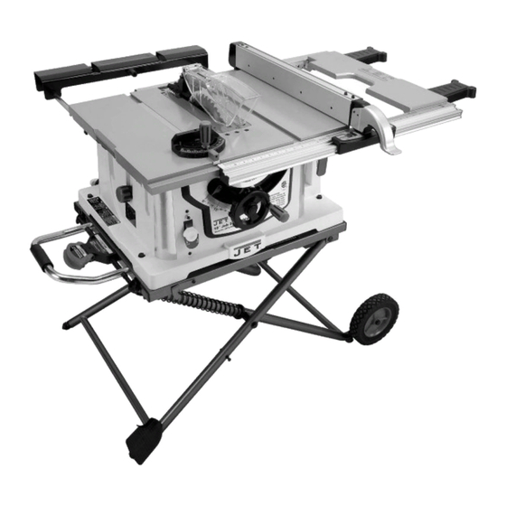
Benchtop Series – Model No. JBTS-10MJS
R
C
US
174315
WALTER MEIER (Manufacturing) Inc.
427 New Sanford Road
LaVergne, Tennessee 37086
Part No. M-707000
Ph.: 800-274-6848
Revision A3 10/2010
www.waltermeier.com
Copyright © 2010 Walter Meier (Manufacturing) Inc.
Advertisement
Table of Contents

Related Manuals for Jet JBTS-10MJS


Summary of Contents for Jet JBTS-10MJS
- Page 1 This .pdf document is bookmarked Operating Instructions and Parts Manual 10" Job Site Table Saw Benchtop Series – Model No. JBTS-10MJS 174315 WALTER MEIER (Manufacturing) Inc. 427 New Sanford Road LaVergne, Tennessee 37086 Part No. M-707000 Ph.: 800-274-6848 Revision A3 10/2010 www.waltermeier.com...
-
Page 2: Warranty And Service
Walter Meier is consistently adding new products to the line. For complete, up-to-date product information, check with your local Walter Meier distributor, or visit waltermeier.com. WARRANTY JET products carry a limited warranty which varies in duration based upon the product (MW stands for Metalworking, WW stands for Woodworking). WHAT IS COVERED? This warranty covers any defects in workmanship or materials subject to the exceptions stated below. -
Page 3: Table Of Contents
Table of Contents Warranty and Service..........................2 Table of Contents .............................3 Warnings..............................4 Table Saw Safety .............................6 Specifications ............................7 Definitions and Terminology ........................7 Electrical ..............................8 Grounding Instructions ...........................8 115 Volt Operation Only .........................8 Extension Cords ............................8 Features ..............................9 Shipping Contents ..........................10 Assembly ............................... -
Page 4: Warnings
Warnings 1. Read and understand the entire owners' manual before attempting assembly or operation. 2. Read and understand the warnings posted on the machine and in this manual. Failure to comply with all of these warnings may cause serious injury. 3. - Page 5 20. Don't use in dangerous environment. Don't use power tools in damp or wet locations, or expose them to rain. Keep work area well lighted. 21. Keep visitors a safe distance from the work area. Keep children away. 22. Make your workshop child proof with padlocks, master switches or by removing starter keys. 23.
-
Page 6: Table Saw Safety
Table Saw Safety 1. Always use a saw blade guard, splitter and anti-kickback pawls for every through–sawing operation. Through–sawing operations are those in which the blade cuts completely through the workpiece when ripping or crosscutting. Always be sure the blade guard is tightened securely. 2. -
Page 7: Specifications
Specifications Stock Number .......................... 707000 Motor ....................120VAC, 1PH, 60Hz, 15A, 4.4HP Blade Speed - no load (RPM) ......................4000 Saw Blade Diameter (in.)........................10 Arbor Diameter (in.) ......................... 5/8 Blade Tilt (deg.) ...........................45 left Rip Capacity (in.) ..........................25 Maximum Cutting Depth at 90º... -
Page 8: Electrical
Electrical Grounding Instructions In the event of a malfunction or breakdown, grounding provides a path of least resistance for electric current to reduce the risk of electric shock. This tool is equipped with an electric cord having an equipment-grounding conductor and a grounding plug. -
Page 9: Features
Features Figure 1 – Features... -
Page 10: Shipping Contents
Make certain that all items are accounted for before discarding any packing material. Report any shortages or damage to your JET distributor. Contents of the Shipping Container (These items shown in Figure 3) Blade Guard (1) - Page 11 Figure 4 – Hardware Hardware The following items are shown in Figure 4. aZ oStand Pad (1) Q Screw (2) AA oSplitter/Riving Knife Lock Knob (1) Collar (4) BB oFlat Washer (1) Shaft Sleeve (2) CC oSplitter/Riving Knife Plate (1) Nut (2) DD oHandwheel Handle (1) Screw (1)
-
Page 12: Assembly
Assembly Note: The letter designators used in the assembly section are the same as those used in the shipping contents and hardware section (page 10-11) for the purpose of simplifying part identification. Stand Stand may pop up unexpectedly without weight of saw on stand. In order to avoid injury, verify that the lock hook (G , Fig. -
Page 13: Mounting The Saw To Work Surface
Mounting the Saw to Work Surface A hole to allow sawdust to fall through must be provided when the saw is mounted to a work surface (stand not used). Failure to do so will cause sawdust to build up in the motor area, which can result in fire or damage to the motor. -
Page 14: Handwheel Handle
Handwheel Handle Thread the handwheel handle (DD, Fig. 10) into the handwheel hole (A. Fig. 10), and then tighten the nut against the handwheel with a 10 mm wrench. Installing the Blade avoid injury from accidental start, make sure the switch is in the OFF position and the plug is disconnected from the power source outlet. -
Page 15: Blade Guard Assembly
Blade Guard Assembly avoid injury from accidental start, make sure the switch is in the OFF position and the plug is disconnected from the power source outlet. ● When installing the blade guard, cover the blade teeth with a piece of folded cardboard to protect yourself from possible injury. -
Page 16: Installing The Push-Stick Storage
Installing the Push-stick Storage Attach the metal push-stick storage bracket (Figure 13) into the provided slot (D, Fig. 14) on the right side of the body shell. The bracket will snap into place. Figure 13 Storage Rip fence and miter gauge Storage brackets for the rip fence (B, Fig. -
Page 17: Adjustments
Adjustments Setting up the Stand Referring to Figure 16: 1. Release the stand lock hook (D) by sliding it away from the stop screw. 2. Raise the handle cover (A) first, then pull the locking handle (B) out and hold. 3. -
Page 18: Aligning The Blade Guard Splitter
Aligning the Blade Guard Splitter avoid injury from accidental start, make sure the switch is in the OFF position and the plug is disconnected. ● When installing the blade guard, cover the blade teeth with a piece of folded cardboard to protect yourself from possible injury. -
Page 19: 90° And 45° Positive Stop Adjustment
90° and 45° Positive Stop Adjustment Adjusting the Positive Stop Your saw has positive stops that will quickly position the saw blade at 90° and 45° to the table. Make adjustments only if necessary. 90° Stop 1. Disconnect the saw from the power source. 2. -
Page 20: Blade Parallel To The Miter Slot
Blade Parallel to the Miter Slot Additional Blade Adjustments Refer to Figure 23. avoid injury from If the front and rear measurements are not the accidental start, make sure the switch is in the OFF position and the plug is disconnected from same: the power source outlet. -
Page 21: Adjusting The Miter Gauge
Adjusting the Miter Gauge Referring to Figure 24: 1. Loosen the lock handle (B) to allow the miter body (C) to rotate freely. Position the miter body at 90° so the positive detent secures its position. Tighten the lock handle (B) to hold the miter body in position. -
Page 22: Rip Fence Indicator
Rip Fence Indicator The rip fence indicator points to the scale on the front of the table saw. The measurement shown by the indicator will provide the user with accuracy up to 1/16 of an inch. The measurement shown is the distance from the blade to the side of the fence closest to the blade. -
Page 23: Operation
Operation 5. If the removable safety key is removed while the Basic Saw Operations saw is running, it can be turned OFF but cannot Raising the Blade be restarted without inserting the removable safety key (A). To raise or lower the blade, turn the blade elevation handwheel (A, Fig. -
Page 24: Cutting Operations
1. Remove the miter gauge and store it in the “storage” compartment in the base of the saw. 2. Secure the rip fence to the table. 3. Raise the blade so it is about 1/8 in. higher than the top of the workpiece. 4. - Page 25 stops, raise the anti-kickback pawls (A) on each 4. Start the saw and wait for the blade (C) to come side of the splitter and slide the workpiece out. up to full speed. Never stand directly in line of the saw blade path, always stand to the side of the blade that you are cutting on.
- Page 26 interfere with the cut if used on the left side 1. Set the blade (B) to 0° bevel angle and tighten groove. the blade bevel lock knob. Referring to Figure 38: 2. Set the miter gauge (A) at the desired miter angle and lock in position by tightening the miter 1.
- Page 27 1. Remove the saw blade and the blade guard for dado cuts ONLY. Reinstall and realign blade guard for all through- sawing operations. Install a dado not exceeding 6 in. diameter and 13/16 in. width. 2. Install a dado table insert making sure that the rear of the insert is flush with the table.
-
Page 28: Maintenance
Maintenance General Maintenance For your own safety, turn the switch OFF and remove the switch key. Remove the plug from the power source outlet before maintaining or lubricating your saw. 1. Clean out all sawdust that has accumulated inside the saw cabinet and the motor. 2. -
Page 29: Push Stick Construction
Push Stick Construction Use solid wood or good quality plywood to construct a push stick using the template below. The push stick must be thinner than the width of the material being cut. Figure 44 5. Referring to Figure 45: 6. -
Page 30: Troubleshooting
Troubleshooting Trouble Probable Cause Remedy 1. Saw is not plugged in. 1. Plug in saw. 2. Fuse blown or circuit breaker 2. Replace fuse or reset circuit breaker. tripped. Saw will not start. 3. Cord is damaged. 3. Replace power cord. 4. -
Page 31: Parts
Parts Ordering Replacement Parts To order parts or reach our service department, call 1-800-274-6848, Monday through Friday (see our website for business hours). Having the Model Number and Serial Number of your machine available when you call will allow us to serve you quickly and accurately. Table Saw Note: Parts without part numbers are for reference only and cannot be purchased individually. - Page 32 Table Saw Index No. Part No. Description Size 48 ...........Spring Pin ............Ø4x10 ......2 49 .... JBTS10MJS-49 ..Hex Head Bolt ..........M6x70......1 50 ...........Socket Head Cap Screw ........M6x30......1 51 .... TS-1523011 ....Socket Set Screw ..........M6x6 ......6 52 ....
- Page 33 Table Saw Index No. Part No. Description Size 105 ..JBTS10MJS-105..End Cap..................... 1 106 ..JBTS10MJS-106..Front Rail Mount ................. 1 107 ..JBTS10MJS-107..Plate ....................2 108 ..JBTS10MJS-108..End Cap..................... 1 109 ..JBTS10MJS-109..Shaft ....................1 110 ..JBTS10MJS-110..Pin ..................... 1 111 ..
- Page 34 204 .........Anti-Kickback Pawl, Right..............1 205 ..JBTS10MJS-205..Scale ....................1 206 ..JBTS10MJS-206..Label: Front Panel ID ................1 207 ..JBTS10MJS-207..JET Label................... 1 208 ..JBTS10MJS-208..Controller Assembly ................1 209 .........Power Cord ..................1 210 ..JBTS10MJS-210..Complete Switch with Safety Key ............1 211 ..
- Page 35 219 .........Miter Bar .................... 1 220 ..JBTS10MJS-220..Label: Stand Set-Up/Storage & Warning ..........1 221 .........Fence Label: Direction Arrows ............. 1 222 .........Fence Label: JET ................1 223 ..JBTS10MJS-223..Motor ....................1 ....JBTS10MJS-223MB..Motor Brush (not shown) ..............2 ....
- Page 36 Table Saw...
-
Page 38: Mobile Stand
Mobile Stand Index No. Part No. Description Size 1 ....JBTS10MJS-601..Carriage Bolt ............M8x50......2 2 ....JBTS10MJS-602..Washer ............Ø8.4x24x2 ....4 3 ....JBTS10MJS-44 ..Flat Washer............3/8x3/4x5/64 ....4 4 ....JBTS10MJS-604..Wave Washer...........WW-6 ......1 5 ....JBTS10MJS-605..Wave Washer...........WW-12 ...... 2 6 ....TS-1482081 ....Hex Cap Screw ..........M6x40......2 7 .... - Page 39 Mobile Stand Index No. Part No. Description Size 58 .... JBTS10MJS-658..Bumper ....................2 59 .... JBTS10MJS-659..Caution Label ..................1 60 .... JBTS10MJS-660..Warning Label ..................1 61 .... JBTS10MJS-661..Warning Label ..................1 62 .... JBTS10MJS-662..Stand Top ..................1 63 .... JBTS10MJS-663..Locking Cable Tie ................2...
-
Page 40: Wiring Diagram
Wiring Diagram WALTER MEIER (Manufacturing) Inc. 427 New Sanford Road LaVergne, Tennessee 37086 Phone: 800-274-6848 www.waltermeier.com...