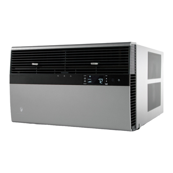
Friedrich KUHL R-410A Service Manual
115 & 208-230-volt cool only, 208-230-volt cool with electric heat, 208-230-volt heat pump with electric heat, 115-volt heat pump
Hide thumbs
Also See for KUHL R-410A:
- Service manual (47 pages) ,
- Parts manual (16 pages) ,
- Service and parts manual (17 pages)
Table of Contents
Advertisement
Room Air Conditioners
Standard Chassis R-410A Models
208-230-Volt:
208-230-Volt: ES12M33, ES15M33, EM18M34, EM24M35, EL36M35
208-230-Volt: YS12M33, YM18M34, YL24M35
Kuhl-ServMan (5-10)
AUTO
°F °C
AUTO
CONTINUOUS
AUTO
SYSTEM
FAN MODE
SCHEDULE
FAN SPEED
Cool Only
115-Volt:
SS08M10, SS10M10, SS12M10, SS14M10
SS12M30, SS15M30, SM18M30, SM21M30
SM24M30, SL28M30, SL36M30
Cool with Electric Heat
Heat Pump with Electric Heat
Heat Pump
115-Volt: YS10M10
Advertisement
Table of Contents

Related Manuals for Friedrich KUHL R-410A


Summary of Contents for Friedrich KUHL R-410A
- Page 1 Room Air Conditioners Standard Chassis R-410A Models 115-Volt: 208-230-Volt: 208-230-Volt: ES12M33, ES15M33, EM18M34, EM24M35, EL36M35 208-230-Volt: YS12M33, YM18M34, YL24M35 115-Volt: YS10M10 Kuhl-ServMan (5-10) AUTO °F °C AUTO CONTINUOUS AUTO SYSTEM FAN MODE SCHEDULE FAN SPEED Cool Only SS08M10, SS10M10, SS12M10, SS14M10 SS12M30, SS15M30, SM18M30, SM21M30 SM24M30, SL28M30, SL36M30 Cool with Electric Heat...
-
Page 2: Table Of Contents
Table Of Contents Important Safety Information ... 2-4 Introduction ... 5 Model and Serial Number Location ... 5 Unit Identifi cation ... 6 Performance Data and Specifi cations ... 7 Installation Information/Sleeve Dimensions/Circuit Rating ... 8 Electrical Data ... 9 Before Operating the Unit ...10 Control Panel Operation ...11 Alerts ...12-14... -
Page 3: Important Safety Information
IMPORTANT SAFETY INFORMATION The information contained in this manual is intended for use by a qualifi ed service technician who is familiar with the safety procedures required for installation and repair, and who is equipped with the proper tools and test instruments required to service this product. Installation or repairs made by unqualifi... - Page 4 • ever operate the A/C unit with wet hands. • se air conditioner on a single dedicated circuit within the specifi ed amperage rating. • se on a properly grounded outlet only. •...
- Page 5 fi re and minor to serious property damage. WATER DAMAGE HAZARDS: • mproper installation, maintenance or servicing of the air conditioner unit can result in water damage to personal items or property. •...
-
Page 6: Introduction
This service manual is designed to be used in conjunction with the installation and operation manuals provided with each air conditioning system. This service manual was written to assist the professional RAC (Room Air Conditioner) service technician to quickly and accurately diagnose and repair malfunctions. -
Page 7: Unit Identifi Cation
UNIT IDENTIFICATION 1st Digit – Function S = Straight Cool, Value Series Y = Heat Pump E = Electric Heat 2nd Digit S = Small Chassis M = Medium Chassis L = Large Chassis 3rd and 4th Digit - Approximate BTU/HR in 1000s (Cooling) Heating BTU/Hr capacity listed in the Specifi... -
Page 8: Performance Data And Specifi Cations
* Operates on 115 volt and is not equipped with supplemental heat. Will not provide heat at temperatures below 40°F. Friedrich room air conditioners are designed to operate in outdoor temperatures from 60° F to 115° F. Due to continuing research in new energy-saving technology, specifi cations are subject to change without notice. -
Page 9: Installation Information/Sleeve Dimensions/Circuit Rating
Unit placement If your air conditioner can be placed in a window or wall that is shaded by a tree i d l i t i n o l l blinds on the sunny side of the dwelling will also add to your unit’s efficiency. -
Page 10: Electrical Data
Do NOT alter the service cord or plug. Do NOT use an extension cord. Refer to the table above for proper receptacle and fuse type. The consumer - through the AHAM Room Air Conditioner Certifi cation Program - can be certain that the AHAM Certifi cation Seal accurately states the unit’s cooling and heating capacity rating, the amperes and the energy effi... -
Page 11: Before Operating The Unit
Test the power cord All Friedrich room air conditioners are shipped from the factory with a Leakage Current Detection Interrupter (LCDI) equipped power cord. The LCDI device on the end of the cord meets the UL and NEC requirements for cord connected air conditioners. -
Page 12: Control Panel Operation
Control Panel Operation Let’s check out how to control your air conditioner. On the control panel, just to the left of the POWER , is a liquid crystal display (LCD). All of the control panel function buttons and mode icons can be viewed in Figure 1. -
Page 13: Alerts
Protection Alert (Freeze) – If the room freeze protection is active, the display indicates this by showing Room Freeze Protection "FRZ". Once temperature is less than 40° F (4° C), and the air conditioner is equipped with electric heat, the room freeze protection will activate. The air conditioner will run high fan and electric heat until the room temperature reaches 46°... - Page 14 SYSTEM MODE SPEED SCHEDULE User presses to toggle the format between 12HR and 24HR display. To exit the selection process and accept the change, press the key. Clock Type – You may select between a 12 hr and 24 hr clock. When 1224 is displayed press the key then press to toggle between 12 hr and 24 hr clock.
- Page 15 This can be caused by many things including the size of the unit, the heat load on the room or other factors. Friedrich allows you to select the appropriate temperature offset to make the temperature readout as accurate as possible for your application.
-
Page 16: Remote Control Operation
Remote Control Operation Remote Control – Refer to Figures 11 and 12 during operation description. Getting Started – Install two (2) AAA batteries in the battery compartment located on the back of the unit. Operation – The remote control should be within 25 feet of the air conditioner for operation (Refer to Figure 10 for effectiveness). -
Page 17: Remote Control Operation
Remote Control Operation (Continued) Figure 1 SYSTEM TEMPERATURE SCHEDULE Figure 2 AUTO ICON SYSTEM MODE MODE SPEED SCHEDULE COOL HEAT FAN ONLY ICON ICON ICON DISPLAY FAN MODE POWER TEMPERATURE DOWN FAN SPEED ICON 2 X 16 SEGMENT DISPLAY FRR005 °F / °C ICONs FRR006... -
Page 18: Electronic Control System Maintenance
ELECTRONIC CONTROL SYSTEM MAINTENANCE Introduction This section contains information on the maintenance alerts, temperature limiting, diagnostic test and how to access. The electronic control system has a built in maintenance sub system which works constantly behind the scenes to help identify problems with the air conditioner or control system. -
Page 19: Electronic Control System Maintenance Operation
Electronic Control System Maintenance Operation To Enter the Maintenance Section: Press SYSTEM+SCHEDULE+BACK+DISPLAY/ENTER for 6 seconds. There are 5 maintenance sub-menus M1 through M5. Maintenance Sub-Menus M1 – Temperature High Limit M2 – Temperature Low Limit M3 – Test Mode Access M4 –... - Page 20 Temperature High Limit Maintenance function 1 is ready to be selected. Press DISPLAY/ENTER to access the function. User presses to increment or decrement the upper temperature limit. 99°F is the maximum upper limit. The current stored high limit is displayed when the screen is selected.
- Page 21 M4 – Switch Access (Unit Configuration) FACTORY USE ONLY M5 – Error Codes & History Maintenance funtion 5 is ready to be selected. Press DISPLAY/ENTER to access the function. The error code display shows the error code number on the left, and the error code history on the right.
-
Page 22: Unit Operation
UNIT OPERATION There are two basic ways to operate the unit - Front Panel and Wallstat. The Front Panel and Wallstat are never active at the same time. Switching between these modes is controlled via the (FP) jumper on the Wallstat connector. When the jumper is ON, the mode = Front Panel. -
Page 23: Cool-Heat Set Points
COOL-HEAT SET POINTS The air conditioner control system is designed to control different product configurations with a select set of features. Some models just cool, some cool and heat with electric heat, and others cool and heat with a heat pump and/or electric heat. -
Page 24: Electronic Control Sequence Of Operation
ELECTRONIC CONTROL SEQUENCE OF OPERATION Compressor and Reversing Valve Control Active Mode Cooling Heat - Heat Pump Heat - Electric Fan Only * The Reversing valve stays in the last state until a call for heat or cooling (see fi gure below) Cooling Mode Once the ambient temperature rises past the cool demand threshold (Cool Set Point + 1.5 ˚F) (see fi... - Page 25 Heating Mode Control Operation There are two heating methods: Heat Pump and Electric Resistance Heat. There are 3 types of units that provide heating: Heat Pump Only (Model YS10M10) Heat Pump with Electric Heat and Cool with Electric Heat. Heat Control Operation Heat Pump Only Once the ambient temperature falls below the Heating Demand Threshold (1.5 ˚F Below the Heat Set Point Temperature), the heating cycle begins.
- Page 26 Heat Pump With Electric Heat Operation This heating is more complex due to the possibility of two heating methods. If the ambient indoor temperature is be- low the heat demand threshold (1.5˚F below the heat set point temperature), and the compressor is not locked out, turn on compressor.
- Page 27 Heat Pump With Electric Heat Operation (Continued) Condition 2 If the Δ (delta) (set point temperature minus the ambient indoor temperature) is greater than 5 ˚F, then the unit will switch to electric heat, if available. The unit will continue to operate with electric heat until the heat demand is satisfi ed. Note that the electric heat switches on after the Δ...
- Page 28 Compressor Lock Out Time The lockout feature ensures that the compressor is de-energized for a period of time. The timer varies randomly from 180 to 240 seconds The compressor lockout is initiated every time the compressor is “off” due to: (1) Satisfying the temperature set point (2) Changing mode to fan only or heat (3) Turning the unit off...
- Page 29 Fan Operation (Front Panel Mode) Heat – Cool – Auto – Fan Only Models starting with SS, SM have 4 speeds. Models with SL, and all Kuhl+ have 3 speeds Continuous "On" " Turns On or Off with AUTO heat or cool demand Mode...
-
Page 30: Unit Operation With A Wall-Stat
UNIT OPERATION WITH A WALL-STAT Front Panel Display Operation in Wall-Stat Mode The indoor ambient temperature sensor is disabled. All buttons are disabled with the following exception: A. Maintenance commands. B. The user menu for Freeze protection (Display/Enter button for Kuhl+ only units). C. -
Page 31: Removing The Front Cover And Unit Chassis
REMOVING THE FRONT COVER WARNING ELECTRIC SHOCK HAZARD Disconnect power to the unit before servicing. Failure to follow this warning could result in serious injury or death. Remove the decorative front cover by using the tool provided (see fi gure below). Tighten the four (4) captive screws as indicated by the arrows in the fi... -
Page 32: Replacing The Id Coil Thermistor
REPLACING THE INDOOR COIL THERMISTOR WARNING ELECTRIC SHOCK HAZARD Disconnect power to the unit before servicing. Failure to follow this warning could result in serious injury or death. Remove the decorative front cover (see page 30). Remove all indicated screws below (8 total, see fi gure below). -
Page 33: Low Voltage Interface Connector
Thermostat Selection Friedrich recommends the use of either the Friedrich RT4 or RT5. These thermostats are single stage heat/cool, manual changeover. The RT4 is a digital display thermostat with single speed fan control. The RT5 features a digital display, two fan speed selection, fi... -
Page 34: Remote Wall Thermostat
Fresh air and exhaust control Your air conditioner has the ability to bring fresh air into the room or exhaust stale air out of the room. The control slide is found on the upper part of the unit (See Figure). -
Page 35: Components Testing
COMPONENTS TESTING FAN MOTOR A single phase permanent split capacitor motor is used to drive the evaporator blower and condenser fan. A self-resetting overload is located inside the motor to protect against high temperature and high amperage conditions. (See Figure 23) WARNING ELECTRIC SHOCK HAZARD Disconnect power to the unit before... -
Page 36: Components Testing
COMPONENTS TESTING HEATING ELEMENT All heat pumps and electric heat models are equipped with a heating element with the exception of model YS10M10. The other “YS” and “ES” models are equipped with a 3.3 KW element. The “YM” and “EM” models are equipped with a 4.0 KW element. -
Page 37: Refrigeration Sequence Of Operation
REFRIGERATION SEQUENCE OF OPERATION A good understanding of the basic operation of the refrigeration system is essential for the service technician. Without this understanding, accurate troubleshooting of refrigeration system problems will be more diffi cult and time consuming, if not (in some cases) entirely impossible. The refrigeration system uses four basic principles (laws) in its operation they are as follows: 1. - Page 38 Introduce liquid refrigerant charge into the high side of the system. • For low side pressure charging of R-410A, use a charging adaptor. • Use Friedrich approved R-410A fi lter dryers only. WARNING Refrigeration system under high pressure Do not puncture, heat, expose to fl ame or incinerate.
-
Page 39: Sealed Refrigeration System Repairs
R-410A SEALED REFRIGERATION SYSTEM REPAIRS SEALED SYSTEM REPAIRS TO COOL-ONLY MODELS REQUIRE THE INSTALLATION OF A LIQUID LINE DRIER. EQUIPMENT REQUIRED: 1. Voltmeter 2. Ammeter 3. Ohmmeter 4. E.P.A. Approved Refrigerant Recovery System 5. Vacuum Pump (capable of 200 microns or less vacuum.) 6. - Page 40 Method Of Charging / Repairs The acceptable method for charging the WallMaster system is the Weighed in Charge Method. The weighed in charge method is applicable to all units. It is the preferred method to use, as it is the most accurate. The weighed in method should always be used whenever a charge is removed from a unit such as for a leak repair, compressor replacement, or when there is no refrigerant...
-
Page 41: Undercharged Refrigerant Systems
WARNING ELECTRIC SHOCK HAZARD Turn off electric power before service or installation. Extreme care must be used, if it becomes necessary to work on equipment with power applied. Failure to do so could result in serious injury or death. Undercharged Refrigerant Systems An undercharged system will result in poor performance (low pressures, etc.) in both the heating and cooling cycle. -
Page 42: Restricted Refrigerant System
Restricted Refrigerant System Troubleshooting a restricted refrigerant system can be diffi cult. The following procedures are the more common problems and solutions to these problems. There are two types of refrigerant restrictions: Partial restrictions and complete restrictions. A partial restriction allows some of the refrigerant to circulate through the system. -
Page 43: Hermetics Components Check
HERMETIC COMPONENTS CHECK WARNING BURN HAZARD Proper safety procedures must be followed, and proper protective clothing must be worn when working with a torch. Failure to follow these procedures could result in moderate or serious injury. METERING DEVICE Capillary Tube Systems All units are equipped with capillary tube metering devices. -
Page 44: Reversing Valve Description/Operation
REVERSING VALVE DESCRIPTION/OPERATION The Reversing Valve controls the direction of refrigerant fl ow to the indoor and outdoor coils. It consists of a pressure-operated, main valve and a pilot valve actuated by a solenoid plunger. The solenoid is energized during the heating cycle only. -
Page 45: Testing The Coil
TESTING THE REVERSING VALVE SOLENOID COIL WARNING ELECTRIC SHOCK HAZARD Unplug and/or disconnect all electrical power to the unit before performing inspections, maintenances or service. Failure to do so could result in electric shock, serious injury or death. The solenoid coil is an electromagnetic type coil mounted on the reversing valve and is energized during the operation of the compressor in the heating cycle. -
Page 46: Procedure For Changing Reversing Valve
Touch Test in Heating/Cooling Cycle WARNING BURN HAZARD Certain unit components operate at temperatures hot enough to cause burns. Proper safety procedures must be followed, and proper protective clothing must be worn. Failure to follow these procedures could result in minor to moderate injury. The only definite indications that the slide is in the mid- position is if all three tubes on the suction side of the valve are hot after a few minutes of running time. -
Page 47: Compressor Checks
COMPRESSOR CHECKS WARNING ELECTRIC SHOCK HAZARD Turn off electric power before service or installation. Extreme care must be used, if it becomes necessary to work on equipment with power applied. Failure to do so could result in serious injury or death. - Page 48 Single Phase Resistance Test WARNING ELECTRIC SHOCK HAZARD Turn off electric power before service or installation. Extreme care must be used, if it becomes necessary to work on equipment with power applied. Failure to do so could result in serious injury or death.
-
Page 49: Compressor Replacement
COMPRESSOR REPLACEMENT Recommended procedure for compressor replacement WARNING RISK OF ELECTRIC SHOCK Unplug and/or disconnect all electrical power to the unit before performing inspections, maintenances or service. Failure to do so could result in electric shock, serious injury or death. Be certain to perform all necessary electrical and refrigeration tests to be sure the compressor is actually defective before replacing. - Page 50 SPECIAL PROCEDURE IN THE CASE OF MOTOR COMPRESSOR BURNOUT WARNING ELECTRIC SHOCK HAZARD Turn off electric power before service or installation. Failure to do so may result in personal injury, or death. WARNING HIGH PRESSURE HAZARD Sealed Refrigeration System contains refrigerant and oil under high pressure.
-
Page 51: Routine Maintenance / Battery Check / Change
ROUTINE MAINTENANCE WARNING ELECTRIC SHOCK HAZARD Turn off electric power before inspections, maintenances, or service. Extreme care must be used, if it becomes necessary to work on equipment with power applied. Failure to do so could result in serious injury or death. - Page 52 ROUTINE MAINTENANCE (Continued) NOTICE Do not drill holes in the bottom of the drain pan or the underside of the unit. Not following this notice could result in damage to the unit or condensate water leaking inappropriately which could cause water damage to surrounding property.
- Page 53 ROUTINE MAINTENANCE (Continued) Standard Filter Cleaning Installation Instructions STEP 1. Figure 1 Remove the filter by grabbing it from its handle, lifting it up and swinging it out. Figure 2 STEP 2. NOTE: Figure 3 STEP 3. Figure 4 FILTER GRIP HANDLE STEP 4.
- Page 54 Noises All air conditioners make some noise. Friedrich units are designed to operate as quietly as possible. An air conditioner mounted in a wall is quieter than one mounted in a window. It is important to ensure that the chassis seal gasket is properly installed (refer to installation instructions).
-
Page 55: Service And Assistance
Window Installation Kits (Standard in Kühl Models without Heat) KWIKS – For all ES and YS models. KWIKM – For all EM and YM models. KWIKL – For all EL and YL models. See www.friedrich.com for additional accessories for your unit. -
Page 56: Performance Test Data Sheet And Sizing Guide
ROOM AIR CONDITIONER UNIT PERFORMANCE TEST DATA SHEET JOB NAME________________________________ TECHS NAME____________________________________ DATE: _______________ MODEL:_______________ SERIAL:________________ HOW IS ALL OF THE INSTALLATION? IS A C H AS S IS S E A L G AS K E T IN T A L L E D ? -
Page 57: Error Codes And Alarm Status
ERROR CODES AND ALARM STATUS Maintenance Error ICON Code Front Panel Button Stuck For More Flash Than 20 Seconds Input Voltage Out of Specification (103 Flash - 127 / 187 - 253) Indoor Temperature Sensor is Open or Flash Shorted Indoor Coil Temperature Sensor is Flash Open or Shorted... -
Page 58: Troubleshooting
Be sure to use exhaust vent fans while cooking or bathing and, if possible, try not to use heat producing appliances during the hottest part of the day. Allow additional time for the air conditioner to cool off a very hot room. - Page 59 Possible Solution Do not try to operate your air conditioner in the cooling mode when the outside temperature is below 60° F (16° C). The unit will not cool properly, and the unit may be damaged.
- Page 60 COOLING ONLY ROOM AIR CONDITIONERS: TROUBLESHOOTING TIPS Low voltage Temperature not set cold enough or room air thermistor inoperative Compressor hums but cuts off on Compressor overload does not run Open or shorted compressor windings Open overload Open capacitor Inoperative system button Broken, loose or incorrect wiring Inoperative system button Broken, loose or incorrect wiring...
- Page 61 COOLING ONLY ROOM AIR CONDITIONERS: TROUBLESHOOTING TIPS Fuse blown or circuit tripped Power cord not plugged in System button in “OFF” position Unit does not run Inoperative system button or open electronic control board Loose or disconnected wiring control board or other components Dirty fi...
- Page 62 Control’s default of 3 minutes wait delay timer inoperative. Replace board. Check voltage with unit operating. Check for other appliances on circuit. Air conditioner should be in a dedicated circuit for proper voltage & fused separately Refer to appropriate wiring diagram Test capacitor and replace if needed.
- Page 63 COOLING ONLY ROOM AIR CONDITIONERS: TROUBLESHOOTING TIPS Sublimation: When unconditioned saturated, outside air mixes with conditioned air, condensation forms on the cooler surfaces Water “spitting” into room Downward pitch of installation is too steep towards back of unit Restricted coil or dirty fi lter Insuffi...
- Page 64 HEAT / COOL ONLY ROOM AIR CONDITIONERS: TROUBLESHOOTING TIPS Bad indoor ambient thermistor Room temperature Fan speed too low uneven Opened door, windows, etc. (Heating cycle) ATSF (room air sampling feature) disabled Bad outdoor coil thermistor Unit will not defrost (Heat pump only models) Temperature below 32°F/ 0°C...
- Page 65 HEAT PUMP ROOM AIR CONDITIONERS: TROUBLE SHOOTING TIPS Incorrect wiring Defective solenoid coil Unit cools when heat is called for Reversing valve fails to shift Inoperative system switch Heating capillary tube partially restricted Cooling adequate, Check valve leaking internally but heating insuffi...
- Page 66 HEAT PUMP ROOM AIR CONDITIONERS: TROUBLE SHOOTING TIPS REFRIGERANT SYSTEM DIAGNOSIS - HEATING CYCLE HIGH SUCTION PRESSURE LOW SUCTION PRESSURE Low Airfl ow Outdoor Ambient Too High Across Outdoor Coil for Operation in Heating Refrigerant System Restriction Undercharged Moisture in System ELECTRICAL TROUBLESHOOTING CHART - HEAT PUMP Is Line Voltage Present at the Solenoid...
- Page 67 TROUBLESHOOTING TOUCH TEST CHART: TO SERVICE REVERSING VALVES VALVE OPERATING CONDITION Normal Cooling Cool Normal Heating Cool Check Electrical circuit and coil Check refrigeration charge Valve will not shift from cool Cool to heat. Cool Valve will not shift from cool Cool to heat.
-
Page 68: Electronic Control Board Components Identifi Cation
ELECTRONIC CONTROL BOARD COMPONENTS IDENTIFICATION Front DISCHARGE Reversing Valve Battery Compartment Max Speed High Speed Med Speed Low Speed User Interface connector T-stat Terminals Transformer voltage Selector Switch 115/230 Volts Sample board for Kuhl+ unit Back Transformer 115/230 Volts... - Page 69 REMOTE WALL THERMOSTAT WIRING DIAGRAMS COOL W/O ELECTRIC HEAT Electronic Control Board 24 VAC Connections C GH GL B GH GL O W RC RH C RT5 Thermostat LEGEND FOR T-STAT WIRING HARNESS Common Terminal Call for High Fan Call for Low Fan Reversing Valve Coil for Cooling Call for Heat...
-
Page 70: Wiring Diagrams
ELECTRONIC CONTROL COOL ONLY MODELS SS08M10A, SS10M10A, SS12M10A, SS14M10A SS12M30A, SS15M30A SM18M30A, SM21M30A, SM24M30A COMPRESSOR BLACK CAPACITOR CAPACITOR BRACKET GREEN TO CHASSIS BLUE TO INNERWALL/ MOTOR MOUNT SCHEMATIC HIGH MEDIUM L2 OR N COMPRESSOR COMP ELECTRONIC CONTROL L E G E N D - CAPACITOR - COMPRESSOR COMPR... -
Page 71: Wiring Diagram
COMPRESSOR BLACK CAPACITOR BRACKET GREEN TO CHASSIS BLUE SCHEMATIC COMPR KUHL ELECTRONIC CONTROL COOL ONLY MODELS SL28M30A, SL36M30A RELAY BLACK RELAY BLUE RELAY RELAY SOLID STATE RELAY WHITE BLUE COMP RELAY BLACK WHITE CAPACITOR BROWN MOTOR TO INNERWALL/ MOTOR MOUNT HIGH MEDIUM L2 OR N... - Page 72 KUHL+ ELECTRONIC CONTROL COOL WITH ELECTRIC HEAT MODELS ES12M33A, ES15M33A EM18M34A, EM24M34A COMPRESSOR HEATER ORANGE BLACK CAPACITOR CAPACITOR GREEN BRACKET TO CHASSIS BLUE TO INNERWALL/ MOTOR MOUNT SCHEMATIC HIGH MEDIUM ELECTRIC HEAT ELECTRIC HEAT L2 OR N COMPRESSOR COMP ELECTRONIC CONTROL L E G E N D - CAPACITOR COMPR - COMPRESSOR...
- Page 73 COOL WITH ELECTRIC HEAT MODEL C OMP R E S S OR OL P B LAC K R E D C AP AC IT O R B R AC K E T G R E E N T O C H AS S IS B LUE S C HE MAT IC KUHL+...
- Page 74 KUHL+ ELECTRONIC CONTROL HEAT PUMP ONLY MODEL YS10M10A COMPRESSOR COIL, SOLENOID BLACK CAPACITOR CAPACITOR BRACKET GREEN TO CHASSIS BLUE TO INNERWALL/ MOTOR MOUNT SCHEMATIC HIGH MEDIUM REVERSE CYCLE L2 OR N COMPRESSOR COMP ELECTRONIC CONTROL L E G E N D - CAPACITOR - COMPRESSOR COMPR...
- Page 75 HEAT PUMP WITH ELECTRIC HEAT MODELS COMPRESSOR BLACK CAPACITOR BRACKET GREEN TO CHASSIS BLUE SCHEMATIC COMPR KUHL+ ELECTRONIC CONTROL YS12M33A, YM18M34A UI HOLDER ELECTRONICS ASY COIL, SOLENOID BLACK RELAY FAN 4 RELAY BLACK FAN 3 RELAY HEATER BLUE FAN 2 RELAY ORANGE ORANGE...
- Page 76 ELECTRONIC CONTROL HEAT PUMP WITH ELECTRIC HEAT MODEL YL24M35A COMPRESSOR SOLID STATE RELAY HEATER ORANGE SOLID STATE RELAY BLACK WHITE BLACK YELLOW CAPACITOR CAPACITOR BRACKET GREEN TO CHASSIS BLUE TO INNERWALL/ MOTOR MOUNT SCHEMATIC HIGH MEDIUM ELECTRIC HEAT ELECTRIC HEAT REVERSING CYCLE COMPRESSOR COMP...
-
Page 77: Thermistors' Resistance Values
THERMISTORS’ RESISTANCE VALUES (This Table Applies to All Thermistors) INDOOR AIR SENSOR TEMP RESISTENCE (K Ohms) CENTR 210.889 225.548 240.224 178.952 190.889 202.825 151.591 161.325 171.059 128.434 136.363 144.292 108.886 115.340 121.794 92.411 97.662 102.912 78.541 82.812 87.083 66.866 70.339 73.812 57.039 59.864... -
Page 78: Remote Control Replacement Instructions
Remote Control not being able to operate the Air Conditioning Unit properly. Step 1. A. Locate the Model # of your Air Conditioner. B. Identify the prefix (First 2 Letters) of your unit’s model #. - Page 79 To save the setting in the Remote Control, press and hold the Remote Control FAN SPEED configuration number on the Remote Control flashes. The Remote Control is now configured to work with the air conditioner. FAN SPEED Keys simultaneously for approximately 6 seconds until Remote Control’s OPT# Code...
-
Page 80: User Interface Service Kit
Replacement Instructions For Use with Kühl (cool only models) ATTENTION! - Please read these instructions completely before attempting replacement. Always unplug the power supply from the power supply receptacle. Contents: • User Interface (UI) • Ribbon Cable • 2 – Mounting screws for UI •... -
Page 81: Instructions For Using Cooling Load Estimate Form
The result is the total estimated design cooling load in BTU per hour. For best results, a room air conditioner unit or units having a cooling capacity rating (determined in accordance with the NEMA Standards Publication for Room Air Conditioners, CN 1-1960) as close as possible to the estimated load should be selected. -
Page 82: Cooling Load Estimate Form
LIGHTS AND ELECTRICAL EQUIPMENT IN USE DOORS AND ARCHES CONTINUOUSLY OPENED TO UNCONDITIONED SPACE: (TOTAL LINEAR FEET OF WIDTH.) SUBTOTAL 10. TOTAL COOLING LOAD (BTU per hour to be used for selection of room air conditioner(s).) FACTORS QUANTITY nside Shades* Shades* ___ _sq. -
Page 83: Heat Load Form
The heat load form on the following page may be used by servicing personnel to determine the heat loss of a conditioned space and the ambient winter design temperatures in which the unit will heat the calculated space. The upper half of the form is for computing the heat loss of the space to be conditioned. - Page 84 HEATING LOAD FORM FRIEDRICH ROOM UNIT HEAT PUMPS WALLS: (Linear Feet) 2” Insulation Average WINDOWS & DOORS (Area, sq. ft.) Single Glass: Double Glass: INFILTRATION - WINDOWS & DOORS: AVG. CEILING: (Area, Sq. Ft.) Insulated (6”) Insulated (2”) Built-up Roof (2” insulated Built-up Roof (1/2”...
-
Page 85: Warranty
ANY PART: If any part supplied by FRIEDRICH fails because of a defect in workmanship or material within twelve months from date of original purchase, FRIEDRICH will repair the product at no charge, provided room air conditioner is reasonably accessible for service. Any additional labor cost for removing inaccessible units and/or charges for mileage related to travel by a Service Agency that exceeds 25 miles one way will be the responsibility of the owner. - Page 86 TECHNICAL SUPPORT CONTACT INFORMATION FRIEDRICH AIR CONDITIONING CO. Post Offi ce Box 1540 · San Antonio, Texas 78295-1540 4200 N. Pan Am Expressway · San Antonio, Texas 78218-5212 (210) 357-4400 · 877-599-5665 x 846 · FAX (210) 357-4490 Email: tac@friedrich.com www.friedrich.com...
- Page 87 FRIEDRICH AIR CONDITIONING CO. Post Offi ce Box 1540 · San Antonio, Texas 78295-1540 4200 N. Pan Am Expressway · San Antonio, Texas 78218-5212 (210) 357-4400 · FAX (210) 357-4490 www.friedrich.com Kuhl-ServMan (5-10) Printed in the U.S.A.