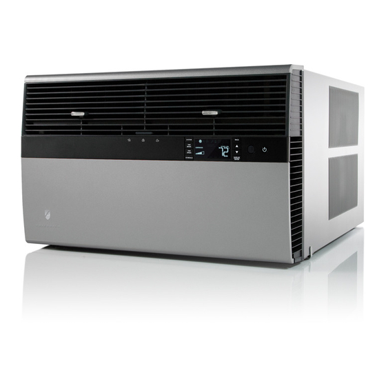
Friedrich Kuhl SM18M30 User Manual
115-volt & 208-230-volt standard chassis models
Hide thumbs
Also See for Kuhl SM18M30:
- Installation and operating manual (132 pages) ,
- Service manual (87 pages) ,
- Installation and operation manual (44 pages)
Table of Contents
Advertisement
Room Air Conditioners
Standard Chassis Models
115-Volt:
208-230-Volt:
115-Volt:
208-230-Volt:
920-198-00 (11-09)
AUTO
°F °C
AUTO
CONTINUOUS
AUTO
SYSTEM
FAN MODE
SCHEDULE
FAN SPEED
SS08M10, SS10M10, SS12M10, SS14M10
SS12M30, SS15M30, SM18M30, SM21M30
SL25M30, SL28M30, SL36M30
YS10M10
ES12M33, ES15M33, YS12M33, EM18M34,
YM18M34, EL25M35, EL36M35, YL24M35
Advertisement
Table of Contents

Related Manuals for Friedrich Kuhl SM18M30


Summary of Contents for Friedrich Kuhl SM18M30
- Page 1 Room Air Conditioners Standard Chassis Models 115-Volt: SS08M10, SS10M10, SS12M10, SS14M10 208-230-Volt: SS12M30, SS15M30, SM18M30, SM21M30 SL25M30, SL28M30, SL36M30 115-Volt: YS10M10 208-230-Volt: ES12M33, ES15M33, YS12M33, EM18M34, YM18M34, EL25M35, EL36M35, YL24M35 920-198-00 (11-09) AUTO °F °C AUTO CONTINUOUS AUTO SYSTEM FAN MODE SCHEDULE FAN SPEED...
- Page 2 Congratulations! Thank you for your decision to purchase the Friedrich High Effi ciency Air Conditioner. Your new Friedrich has been carefully engineered and manufactured to give you many years of dependable, effi cient operation, maintaining a comfortable temperature and humidity level. Many extra features have been built into your unit to assure quiet operation, the greatest circulation of cool, dry air, and the most economic operation.
-
Page 3: Table Of Contents
920-198-00 Table of Contents Safety Precautions ... 4 Unpacking Instructions... 5 WARNING: Before Operating Your Unit ... 6 Standard Filter Cleaning / Installation Instructions ... 7 Premium Carbon Filter Installation Instructions ... 8 Control Panel Operation ... 10 Add a Remote Thermostat ... 14 Remote Thermostat Selection ... -
Page 4: Safety Precautions
Safety Precautions Your safety and the safety of others are very important. We have provided many important safety messages in this manual and on your appliance. Always read and obey all safety messages. This is a safety Alert symbol. This symbol alerts you to potential hazards that can kill or hurt you and others. All safety messages will follow the safety alert symbol with the word “WARNING”... -
Page 5: Unpacking Instructions
Unpacking Instructions STEP 1. Cut all 4 packing straps. STEP 2. Remove wooden shipping bar dividers. STEP 3. Remove top foam pads. STEP 4. Slowly remove outer box, careful not to loosen decorative front. 920-198-00 STEP 5. Slide the foam front support forward STEP 6. -
Page 6: Warning: Before Operating Your Unit
Test the power cord All Friedrich room air conditioners are shipped from the factory with a Leakage Current Detection Interrupter (LCDI) equipped power cord. The LCDI device on the end of the cord meets the UL and NEC requirements for cord connected air conditioners. -
Page 7: Standard Filter Cleaning / Installation Instructions
Standard Filter Cleaning / Installation Instructions STEP 1. Swing the door open and remove the fi lter by grasping the fi lter grip and pushing the fi lter holder upward and outward. Figure 2 Figure 3 FILTER GRIP 920-198-00 STEP 2. Slide the fi... -
Page 8: Premium Carbon Filter Installation Instructions
Premium Carbon Filter Installation Instructions STEP 1. Remove the fi lter from the unit as per the instructions on the inside of the fi lter door. STEP 2. Hold the fi lter at the top and slide the fi lter grip out as shown in Figure 4. - Page 9 920-198-00 THIS PAGE INTENTIONALLY LEFT BLANK...
-
Page 10: Control Panel Operation
Control Panel Operation Let’s check out how to control your air conditioner. On the control panel, just to the left of the POWER , is a liquid crystal display (LCD). All of the control panel function buttons and mode icons can be viewed in Figure 8. -
Page 11: Special Functions
Room Freeze Protection "FRZ". Once the condition is satisfi ed, the “FRZ” display is removed. If the room temperature is less than 40° F (4° C), and the air conditioner is equipped with electric heat, the room freeze protection will activate. The air conditioner will run high fan and electric heat until the room temperature reaches 46°... - Page 12 SYSTEM EXIT MODE SPEED SCHEDULE User presses to toggle the format between 12HR and 24HR display. To exit the selection process and accept the change, press the key. BACK Clock Type – You may select between a 12 hr and 24 hr clock. When 1224 is displayed press the key then press DISPLAY...
- Page 13 This can be caused by many things including the size of the unit, the heat load on the room or other factors. Friedrich allows you to select the appropriate temperature offset to make the temperature readout as accurate as possible for your application.
-
Page 14: Add A Remote Thermostat
Control Panel LCD. Remote Thermostat Selection Friedrich recommends the use of either the RT4 or RT5. The RT4 is a digital display thermostat with single speed fan control. The RT5 features a digital display, two fan speed selection, battery backup and backlight. -
Page 15: Remote Control Operation
Remote Control Operation Remote Control – Refer to Figures 11 and 12 during operation description. Getting Started – Install two (2) AAA batteries in the battery compartment located on the back of the unit. Operation – The remote control should be within 25 feet of the air conditioner for operation (Refer to Figure 10 for effectiveness). - Page 16 Figure 11 SYSTEM TEMPERATURE SCHEDULE Figure 12 AUTO ICON SYSTEM MODE MODE SPEED SCHEDULE ICON 920-198-00 COOL HEAT FAN ONLY ICON ICON ICON 2 X 16 SEGMENT DISPLAY DISPLAY FAN MODE POWER TEMPERATURE DOWN FAN SPEED FRR005 °F / °C ICONs FRR006...
-
Page 17: Airfl Ow Selection And Adjustment
920-198-00 Airflow Selection and Adjustment Figure 13 Air flow direction adjustment The airfl ow path may be adjusted to distribute air independently from the left or right side of the discharge opening. Each of the banks of louvers can be directed left, right, up or down in order to achieve the most optimum airfl... -
Page 18: Installation Instructions
IMPORTANT: Before you begin the actual installation of your air conditioner, check local electrical codes and the information below. Your air conditioner must be connected to a power source with the same alternating current (A.C.) voltage and amperage as marked on the name plate located on the chassis. - Page 19 INSTALLATION HARDWARE AND ACCESSORY DETAIL ITEM 1 ITEM 4 ITEM 7 ITEM 11 ITEM 10 ITEMS NOT TO SCALE ITEM DE SCRIP TION SHELL MOUNT ING PARTS SUPPORT BRACKET SCREW, 10-24 x 1" HEX HEAD 10-24 FLAT WELD NUT SCREW, SHEET METAL #12 x 2" WINGBOARD ANGLE MOUNTING WINGBOARD ANGLE, TOP WINGBOARD ANGLE, SIDE...
-
Page 20: Standard Window Installation
Standard Window Installation NOTE: Hardware and accessories used during installation are shown on page 18. Each part will be referred as Item No. STEP 1. Remove the chassis Entrygard retainer by removing the far right screw (See Figure 14), save this screw to reattach the chassis retainer after installation (Step 12). - Page 21 CAUTION Remove Shipping Blocks Prior to operating the unit remove the foam shipping blocks. Failure to do so may result in damage to the unit which is not covered by the manufacturer’s warranty! STEP 5. Check the window sill and frame to be sure they are in good condition and fi...
- Page 22 Figure 17 TOP ANGLE (ITEM 5) CABINET Figure 18 CENTER CABINET IN WINDOW SIDE TO SIDE DRILL (3) 5/32” DIA. PILOT HOLES AND INSTALL (3) #12 x 2” LONG SCREWS (ITEM 4) WINDOW SILL 920-198-00 SIDE ANGLE (ITEM 6) 2 REQUIRED SILL PLATE LOCATE SILL PLATE GUIDE CHANNEL JUST BACK OF WINDOW SILL...
- Page 23 Figure 19 SPACER SHOULD BE USED BETWEEN WALL AND BRACKET WHEN INSTALLED ON ALUMINUM OR VINYL SIDING. Figure 20 920-198-00 3/8” SLOPE DOWN SUPPORT BRACKET (ITEM 1) #12 x 2” SCREW (ITEM 4) 10-24 x FLAT WELD NUT (ITEM 3) CONDENSER AIR OUTLET CONDENSER...
- Page 24 Figure 21 STONE LEDGE Figure 22 920-198-00 3/8” SLOPE DOWN CONDENSER AIR INLETS #10-24 SCREW #10-24 FLAT WELD NUT #12 x 2” SHEET METAL SCREW (ITEM 4) SPACER 3/8” SLOPE DOWN #10-24 SCREW STRAIGHTEN TAB TO LAY FLAT ALONG THE BOTTOM RAIL OF THE SHELL #10-24 FLAT WELD NUT SECURE THE LONGEST SIDE OF...
- Page 25 Figure 23 Figure 24 920-198-00 3/8” SLOPE DOWN #10-24 SCREW DIMENSION “A” HERE #10-24 FLAT WELD NUT STONE LEDGE OUTSIDE WALL DISCARD SHADED AREA MEASURE DISTANCE “B” TO INSIDE OF THE CHANNEL ON EACH SIDE. CUT HERE AND DISCARD CENTER WASTE MATERIAL.
- Page 26 (Figure 29). CAUTION Excessive Weight Hazard Use two or more people when installing your air conditioner. Failure to do so can result in back or other injury. Figure 25 “J” TYPE SPEED NUT...
- Page 27 Figure 26 TOP OF CABINET PLACE WINGBOARD PANEL IN WINDOW JAM TO COMPRESS THE SPRINGS INSIDE THE RUNNERS, AND SWING THE WINGBOARD PANELS INTO PLACE AS INDICATED BY THE DASHED LINES. WINDOW JAM CLIP (ITEM 10) SECTION A-A SECURE THE SIDE WINGBOARD PANELS TO THE SIDE ANGLES WITH FOUR (4) #8 x 1/2”...
- Page 28 OPTIONAL: The factory assembles the supply cord so that it exits the left side of the unit at the bottom. At the consumer’s discretion, the supply cord can be routed to exit the right side of the unit. To do this, route the supply cord to the right side. Pull the supply cord taunt through the loops (Refer to Cord Routing Change, Figure 37) and route the cord down.
- Page 29 920-198-00 THIS PAGE INTENTIONALLY LEFT BLANK...
-
Page 30: Cord Routing Change
Unplug unit. WARNING Electrical Shock Hazard Make sure your electrical receptacle has the same configuration as your air conditioner’s plug. If different, consult a Licensed Electrician. Do not use plug adapters. Do not use an extension cord. Do not remove ground prong. - Page 31 STEP 18. Carefully push electrical control panel back into chassis. Figure 35 ELECTRICAL CONTROL PANEL STEP 19. Reinstall the 3 screws removed earlier to secure electrical control panel. Figure 36 ELECTRICAL CONTROL PANEL SCREWS (3) (RETAINED FROM STEP 1) 920-198-00 STEP 20.
-
Page 32: Through-The-Wall Installation
Through-the-Wall Installation The following instructions apply to wood, masonry, brick, concrete or cinder block wall construction. STEP 1. Follow steps 1, 2, 3, and 4 of the "STANDARD WINDOW INSTALLATION" instructions beginning on page 20. STEP 2. CABINET PREPARATION – Remove the sill plate from the cabinet by removing two (4) nuts and screws (Figure 38). - Page 33 Figure 38 BEFORE CABINET SILL PLATE TURN SILL PLATE END TO END Figure 39 MAXIMUM WALL THICKNESS CONDENSER AIR INTAKE LOUVERS MODEL SMALL CHASSIS 7-3/8” MEDIUM CHASSIS 7-3/8” LARGE CHASSIS 15-1/8” 920-198-00 CABINET SCREW (4 REQUIRED) NOTE: HOLES IN SILL PLATE MOVED TO BACK SIDE DETAIL A...
- Page 34 Figure 40 CAULK ALL SIDES INSIDE AND OUTSIDE CABINET SHIM TO FILL IN VOID AT THE TOP AND SIDES WITH WOOD AS REQUIRED. ELECTRICAL RECEPTACLE (SEE FIG. 42 FOR LOCATION NOTE) Figure 42 CAULK ALL SIDES INSIDE AND OUTSIDE CABINET MORTAR POINT “X”...
- Page 35 STEP 6. Slide the cabinet into the hole far enough to allow the guide-channel of the sill plate to contact the inside wall surface (Figure 20). STEP 7. Drill three (3) 5/32” diameter pilot holes (use the sill-plate holes as a guide) into the frame and install three (3) #12 x 2" long screws (Item 4) (Figure 20).
-
Page 36: Programmable Thermostat
Programmable Thermostat Your unit features an advanced 7 day programmable thermostat feature that can be used to turn the unit on or off or even change modes and maintain temperatures throughout the day. Factory settings are shown in addendum 1 (Schedule Table with Energy Saving Values). - Page 37 M T W T F S S WAKE SCHEDULE If the user wants the air conditioner to power down for a period of time, pressing a fi fth time will set the unit options to OFF and put the unit into SYSTEM hibernation until the next scheduled period.
-
Page 38: Final Inspection & Start-Up Checklist
Noises All air conditioners make some noise. Friedrich units are designed to operate as quietly as possible. An air conditioner mounted in a wall is quieter than one mounted in a window. It is important to ensure that the chassis seal gasket (Item 14) is properly installed (refer to installation instructions). -
Page 39: Routine Maintenance
Window Installation Kits (Standard in Kühl Models without Heat) KWIKS – For all ES and YS models. KWIKM – For all EM and YM models. KWIKL – For all EL and YL models. See www.friedrich.com for additional accessories for your unit. -
Page 40: Troubleshooting Tips
Be sure to use exhaust vent fans while cooking or bathing and, if possible, try not to use heat producing appliances during the hottest part of the day. ● Allow additional time for the air conditioner to cool off a very hot room. SOLUTION Figure 44... - Page 41 920-198-00 CAUSE ● Do not try to operate your air conditioner in the cooling mode when the outside temperature is below 60° F (16° C). The unit will not cool properly, and the unit may be damaged.
-
Page 42: Addendum 1
Schedule Table with Energy Saving Values Sche dule Day of We e k Pe riod Monday Wake Monday Return Away Return Monday A w ay Monday Night Sche dule Day of We e k Pe riod Tuesday Wake Tuesday Return Away Return Tuesday... - Page 43 LIMITED WARRANTY ANY PART: If any part supplied by FRIEDRICH fails because of a defect in workmanship or material within twelve months from date of original purchase, FRIEDRICH will repair the product at no charge, provided room air conditioner is reasonably accessible for service. Any additional labor cost for removing inaccessible units and/or charges for mileage related to travel by a Service Agency that exceeds 25 miles one way will be the responsibility of the owner.
- Page 44 Friedrich Air Conditioning Co. Post Office Box 1540 • San Antonio, Texas 78295-1540 4200 N. Pan Am Expressway • San Antonio, Texas 78218-5212 (210) 357-4400 • FAX (210) 357-4480 www.friedrich.com Printed in the U.S.A.