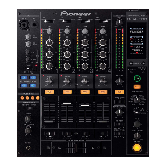
Pioneer DJM-800 Operating Instructions Manual
Owner's manual
Hide thumbs
Also See for DJM-800:
- Service manual (176 pages) ,
- Operating instructions manual (128 pages) ,
- Manual del instrucción (24 pages)
Table of Contents
Advertisement
Advertisement
Table of Contents

Related Manuals for Pioneer DJM-800


Summary of Contents for Pioneer DJM-800
-
Page 1: Operating Instructions
DJ MIXER DJM-800 Operating Instructions... - Page 2 In some countries or regions, the shape of the power plug and power outlet may sometimes differ from that shown in the explanatory drawings. However the method of connecting and operating the unit is the same.
-
Page 3: Cautions Regarding Handling
÷ When the surfaces are very dirty, wipe with a soft cloth be exposed to high temperatures or humidity. ÷ Do not install the unit in a location which is exposed to dipped in some neutral cleanser diluted five or six times direct rays of the sun, or near stoves or radiators. -
Page 4: Table Of Contents
MIDI signal format, allowing external components to be controlled via MIDI. 6 Other functions ¶ A control cable can be used to connect the unit to a Pioneer DJ CD player, thus allowing playback to be linked to operation of the fader (“fader start play”). -
Page 5: Connections
48 kHz/24-bit format. 21. Power inlet (AC IN) ÷ Turn power off before changing this switch position. Use the accessory power cord to connect to an AC power outlet of the 12. DIGITAL/CD input selector switches proper voltage. -
Page 6: Connecting Inputs
CONNECTIONS (CONNECTING INPUTS) Always turn off the power switch and disconnect the power plug from its outlet when making or changing connections. CONNECTING INPUTS Pioneer DJ CD players Connecting other line level output devices Connect a DJ CD player’s audio output connectors to one of the To use a cassette deck or other CD player, connect the component’s... -
Page 7: Connecting External Effectors, Output Connectors
L channel output. In this way, the mixed L+R audio signal will volume for this output is controlled by the BOOTH MONITOR level be sent to the effector. In the same way, use a cable with Ø6.3 mm dial, independently of the master output level setting. -
Page 8: Connecting Microphone And Headphones
Connect the power cord last. ÷ After completing all other connections, connect the accessory power cord to the AC inlet on the back of the player, then connect the plug to a standard wall outlet or to the auxiliary power outlet of your amplifier. -
Page 9: Names And Functions Of Parts
Microphone sound is output normally. 1. Microphone 1 input jack (MIC 1) TALK OVER: Use to connect a microphone with an XLR or phone plug. Microphone sound is output; when sound is input to a 2. Microphone 2 input jack (MIC 2) - Page 10 ¶ At the left setting, the curve produces a rapid signal rise. 12. Channel equalizer high-range adjust dial (HI) (As soon as the cross fader lever leaves the [A] side, the [B] Use to adjust the treble (high-range) frequency sound for each channel sound is produced.)
- Page 11 ¶ If the TIME dial is rotated while depressing the TAP button, direct BPM can be set manually. ¶ If the TIME dial is rotated while holding the TAP button and AUTO/TAP buttons depressed, the BPM can be set in 0.1 units.
-
Page 12: Display Section
(seven characters in two lines) indicates Parameter 1 display (5 digits): the name of the effect as shown below. Also, when one of the Displays parameters designated for each effect. When the beat change operations is performed as noted in the table, the... -
Page 13: Mixer Operations
1. To use a microphone, set the MIC switch to [ON] or [TALK OVER]. ¶ When the switch is set to [TALK OVER], any time a sound of MASTER over –15 dB is detected by the microphone, the output for all... -
Page 14: Fader Start Function
4. Set the CD player to the desired cue point, and engage cue point standby. ¶ If a cue point has already been set, it is not necessary to set the CD player to standby at the cue point. 5. At the instant you wish to start playback, move the cross fader lever. -
Page 15: Effect Functions
Also, by adding a 1/1 beat echo to the microphone, the microphone sound repeats in synch with the music beat. If a 1/1 beat echo is applied to the vocal portion of a track, the song takes on an effect reminiscent of a “round”. - Page 16 6. FILTER 12. ROLL In units of 1/4, 1/2, 1/1, 2/1, 4/1, 8/1, 16/1, 32/1, or 64/1 beat, the Sounds of 1/16, 1/8, 1/4, 1/2, 1/1, 2/1, 4/1, 8/1, or 16/1 beat are filter frequency is moved, greatly changing the sound recorded and output repetitively.
-
Page 17: Producing Beat Effects
“1/1” (or “4/1”, depending on the effect selected), parameter (time) for the selected effect. and the time for 1 beat (1/4 notes) or 4 beats will be set as See P. 19 for details regarding the effect on parameter 1 of rotating the effect time. -
Page 18: Type Of Sound-Color Effect
The track is filtered and output. ¶ The button for the selected effect will flash. ¶ The selected effect is applied equally to channels 1 to 4. ¶ If the flashing button is pressed, it lights steadily, and the effect 3. CRUSH turns OFF. -
Page 19: Effect Parameters
(*1) When the effect channel selector is set to [CF.A], [CF.B], or [MASTER], even if the effect monitor is turned ON, if the selected channel’s sound is not output to the master output, the effect sound will not be heard. -
Page 20: Midi Settings
¶ Synch may not be achieved if the track’s BPM cannot be =120 Audio detected and measured stably. ¶ BPM values set with the TAP mode can also be used to output =120 MIDI OUT the timing clock. 2. Press the MIDI START/STOP button. -
Page 21: Program Change
— — REV DELAY TRANS SNAPSHOT FILTER FLANGER PHASER Once the DJM-800 is setup with parameters for a given purpose, that — — — REVERB set of parameters can be recorded as a snapshot. When snapshot of — — —... -
Page 22: Troubleshooting
÷ MIDI sequencer is not supported type. ÷ MIDI sequencers that do not support MIDI timing lock cannot be synchronized. Static electricity or other external interference may cause the unit to malfunction. To restore normal operation, turn the power off and then on again. -
Page 23: Specifications
PHONO input connectors Power consumption ..............32 W RCA pin jacks .................. 3 Operating temperature ..... +5 ˚C to +35 ˚C (+41 ˚F to +95 ˚F) LINE/CD input connectors Operating humidity ....5 % to 85 % (without condensation) RCA pin jacks .................. 4 Weight ................ -
Page 24: Block Diagram
All rights reserved. PIONEER CORPORATION 1-1, Shin-ogura, Saiwai-ku, Kawasaki-shi, Kanagawa 212-0031, Japan PIONEER ELECTRONICS (USA) INC. P.O. BOX 1540, Long Beach, California 90801-1540, U.S.A. TEL: (800) 421-1404 PIONEER ELECTRONICS OF CANADA, INC. Industrial Products Department: 300 Allstate Parkway, Markham, Ontario L3R OP2, Canada...