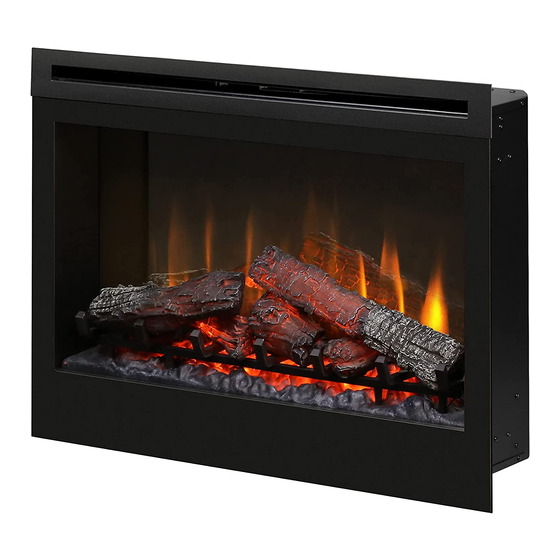
Dimplex DF3033ST Service Manual
33” wide screen fireplace with full feature remote control
Hide thumbs
Also See for DF3033ST:
- Owner's manual (23 pages) ,
- User manual (14 pages) ,
- Troubleshooting manual (2 pages)
Table of Contents
Advertisement
IMPORTANT SAFETY INFORMATION: Always read this manual first before attempting to service this
fireplace. For your safety, always comply with all warnings and safety instructions contained in this
manual to prevent personal injury or property damage.
Dimplex North America Limited
1367 Industrial Road Cambridge ON Canada N1R 7G8
1-888-346-7539 www.dimplex.com
In keeping with our policy of continuous product development, we reserve the right to make changes without notice.
© 2012 Dimplex North America Limited
Service Manual
33" Wide Screen Fireplace with
Full Feature Remote Control
Model Number
DF3033ST
DCF44GS
DFG3033
UL Part Number
6905060159 to 0359
REV
PCN
Date
00
11534
Jul 22, 09
01
11622
Sep 11, 09
02
12974
Aug 31, 11
03
13181
Feb 14, 12
04
-
Nov 20, 12
7400210000R04
Advertisement
Table of Contents

Related Manuals for Dimplex DF3033ST


Summary of Contents for Dimplex DF3033ST
- Page 1 1367 Industrial Road Cambridge ON Canada N1R 7G8 13181 Feb 14, 12 1-888-346-7539 www.dimplex.com Nov 20, 12 In keeping with our policy of continuous product development, we reserve the right to make changes without notice. © 2012 Dimplex North America Limited 7400210000R04...
-
Page 2: Table Of Contents
Table of Contents Operation ............... . 3 Maintenance . -
Page 3: Operation
The remote control can send another frequency code CAUTION: If you need to continuously reset the heater, to the remote control receiver to eliminate interference. unplug the unit and call Dimplex North America Limited at 1-888-346-7539 for technical support. Please have your ①... -
Page 4: Maintenance
Disable Heat Figure 3 - Remote Control Functions If desired, depending on the season, the heater on the unit A. Room Temperature can be disabled. The unit will operate in the same fashion, B. Set Temperature with remainder of the controls. C. -
Page 5: Glass Cleaning
Figure 4 Figure 5 Exploded view to show detail Flicker Motor Light Filter Upper Bulbs Shaft and rubber Bracket bushing Flicker Motor Media Tray or Log Set (depending on model) Screws to remove (2 per side) Lower Bulbs (3) Bulbs Flicker Rod Figure 6 Front... -
Page 6: Exploded Parts Diagram
DFG3033 - Media Tray ....0440410100RP 433MHz - Silver Dimplex Logo . . . . . . . 3000350100RP Flicker Motor . -
Page 7: Wiring Diagram
Wiring Diagram 2800070700 84141036CF On/Off Power Cord A LIVE Switch 4100040200 84141030FF JP16 NEUTRAL 4 pin Molex PIN 4 JP12 JP15 PIN 4 Heater Assembly Remote 200330200 Control Receiver (433MHz) 2500400200 3000300200 2500400100 Remote 2500150200 Control Receiver JP10 3000240400 (2.4GHz) 2500380200 3000880100 Flicker... -
Page 8: Partially Reflective Glass Replacement
Partially Reflective Glass Replacement Figure 8 WARNING: If unit was operating prior to servicing allow Top Cover at least 10 minutes for light bulbs and heating element to cool off to avoid accidental burning of skin. WARNING: Disconnect power before attempting any maintenance or cleaning to reduce the risk of electric shock or damage to persons. -
Page 9: Remote Switchboard Replacement
across the front half of the fireplace. Figure 10 Underside of Baffle and Locate the Remote Switchboard mounted on the Switch Mount Bracket underside of the Baffle panel on the right side (Figure 10) and disconnect the white wire harness that leads to the remote control receiver. -
Page 10: Remote Control Replacement
(Figure 11). Replace Flicker Rod. ! NOTE: When removing the Flicker Rod, damage may Reassemble firebox in reverse order as above and occur if bent excessively. If the Flicker Rod is damaged, replace in mantel. replace to insure proper operation. Remote Control Replacement Cautiously bend the Flicker Rod enough so that the Remote Control require no replacement procedure however,... -
Page 11: Heater Assembly Replacement
to remove. On newer receivers the antenna is built into the Assembly and panel in one hand, remove the five (5) board. heater mounting screws, noting the center screw is of a larger diameter (Figure 14). The Remote Control Receiver is fastened to the underside of the top panel by seven (7) Mounting Studs, Separate the Heater Assembly from the top panel. -
Page 12: Lower Light Replacement
enough slack of power cord from within the firebox to new light sockets, using an appropriate wire connector work with. Use caution as the power cord is connected (customer supplied). to internal components (Figure 16). Wrap all of the wires together with the protective covering Using pliers, squeeze the sides of the plastic wire clamp and secure with tie wraps. -
Page 13: Troubleshooting Guide
Troubleshooting Guide PROBLEM CAUSE SOLUTION General Circuit breaker trips or fuse blows Short in unit wiring. Trace wiring in unit. when unit is turned on Improper circuit current rating Additional appliances may exceed the current rating of the circuit breaker or fuse. Plug unit into another outlet or install unit on a dedicated 15 amp circuit. - Page 14 PROBLEM CAUSE SOLUTION Heater Heater is not turning off (Manually) Improper operation Refer to Operation Section Defective Remote Switchboard Replace Remote Switchboard Defective Remote Control Receiver Replace Remote Control Receiver. Initialize Remote Control and Remote Control Receiver. Heater is not turning on (Manually) Improper operation Refer to Operation Section Heater has been disabled...