
Related Manuals for AMX Electroluminescent LCD Touch Panels


Summary of Contents for AMX Electroluminescent LCD Touch Panels
- Page 1 instruction manual Electroluminescent LCD Touch Panels (Firmware version G3 or higher) Tou c h Pa n els an d A cc e ss o r ie s...
- Page 2 This warranty extends only to products purchased directly from AMX Corporation or an Authorized AMX Dealer. AMX Corporation is not liable for any damages caused by its products or for the failure of its products to perform. This includes any lost profits, lost savings, incidental damages, or consequential damages. AMX Corporation is not liable for any claim made by a third party or by an AMX Dealer for a third party.
-
Page 3: Table Of Contents
Using TPDesign3 to Download Bitmaps, Icons, and Fonts..........17 Creating a Bargraph and Joystick ................... 18 Adding a bargraph or joystick button\..................18 Setting Bargraph and Joystick Properties ............... 18 Setting the level code......................18 Programming ......................19 System Send_Commands....................19 Electroluminescent LCD Touch Panels... - Page 4 Button String Commands ....................36 Upgrading the Firmware ..................39 AXT-EL+ EPROM Replacement ..................39 AXM-EL+ (/PB) and AXD-EL+ (/PB) EPROM Replacement........... 40 Replacing the Batteries ..................43 AXT-EL+ Batteries ......................43 AXD-EL+ (/PB), and AXM-EL+/PB Batteries ..............44 Electroluminescent LCD Touch Panels...
-
Page 5: Product Information
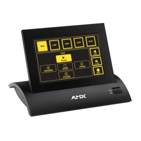
2-pin male 12 VDC power supply Enclosure: AXD-EL+ Metal sub-plate and bezel with black or white matte finish AXT-EL+ TiltScreen tabletop console; black plastic with matte finish AXM-EL+ 19" (48.3 cm) rack-mount; metal with black matte finish (4 rack units high) Electroluminescent LCD Touch Panels... - Page 6 • 12 VDC power supply, 1.9 A (110 VAC installations only) (AXT-EL+ only) • WAV-PK WavePack • SMT-PK SmartPack Options: AXD-EL+ (/PB) • External pushbuttons (AXD-EL+ (/PB)) • UniMount Back Box (BB-TP1) and sub-plate bezel security plates Electroluminescent LCD Touch Panels...
-
Page 7: Installation
5. Disconnect the AXlink connector from the Central Controller. Then, disconnect the optional RS-232 wiring from the external RS-232 device connected to the touch panel. 6. Fasten the low-profile Back Box to the surface using the #6-32 machine screws supplied with the enclosure. Electroluminescent LCD Touch Panels... -
Page 8: Installing Touch Panels And A Bb-Tp1 Back Box (Solid Surface)
4. Place the BB-TP1 into the cutout and mark the threaded insert positions as shown in FIG. 3. 5. Remove the BB-TP1 and drill holes (A and B) for the panel (FIG. 3). Then, place #6-32 threaded inserts into the four holes marked 'B' in the cutout dimensions illustration. Electroluminescent LCD Touch Panels... - Page 9 Once attached to the faceplate, the security screws cannot be replaced without removing the battery. 15. Reconnect the AXlink wiring to the Central Controller and RS-232 wiring (optional) to the external RS-232 device. The touch panel will beep when you apply power. Electroluminescent LCD Touch Panels...
-
Page 10: Installing Touch Panels And A Bb-Tp1 Back Box (Plasterboard)
1. Cut out the surface using the dimensions shown in FIG. 5. FIG. 5 Decor style (AXD) and BB-TP2 cutout dimensions for plasterboard The touch panel must always be installed with the release slot located at the bottom. Electroluminescent LCD Touch Panels... -
Page 11: Rack-Mount Panels
#6-32 screws. Then, tighten the bottom-left and top-right screws. 4. Connect the AXlink and RS-232 wiring (optional) to the touch panel. Refer to the (DB-9) RS- 232 Connector Pinouts table on page 10 for pinout descriptions. The touch panel beeps on power-up. Electroluminescent LCD Touch Panels... -
Page 12: Wiring The Touch Panel
The maximum wiring lengths for using AXlink power are based on a minimum of 13.5 volts available at the Central Controller's power supply. Refer to the Specifications section on page 1 for more information on power requirements. Electroluminescent LCD Touch Panels... -
Page 13: Using Axlink For Data And Power
Wiring Guidelines for 1.5 A table on page 9. Connect only the GND wire on the AXlink connector when using a 12 VDC power supply. Do not connect the PWR wire to the AXlink connector's PWR (+) terminal. Electroluminescent LCD Touch Panels... -
Page 14: Using The (Db-9) Rs-232 Connector For Mouse Control Or Data
Optional 7 to 8-pin connector 5 (GND) 5 (GND) 3 (TXD) 3 (TXD) 2 (RXD) 2 (RXD) Touch panel Mouse or PC, DB-9 connector DB-9 connector Male Female FIG. 10 DB-9 RS-232 connector and power supply wiring diagram Electroluminescent LCD Touch Panels... -
Page 15: Designing Touch Panel Pages
The keypad button opens a keypad so you can enter a password or value assignment. All keypad buttons are interactive except for the entry display. Decision buttons Decision buttons appear when an operation has two options and requires verification before an action is performed. Electroluminescent LCD Touch Panels... -
Page 16: Activating Edit Mode
2. Press PROTECTED SETUP to open the keypad. 3. Enter 1988 (default password) in the keypad and press ENTER to open Protected Setup page. If you press ENTER after typing an incorrect password, you are immediately returned to the previous page. Electroluminescent LCD Touch Panels... - Page 17 7. Press to open the Edit bar. The options, in the Edit bar (FIG. 14), are EDIT BUTTON PAGE used to design and modify button and page settings. Edit bar FIG. 14 Main page with Edit bar Electroluminescent LCD Touch Panels...
-
Page 18: Setting The Device Base
Resizing a button 1. Press BUTTON on the Edit bar to open the BUTTON menu. 2. Press RESIZE. Then, touch any edge of the button and drag. Removing your finger from the panel saves the button dimensions. Electroluminescent LCD Touch Panels... -
Page 19: Defining On-Screen And External Button Properties
4. Press CHAN to open the keypad and enter a channel value of 1 - 255. The source code uses the channel code number to identify the button and its programmed operations. The channel code for non-active buttons is 0. Electroluminescent LCD Touch Panels... -
Page 20: Setting The Variable Text Code
4. Press the TEXT button to open the palette. Select a color to use for the text. 5. Press EXIT SAVE CHANGE in the Button Properties page to save the new button properties and return to the current page. Electroluminescent LCD Touch Panels... -
Page 21: Adding Text, Icons, And Bitmaps To A Button
8. After clicking Connect, the Available Panels list appears in the Available Panels field. Click Begin to start downloading the project file into the panel. 9. After completing the download, the bitmaps, icons and fonts that were downloaded are now accessible via the BITMAPS, ICONS and FONTS menus. Electroluminescent LCD Touch Panels... -
Page 22: Creating A Bargraph And Joystick
5. Enter a number 1 – 8. Each device can have from 1 – 8 levels except joysticks, where the range is 1 – 7. 6. Press ENTER to save, close the keypad, and return to the Button Properties page. Electroluminescent LCD Touch Panels... -
Page 23: Programming
Example: SEND_COMMAND TP,"’AKEYP-1988’" Opens the touch panel keypad with 1988 in the display. AKEYR Syntax: Closes/opens the "’AKEYR’" touch panel key- Example: board/pad. SEND_COMMAND TP,"’AKEYR’" Closes the keyboard/keypad opened using the ’AKEYB’, ’AKEYP’, or ’PKEYP’ commands. Electroluminescent LCD Touch Panels... - Page 24 Flips the touch panel to the page named MAIN PAGE. PKEYP Syntax: Displays aster- "’PKEYP-<number string>’" isks (*) for keypad Variables: entries. number string = 0 - 9999 Example: SEND_COMMAND TP, "’PKEYP-1988’" Displays the touch panel keypad with **** instead of 1988. Electroluminescent LCD Touch Panels...
- Page 25 = 1 - 255 ASCII characters Example: SEND_COMMAND TP, "’$ST 31’" The number entered is based on the minute increments available within the touch panel such as 30, 60, 120 minutes. This number will be rounded down to match an increment. Electroluminescent LCD Touch Panels...
- Page 26 TPAGEON Syntax: Activates page "’TPAGEON’" tracking. Example: SEND_COMMAND TP,’TPAGEON’ DEFINE_DEVICE TP1 = 128 (*AMX Touch Panel*) TP2 = 129 (*AMX Touch Panel*) DEFINE_VARIABLE TP1_BUFFER[100] (*Buffer for TP1*) TP2_BUFFER[100] (*Buffer for TP2*) TRASH[50] (*For Parsing Above*) DEFINE_START CREATE_BUFFER TP1,TP1_BUFFER CREATE_BUFFER TP2,TP2_BUFFER...
-
Page 27: Programming Numbers
Refer to the Setting the variable text code section on page 16 for more information on variable fonts. Font Styles and Programming Numbers Font styles Font styles Extra small Extra large Small Hollow medium Medium Hollow extra large Large 32 - 255 Variable fonts Electroluminescent LCD Touch Panels... -
Page 28: Shorthand Send_Commands
= 1 - 255 color number = See the Colors and Programming Numbers table on page 23. Example: SEND_COMMAND TP,"’@CBN’,2,87" Sets the ON feedback border color to Black for variable text button 2. Electroluminescent LCD Touch Panels... - Page 29 = 1 – 255 color number = See the Colors and Programming Numbers table on page 23. Example: SEND_COMMAND TP,"’@CTF’,1,17" Sets the OFF feedback text color to Yellow for variable text button 1. Electroluminescent LCD Touch Panels...
- Page 30 = target popup page name page name = target touch panel page name Example: SEND_COMMAND TP,"’PPF-Laser Disc 2 Transport Control; Laser Disc Control Page’" Deactivates the Laser Disc 2 Transport Control popup page on the Laser Disc Control Page. Electroluminescent LCD Touch Panels...
- Page 31 Sets the page flip password to 1988. @SSL Syntax: Changes the "’@SSL-<string>’" Sleep string sent Variables: to the Controller string = alphanumeric characters when the touch panel activates Example: sleep mode. SEND_COMMAND TP,"’@SSL-Touch Panel Deactivated’" Sends Touch Panel Deactivated to the Controller. Electroluminescent LCD Touch Panels...
-
Page 32: Color Send_Commands
Sets variable text button 1 to: FILL COLOR ON = Yellow FILL COLOR OFF = Black BORDER COLOR ON = Yellow BORDER COLOR OFF = Black TEXT COLOR ON = Black TEXT COLOR OFF = Yellow Electroluminescent LCD Touch Panels... - Page 33 = See the Colors and Programming Numbers table on page 23. color. page name = 1 - 50 ASCII characters (Page names are case sensitive.) Example: SEND_COMMAND TP,"’CPAGE255-MAIN PAGE’" Sets the background color on the MAIN PAGE to Transparent. Electroluminescent LCD Touch Panels...
-
Page 34: Variable Text Send_Commands
Sets the state for button 255 to Off. BTON Syntax: Sets a specific "’BTON’,<variable text address>’" button's active Variables: state to On. variable text address = 1 - 255 Example: SEND_COMMAND TP,"’BTON’,128" Sets the state for button 128 to On. Electroluminescent LCD Touch Panels... - Page 35 = 1 - 255 border style = See the Border Styles and Programming Numbers table on page 24. Example: SEND_COMMAND TP,"’ICON,25-6’" Changes the variable text button 25 border style to double-rounded. Electroluminescent LCD Touch Panels...
- Page 36 = 1 - 255 button text = Enter button text to appear on button Example: SEND_COMMAND TP,"’TEXT2-VCR|PLAY’" Sets the VCR and PLAY text on variable button 2. The | character places VCR above PLAY on the button. Electroluminescent LCD Touch Panels...
-
Page 37: Shorthand Variable Text Commands
Adds a bitmap file to a button. Syntax: "’@BMP’,<variable text address>,’<bitmap>’" Variables: variable text address = 1 - 255 bitmap = Bitmap Example: SEND_COMMAND TP,"’@BMP’,85,’Bitmap1’" Adds the Bitmap1 file to button 85. Electroluminescent LCD Touch Panels... - Page 38 Sets the text on button 56 to variable font style 32. @ICO Syntax: Assigns an icon to "’@ICO’,<variable text address>,<icon>" a button. Variables: variable text address = 1 - 255 icon file number = 1 - 255 Example: SEND_COMMAND TP,"’@ICO’,16,12" Adds icon 12 on button 16. Electroluminescent LCD Touch Panels...
- Page 39 Characters for Middle-Eastern languages such as Arabic are not supported within the Unicode fonts because they are bi-directional. Buttons with Unicode fonts can only be created and edited using TPDesign3 and NetLinx Studio; Refer to the respective manuals for additional information. Electroluminescent LCD Touch Panels...
-
Page 40: Button String Commands
Sends the Calibrate command to another panel through the Serial Port. $SP "$SC 1,"’@TXT’,1,’TEST’"" Uses the $SP command to send a Send Command ($SC ***) to another panel through the Serial Port. Electroluminescent LCD Touch Panels... - Page 41 "’$TO <touch output enabling via the program port>’" coordinates out Variables: through the pro- touch output enabling = 0 (Input Touch Only), 1 (Input and Output Touch) gram port. Example: $TO 0 Sets the panel only to input touch. Electroluminescent LCD Touch Panels...
- Page 42 Programming Electroluminescent LCD Touch Panels...
-
Page 43: Upgrading The Firmware
Upgrading the Firmware Upgrading the Firmware In order to upgrade the firmware in the panel, you can either return the panel to AMX or replace the necessary EPROM chips yourself. Standard memory on the G3 boards for the EL+ series of touch panels is 256 KB of base memory. -
Page 44: Axm-El+ (/Pb) And Axd-El+ (/Pb) Eprom Replacement
7. Gently pry the EPROMs from their connection base until they begin to loosen. Carefully pull them out by either using an EPROM removal device or by gently pulling them from their base (making sure to evenly pull the prongs from their socket holes). Electroluminescent LCD Touch Panels... - Page 45 12. Replace the housing on the touch panel and align the screw holes. Insert the seven Phillips- head screws and tighten. 13. Plug all connectors back into the touch panel. 14. Re-install the unit to its appropriate mounting surface. Electroluminescent LCD Touch Panels...
- Page 46 Upgrading the Firmware Electroluminescent LCD Touch Panels...
-
Page 47: Replacing The Batteries
212 °F (100 °C). Never solder directly to the battery or expose the contents of the battery to water. 7. Rotate the circuit card back to the original position and place it in the touch panel housing. Do not insert the mounting screw. Electroluminescent LCD Touch Panels... -
Page 48: Axd-El+ (/Pb), And Axm-El+/Pb Batteries
9. Return the touch panel to the Back Box or equipment rack and reconnect all the connectors. 10. Insert the four rack mounting screws and tighten. 11. Place the Decor-style faceplate onto the bezel and install the engraved overlay. Electroluminescent LCD Touch Panels... - Page 49 Replacing the Batteries Electroluminescent LCD Touch Panels...
- Page 50 AMX reserves the right to alter specifications without notice at any time. brussels • dallas • los angeles • mexico city • philadelphia • shanghai • singapore • tampa • toronto* • york 3000 research drive, richardson, TX 75082 USA • 469.624.8000 • 800.222.0193 • fax 469.624.7153 • technical support 800.932.6993...